Q6DCTX714802.11b/g WLAN miniPCI Card
Creatix Polymedia GmbH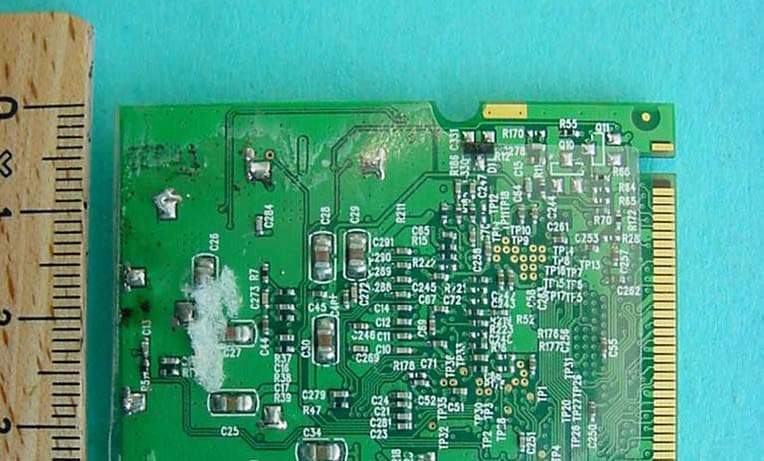
Click to zoom
Application Details
- Equipment Class
- DTS - Digital Transmission System
- Date of Grant
- Dec 11, 2003
- Application Purpose
- Original Equipment
- Date of Application
- Dec 11, 2003
- Equipment Note
- 802.11b/g WLAN miniPCI Card
- Frequency Range
- 2412.00000000 - 2462.00000000
- Company
- Creatix Polymedia GmbH
- Country
- Germany
Documents & Files
Document Text
Text extracted from the exhibit documents filed with the FCC. Open a document above to read the original.
Users Manual
Creatix WLAN Modem Combo CTX714 V.2 User Manual This handbook is protected by copyright. It must not be copied, reproduced, translated or transmitted in electronic media, in whole or in part. Accuracy of the information is not guaranteed. Any mention in this handbook of products of other manufacturers is for information purposes only and represents no misuse of trademarks. Safety instructions for Data-Fax-Modem This equipment has been designed and tested in accordance with the requirements of Standard IEC 950 „Safety of Information Technology Equipment, Including Electrical Business Equipment“ Extracts from these requirements according Standard IEC 950: x The FAX-Modem was evaluated for use in maximum ambient temperature of 40 °C. x The FAX-Modem may only be used in countries where the modem is certified. x Neither the data transmission cable nor the telephone cable should be connected or disconnected during a thunderstorm. mv205a0.402uk Regulatory Statements FCC Certification The United States Federal Communication Commission and the Canadian Department of Communication have established certain rules governing the use of electronic equipment. Part15, Class B This device complies with Part 15 of the FCC Rules. Operation is subject to the following two conditions: (1) This device my not cause harmful interference, and (2) this device must accept any interference received, including interference that may cause undesired operation. This equipment has been tested and found to comply with the limits for a Class B digital device, pursuant to Part 15 of the FCC Rules. These limits are designed to provide reasonable protection against harmful interference in a residential installation. This equipment generates, uses and can radiate radio frequency energy and, if not installed and used in accordance with the instructions, may cause harmful interference to radio communications. However, there is no guarantee that interference will not occur in a particular installation. If this equipment does cause harmful interference to radio or on, the user is encouraged to try to correct the interference by one or more of the following measures: - Reorient or relocate the receiving antenna. - Increase the separation between the equipment and receiver. - Connect the equipment into an outlet on a circuit different from that to which the receiver is connected. - Consult the dealer or an experienced radio/TV technician for help. Caution: 1. This equipment complies with FCC radiation exposure limits set forth for an uncontrolled environment. This equipment should be installed and operated with minimum distance 20cm between the radiator and your body. 2. This transmitter must not be co-located or operating in conjunction with any other antenna or transmitter. 3. Changes or modifications made to this equipment not expressly approved byCreatix Polymedia GmbH may void the FCC authorization to operate this equipment Table of Contents Chapter 0 INSTALLATION WLAN Chapter 1 INTRODUCTION ................................ 1-1 What is a Modem? ...................................................................................... 1-1 About this Modem ....................................................................................... 1-1 The 56K Technology.................................................................................... 1-2 General Description .................................................................................... 1-2 Auto-Answering............................................................................................ 1-3 Installation Instructions Windows 95/98 .............................................. 1-3 Windows 9x and ME ...................................... 1-3 Windows NT 4.0 ............................................ 1-4 Windows 2000/XP ......................................... 1-4 Factory Settings .......................................................................................... 1-4 Chapter 2 AT COMMANDS: DATA MODEM ...... 2-1 Guidelines for Using AT Commands .......................................................... 2-1 AT - Attention Code .................................................................................... 2-3 The ESC Sequence .................................................................................... .2-3 A - Answer Mode ......................................................................................... 2-4 A/ - Repeat Last Command Line ................................................................ 2-4 B - BELL/CCITT .......................................................................................... 2-4 D - Automatic Dialing and Dialing Parameters ........................................... .2-5 E – Echo Function ...................................................................................... 2-6 H – Switch Hook Check (Replace Handset) – Go "On Hook" .................... 2-6 I – Firmware Information .............................................................................. 2-6 L – Volume Level ........................................................................................ .2-6 M – Switching the Loudspeaker On and ..................................................... 2-6 N – Recognizing Type of Modulation........................................................... 2-7 O – Return to online Operation.................................................................... 2-7 Q – Modem Messages On / Off .................................................................. 2-7 S – Reading and Modifying Registers ........................................................ 2-7 V – Verbal or Numeric Modem Messages .................................................. 2-7 W – Controlling Connect Messages ........................................................... 2-8 X – Result Code Type/Call Progress .......................................................... 2-9 Y – Long Space Disconnect ........................................…
Text truncated - open the document above for the full version.
External Photos
CETECOM ICT Services GmbH Test report no.:4-1137-01-03/03Issue date:2003-10-30Page 65 (68) Photographs of the equipment CETECOM ICT Services GmbH Test report no.:4-1137-01-03/03Issue date:2003-10-30Page 66 (68) Photographs
ID Label/Location Info
CTX 714_V2 USA SAP: 40005326 Ratings: +3,3V 350mA FCC ID: Q6DCTX714 US:CPGM507BCTX714
Internal Photos
CETECOM ICT Services GmbH Test report no.:4-1137-01-03/03Issue date:2003-10-30Page 67 (68) Photographs
Test Report
CETECOM ICT Services GmbH Radio Satellite Communication Untertürkheimer Straße 6-10 . D-66117 SaarbrückenTelefon: +49 (0)681 598-0Telefax: -9075 RSC14issue test report consist of68 PagesPage 1 (68) Recognized by the Federal Communications Commission Anechoic chamber registration no: 90462 (FCC) Anechoic chamber registration no: 3436 (IC) TCB ID: DE 0001 Accredited by the German Accreditation Council DAR–Registration Number TTI–P–G 166/98 Independent ETSI compliance test house ETSI Accredited Bluetooth™ Test Facility (BQTF) Test Report No.: 4-1137-01-03/03 FCC Part 15.247 / CANADA RSS-210 CTX 714 V.2 FCC ID: Q6DCTX714 CETECOM – ICT Services GmbH Untertürkheimerstr. 6-10 66117 Saarbrücken, Germany Telephone: + 49 (0) 681 / 598-0 Fax: + 49 (0) 681 / 598-9075 CETECOM ICT Services GmbH Test report nr.:4-1137-01-03/031Issue date: 2003-10-30Page 2 (68) Table of Contents 1 General information 1.1 Notes 1.2 Testing laboratory 1.3 Details of applicant 1.4 Application details 1.5 Test item 1.6 Test standards 2 Technical test 2.1 Summary of test results 2.2 Test report 1 General information 1.1 Notes The test results of this test report relate exclusively to the test item specified in 1.5. The CETECOM ICT Services GmbH does not assume responsibility for any conclusions and generalisations drawn from the test results with regard to other specimens or samples of the type of the equipment represented by the test item. The test report may only be reproduced or published in full. Reproduction or publication of extracts from the report requires the prior written approval of the CETECOM ICT Services GmbH. 1.2Testing laboratory CETECOM ICT Services GmbH Untertürkheimer Straße 6 - 10 66117 Saarbrücken Germany Telefone: + 49 681 598 - 9100 Telefax : + 49 681 598 - 9075 E-mail: [email protected] Internet: www.cetecom.de Accredited testing laboratory DAR-registration number : TTI-P-G-166/98-30 Accredited Bluetooth TM Test Facility (BQTF) BLUETOOTH TM is a trademark owned by Bluetooth SIG, Inc. and licensed to CETECOM CETECOM ICT Services GmbH Test report no.:4-1137-01-03/03Issue date:2003-10-30Page 3 (68) 1.3Details of applicant Name :Creatix Polymedia Gesellschaft für Kommunikationssysteme GmbH Street :Heinrich-Barth-Str. 3 City :66115 Saarbrücken Country :Germany Telephone:+49 (0) 681 98 11-3 00 Telefax :+49 (0) 681 98 11-3 90 Contact :Herr Frank von Ehren Telephone:+49 (0) 681 98 11-4 13 1.4Application details Date of receipt of application : 2003-10-06 Date of receipt of test item : 2003-10-06 Date of test : 2003-10-21 to 2003-10-24 1.5Test item Type of equipment : 2.4 GHz WLAN MiniPCI card 802.11b/g Type designation: CTX 714 V.2 Manufacturer: -applicant - Street: City: Country: Serial number: FCC ID: Q6DCTX714 Hardware:V.2 Software :V.2 Additional information : Frequency:2412 – 2462 MHz Type of modulation:22M0P7D (DSSS) / (OFDM) Ch. Sep. : 5 MHz Number of channels :11 Antenna:Dedicated antenna connected via Coax Adapter Power supply:3.3 V via MiniPCI PC slot Output power cond./rad.:DSSS System: 209.89 mW / 113.76 mW EIRP OFDM System: 381.94 mW / 209.41 mW EIRP Type of equipment:Class B Temperature range :0°C - +40°C Field strength peak:103.1 dBμV/m Occupied bandwidth:DSSS: 11632 kHz OFDM: 16432 kHz Temperature range:0°C - +40°C 1.6Test standards: FCC Part 15 §15.247 / CANADA RSS-210 CETECOM ICT Services GmbH Test report no.:4-1137-01-03/03Issue date:2003-10-30Page 4 (68) Test set-ups: We measured at 11 Mbit/s (DSSS) and 54 Mbit/s (OFDM) where necessary. The tests were performed with a special shielded PC with extender card to get free radiation of the test sample. We also used special test software to set the samples in the required modes. We also made a conducted measurement with a Laptop to show the reaction of the sample on the AC line. 2 Technical test 2.1 Summary of test results The radiated measurements are performed in vertical and horizontal plane in the frequency range from 9 kHz to 25 GHz in semi-anechoic chambers. The EUT is positioned on a non- conductive support with a height of 0.80 m above a conductive ground plane that covers the whole chamber. The receiving antennas are conform with specifications ANSI C63.2-1996 clause 15 and ANSI C63.4-2001 clause 4.1.5. These antennas can be moved over the height range between 1.0 m and 4.0 m in order to search for maximum field strength emitted from EUT. The measurement distances between EUT and receiving antennas are indicated in the test setups for the various frequency ranges. For each measurement, the EUT is rotated in all three axes until the maximum field strength is received. The wanted and unwanted emissions are received by spectrum analyzers where the detector modes and resolution bandwidths over various frequency ranges are set according to requirement ANSI C63-4-2001 clause 4.2. CETECOM ICT Services GmbH Test report no.:4-1137-01-03/03Issue date:2003-10-30Page 5 (68) Antennas are conform with ANSI C63.2-1996 item 15. 9 kHz - 30 MHz: Quasi Peak measurement, 9kHz Bandwidth, loop antenna. 30 MHz - 200 MHz: Quasi Peak measurement, 120KHz Bandwidth, biconical antenna 200MHz - 1GHz: Quasi Peak measurement, 120KHz Bandwidth, log periodic antenna >1GHz: Average, RBW 1MHz, VBW 10 Hz, wave-guide horn All measurement settings are according to FCC 15.35, 15.205, 15.209, 15.247 and the „Measurement guidelines for DTS systems“. No deviations from the technical specification(s) were ascertained in the course of the tests performed. The product fulfills also the requirements for CANADA RSS-210. FINAL VERDICT : PASS Technical responsibility for area of testing : 2003-12-03RSC 8414 Ames H. DateSectionNameSignature Technical responsibility for area of testing : 2003-12-03RSC8412Hausknecht D. DateSectionNameSignature CETECOM ICT Services GmbH Test report no.:4-1137-01-03/03Issue date:2003-10-30Page 6 (68) 2.2Test report TEST REPORT Test report no. : 4-1137-01-03/03 CETECOM ICT Services GmbH Test report no.:4-1137-01-03/03Issue date:2003-10-30Page 7 (68)…
Text truncated - open the document above for the full version.
Test Setup Photos
CETECOM ICT Services GmbH Test report no.:4-1137-01-03/03Issue date:2003-10-30Page 63 (68) Test site RADIATED EMISSIONS CETECOM ICT Services GmbH Test report no.:4-1137-01-03/03Issue date:2003-10-30Page 64 (68) Test site CONDUCTED EMISSIONS
Contact Information
Applicant
Frank von Ehren(Product Manager)
[email protected]+49 681 9811 413
Test Firm
Cetecom ICT Services GmbHRalf Hoehn
Technical Specifications
| # | Rule Parts | Frequency Range | Power Output |
|---|---|---|---|
| 1 | 15C | 2.41 GHz - 2.46 GHz | 382.00 mW |
Other Applications from Creatix Polymedia GmbH
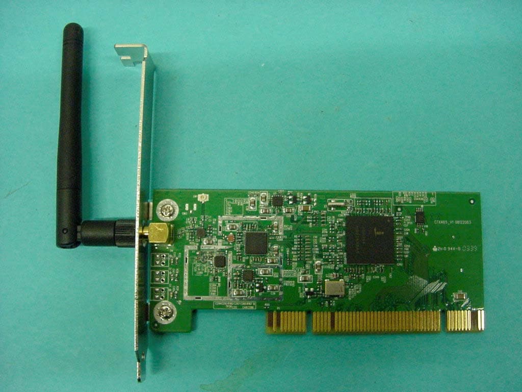
Q6DCTX405
Sep 19, 2004WLAN PCI Card 802.11 b/g
Equipment Class
DTS - Digital Transmission SystemQ6DCTX712V2
Sep 11, 2003802.11b WLAN miniPCI Card
Equipment Class
DTS - Digital Transmission System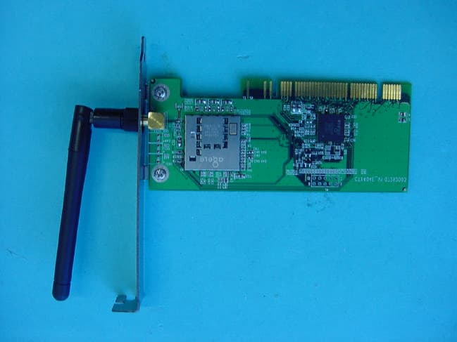
Q6DCTX404EV2
Sep 03, 2003IEEE 802.11B WLAN PCI Card
Equipment Class
DTS - Digital Transmission System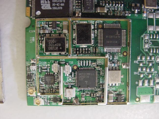
Q6DCTX712AV2
Jun 25, 2003802.11b WLAN miniPCI Card
Equipment Class
DTS - Digital Transmission System