Q6K1000-7251ATM SECURITY SYSTEM
3Si Security Systems Inc.
Click to zoom
Application Details
- Equipment Class
- DSC - Part 15 Security/Remote Control Transmitter
- Date of Grant
- Aug 31, 2004
- Application Purpose
- Original Equipment
- Date of Application
- Aug 31, 2004
- Equipment Note
- ATM SECURITY SYSTEM
- Frequency Range
- 433.92000000 - 433.92000000
- Company
- 3Si Security Systems Inc.
- Country
- United States
Documents & Files
Document Text
Text extracted from the exhibit documents filed with the FCC. Open a document above to read the original.
Users Manual
5015 B.U. Bowman Drive Buford, GA 30518 USA Voice: 770-831-8048 Fax: 770-831-8598 Certification Test Report 433.92 MHz Alarm System FCC ID: Q6K 1000-7251 FCC Rule Part: 15.231 ACS Report Number: 04-0056-15C231 Manufacturer: 3SI Security Systems Model: MCU Installation and Operators Guide 486 Thomas Jones Way (800) 523-1430 (V) Exton, PA 19341(610)-280-2079 (F) Overview: The Octopus ATM Defense System is a wireless system consisting of an ATM Monitor and Control Unit (MCU) and Cassette Staining Units (CSU). This system, once installed into an ATM, becomes a closed wireless protection network within the ATM. The operational frequency of the system is set to allow worldwide operation and deployment of the protection system. Currently, the system is UL, FCC, IC, and CE compliant. The system is designed for continuous monitoring and protection of ATM cassette based currency for two years. Both the MCU and CSU are powered via custom battery packs which allow installation without requiring interface to external power. The mechanical dimensions of the product allow the MCU to be placed almost anywhere within the ATM safe, while the bracket design of the CSU allows for fast field installation. Actual Stained Currency --- Deny the Prize Features: • Self-contained battery operated system with life cycle greater than 2 years. • Continuous wireless communications status monitoring. • Fast installation time, usually less than 1 hour • Provides protection against tilt, motion, power failures and breach of the ATM safe. • Compatible with most leading ATM sensor array packages. • Requires single wire interface to begin protection • Uses industry preferred currency staining method. • Proprietary wireless communications protocol. • Can provides external remote monitoring signals. Octopus ATM Defense System Installation and Operation Guide Page 2 of 25 Table of Contents Overview: ...................................................................................................................................................................1 Features: .....................................................................................................................................................................1 Table of Contents........................................................................................................................................................2 Product Specification:.................................................................................................................................................6 Components Overview: ..............................................................................................................................................8 Cassette Staining Unit (CSU) .....................................................................................................................................8 Monitor and Control Unit (MCU) ..............................................................................................................................9 Installation Instructions: ...........................................................................................................................................10 CSU Installation ..................................................................................................................................................10 MCU Installation .................................................................................................................................................11 Basic Operation: .......................................................................................................................................................13 Detailed Operation:...................................................................................................................................................15 Appendix A: System Indication and Error Code Readout Appendix B: Optional Components Appendix C: MCU Sensor Array and RIM Wiring Appendix D: Configuration Jumper Selection Guide Appendix E: Installation Instruction Diebold MMD Cassette Appendix F: Installation Instruction DeLaRue MDDM Cassette Appendix G: Installation Instruction Perto "A" C-130 Cassette Appendix H: Installation Instruction DeLaRue NMD Cassette Appendix I: Installation Instruction NCR Cassette Appendix J:Mode Jumper Selection (Preliminary Only) Appendix T:Test Mode Octopus ATM Defense System Installation and Operation Guide Page 3 of 25 Copyright 3SI Security Systems, Inc. 2003 All Rights Reserved. Except as allowed by copyright laws or herein, reproduction, adaptation, or translation without prior written permission is prohibited. A user of the Octopus ATM Defense System associated with this guide is granted a license to print hard copies of this guide for internal or company use subject to the restriction not to sell, resell, or otherwise distribute the hard copies. Warranty The information contained in this document is subject to change without notice. 3SI Security Systems makes no warranty of any kind with respect to this information. 3SI SECURITY SYSTEMS SPECIFICALLY DISCLAIMS THE IMPLIED WARRANTY OF MERCHANTABILITY AND FITNESS FOR A PARTICULAR PURPOSE. Octopus ATM Defense System Installation and Operation Guide Page 4 of 25 FCC regulations NOTE: This equipment has been tested and found to comply with the limits for a Class B digital device, pursuant to Part 15 of the FCC Rules. These limits are designed to provide reasonable protection against harmful interference in a residential installation. This equipment generates, uses and can radiate radio frequency energy and, if not installed and used in accordance with the instructions, may cause harmful interference to radio communications. However, there is no guarantee that interference will not occur in a particular installation. If this equipment does cause harmful interference to radio or television reception, which can be determi…
Text truncated - open the document above for the full version.
Block Diagram
5015 B.U. Bowman Drive Buford, GA 30518 USA Voice: 770-831-8048 Fax: 770-831-8598 Certification Test Report 433.92 MHz Alarm System FCC ID: Q6K 1000-7251 FCC Rule Part: 15.231 ACS Report Number: 04-0056-15C231 Manufacturer: 3SI Security Systems Model: MCU Block Diagram Smoke Generat or Driver Circuit Cent ral Alarm Cl o s u r e Cir c u i t uProc Volt Reg Fu s e Vreg EEPROM Re s e t Clock1 Clock2 ATM SW Closure Circuit Tilt Sw Ho rz Tilt Sw Vert RF Xc v r M o d u l e Buzzer MCU PCB Mo t io n Sensor Do or SW Cl o s u r e Cir c u i t Manual Act ivat ion Closure Circuit Sp ar e Closure Circuit Wire Mesh SW Closure Circuit Sp ar e Closure Circuit Activation Closure Circuit Act ivat ion Cl o s u r e Cir c u i t SA W
Block Diagram
5015 B.U. Bowman Drive Buford, GA 30518 USA Voice: 770-831-8048 Fax: 770-831-8598 Certification Test Report 433.92 MHz Alarm System FCC ID: Q6K 1000-7251 FCC Rule Part: 15.231 ACS Report Number: 04-0056-15C231 Manufacturer: 3SI Security Systems Model: MCU Block Diagram Smoke Generat or Driver Circuit Cent ral Alarm Cl o s u r e Cir c u i t uProc Volt Reg Fu s e Vreg EEPROM Re s e t Clock1 Clock2 ATM SW Closure Circuit Tilt Sw Ho rz Tilt Sw Vert RF Xc v r M o d u l e Buzzer MCU PCB Mo t io n Sensor Do or SW Cl o s u r e Cir c u i t Manual Act ivat ion Closure Circuit Sp ar e Closure Circuit Wire Mesh SW Closure Circuit Sp ar e Closure Circuit Activation Closure Circuit Act ivat ion Cl o s u r e Cir c u i t SA W Transceiver Block Diagram Figure 1 is the schematic of the transceiver, U7. Please refer to Figure 1 for the following discussions. Figure #1 The main voltage to the RF circuitry is filtered by C27, L7, & C20 in a “pi” configuration. C22 & C35 provide RF bypassing on the transceiver control lines.
Cover Letter(s)
486 Thomas Jones Way Exton, PA 19341 (610)-280-2005 (main) (800)-523-1430 (610)-280-2077 (fax) CONFIDENTIALITY REQUEST Federal Communications Commission Date: September 1, 2004 Equipment Authorization Branch 7435 Oakland Mills Road Columbia, MD 21046 Gentlemen: 3Si Security Systems respectfully requests confidentiality of certain materials provided with the submission of the Octopus ATM Security System under FCC ID: Q6K 1000-7251 in accordance with FCC Regulations 0.459. The confidentiality request applies to the Bill of Material & Schematics contained in this filing. The MCU Octopus ATM Security System has been developed at considerable effort and expense by 3Si Security Systems. These items are considered as Trade Secrets and therefore public access to the proprietary material could possible result in duplication of equipment that could severely damage the company's business advantage. I appreciate your assistance in this matter. Sincerely, Name: Mitchell L.Ingle Title: Sr. Development Engineer
External Photos
5015 B.U. Bowman Drive Buford, GA 30518 USA Voice: 770-831-8048 Fax: 770-831-8598 Certification Test Report 433.92 MHz Alarm System FCC ID: Q6K 1000-7251 FCC Rule Part: 15.231 ACS Report Number: 04-0056-15C231 Manufacturer: 3SI Security Systems Model: Octopus ATM Security System (MCU) External Photographs 5015 B.U. Bowman Drive Buford, GA 30518 USA Voice: 770-831-8048 Fax: 770-831-8598 Figure 1: Top/Rear Angled View 5015 B.U. Bowman Drive Buford, GA 30518 USA Voice: 770-831-8048 Fax: 770-831-8598 Figure 2: Top/Front Angled View 5015 B.U. Bowman Drive Buford, GA 30518 USA Voice: 770-831-8048 Fax: 770-831-8598 Figure 3: Bottom/Rear Angled View 5015 B.U. Bowman Drive Buford, GA 30518 USA Voice: 770-831-8048 Fax: 770-831-8598 Figure 4: Bottom/Front Angled View
ID Label/Location Info
5015 B.U. Bowman Drive Buford, GA 30518 USA Voice: 770-831-8048 Fax: 770-831-8598 Certification Test Report 433.92 MHz Alarm System FCC ID: Q6K 1000-7251 FCC Rule Part: 15.231 ACS Report Number: 04-0056-15C231 Manufacturer: 3SI Security Systems Model: MCU Label Information 5015 B.U. Bowman Drive Buford, GA 30518 USA Voice: 770-831-8048 Fax: 770-831-8598
Internal Photos
5015 B.U. Bowman Drive Buford, GA 30518 USA Voice: 770-831-8048 Fax: 770-831-8598 Certification Test Report 433.92 MHz Alarm System FCC ID: Q6K 1000-7251 FCC Rule Part: 15.231 ACS Report Number: 04-0056-15C231 Manufacturer: 3SI Security Systems Model: Octopus ATM Security System (MCU) Internal Photographs 5015 B.U. Bowman Drive Buford, GA 30518 USA Voice: 770-831-8048 Fax: 770-831-8598 Figure 1: Test Setup - Top/Front Angle 5015 B.U. Bowman Drive Buford, GA 30518 USA Voice: 770-831-8048 Fax: 770-831-8598 Figure 2: Test Setup – Top/Rear Angle 5015 B.U. Bowman Drive Buford, GA 30518 USA Voice: 770-831-8048 Fax: 770-831-8598 Figure 3: Test Setup - Overhead 5015 B.U. Bowman Drive Buford, GA 30518 USA Voice: 770-831-8048 Fax: 770-831-8598 Figure 4: Circuit Board – Top View 5015 B.U. Bowman Drive Buford, GA 30518 USA Voice: 770-831-8048 Fax: 770-831-8598 Figure 5: Circuit Board – Bottom View 5015 B.U. Bowman Drive Buford, GA 30518 USA Voice: 770-831-8048 Fax: 770-831-8598 Figure 6: RF Circuitry
Operational Description
5015 B.U. Bowman Drive Buford, GA 30518 USA Voice: 770-831-8048 Fax: 770-831-8598 Certification Test Report 433.92 MHz Alarm System FCC ID: Q6K 1000-7251 FCC Rule Part: 15.231 ACS Report Number: 04-0056-15C231 Manufacturer: 3SI Security Systems Model: MCU Theory of Operation Model: 1000-7251 Advanced Compliance Solutions FCC ID: Q6K 1000-7251 5015 B.U. Bowman Drive Buford, GA 30518 USA Voice: 770-831-8048 Fax: 770-831-8598 Transceiver Block Diagram Figure 1 is the schematic of the transceiver, U7. Please refer to Figure 1 for the following discussions. Figure #1 The main voltage to the RF circuitry is filtered by C27, L7, & C20 in a “pi” configuration. C22 & C35 provide RF bypassing on the transceiver control lines. Antenna Port Antennas presenting an impedance in the range of 35 to 72 ohms resistive can be satisfactorily matched to the RFIO pin with a series/shunt matching circuit. A DC path from RFIO to ground is required for ESD protection. This is accomplished by L4 & L5 on the schematic. The antenna is L6 that is resonant matched to 50 Ohms with C23 & C24. Transmitter Chain The transmitter chain consists of a SAW delay line oscillator followed by a modulated buffer amplifier. OOK modulation is chosen by setting CNTRL0 =1 and CNTRL1=0. The transmitter output turns completely off between “1” data pulses. The transmitter RF output power is proportional to the input current to the TXMOD pin. A series attenuation circuit (R30, R31, & R37) is used to adjust the peak transmitter output power. Power out is nominally set for 0.1 mW. C29 is used as a RF bypass and minimize the TX data edges. Receiver Chain The receive operation is chosen by setting CNTRL0 =1 and CNTRL1=1. A receive filter provides a three- pole, 0.05 degree equiripple low pass response with excellent group delay flatness and minimal pulse ringing. The 3 dB bandwidth of the filter is set by R36 and is optimized for a 19.2kBaud data rate. The detected signal, BBOUT is coupled to the CMPIN pin, by C26. Data Slicers The CMPIN pin drives two data slicers, which convert the analog signal from BBOUT back into a digital stream. Data slicer DS1 is a capacitively coupled comparator with the comparator’s slicing level set with resistors R34 & R35 Output Buffer The output of the transceiver was designed to drive a 500kOhms//10pF load. This was sufficiently high enough that a source-follower buffer, Q3, R45, R47, & R48 had to be incorporated to interface with the uProc. Model: 1000-7251 Advanced Compliance Solutions FCC ID: Q6K 1000-7251 5015 B.U. Bowman Drive Buford, GA 30518 USA Voice: 770-831-8048 Fax: 770-831-8598 AGC Control The purpose of the AGC function is to extend the dynamic range of the receiver, so that two transceivers can operate close together. The AGC operation is presently defeated in this circuitry, by having the AGCCAP pin tied to Vrf. If require, C21 can be quickly modified to accomplish the AGC function. Receiver Pulse Generator and RF Amplifier Bias The receiver amplifier-sequence operation is controlled by the PRATE and PWIDTH input pins. The PWIDTH pin sets the width of the ON pulse with a resistor R39 to ground. The PRATE pin sets the falling edge of one ON pulse to the rising edge of the next ON pulse with a resistor R39 to ground. RF Sleep Mode The transceiver is put into a sleep mode by setting CNTRL0 =0 and CNTRL1=0. This lowers the current drain to 0.75 uA.
Test Report
5015 B.U. Bowman Drive Buford, GA 30518 USA Voice: 770-831-8048 Fax: 770-831-8598 Certification Test Report 433.92 MHz Alarm System FCC ID: Q6K 1000-7251 FCC Rule Part: 15.231 ACS Report Number: 04-0056-15C231 Manufacturer: 3SI Security Systems Model: MCU Data Plots A Model: MCU Advanced Compliance Solutions FCC ID: Q6K 1000-7251 ACS Report: 04-0056-15C231 Advanced Compliance Solutions Page 2 Data Plots ACS Report Number: 04-0056-15C231 Manufacturer: 3SI Security Systems Model: MCU Test: Peak Power Model: MCU Advanced Compliance Solutions FCC ID: Q6K 1000-7251 ACS Report: 04-0056-15C231 Advanced Compliance Solutions Page 3 Data Plots ACS Report Number: 04-0056-15C231 Manufacturer: 3SI Security Systems Model: MCU Test: Bandwidth Limitation Model: MCU Advanced Compliance Solutions FCC ID: Q6K 1000-7251 ACS Report: 04-0056-15C231 Advanced Compliance Solutions Page 4 Data Plots ACS Report Number: 04-0056-15C231 Manufacturer: 3SI Security Systems Model: MCU Test: Spurious Emissions
Test Report
5015 B.U. Bowman Drive Buford, GA 30518 USA Voice: 770-831-8048 Fax: 770-831-8598 FCC Part 15 Certification Test Report 433.92 MHz Alarm System FCC ID: Q6K 1000-7251 FCC Rule Part: 15.231 ACS Report Number: 04-0056-15B Manufacturer: 3SI Security Systems Model: Octopus ATM Security System (MCU) Test Begin Date: March 18, 2004 Test End Date: March 18, 2004 Report Issue Date: April 30, 2004 Prepared by: Reviewed by: Richard Bianco EMI/EMC Approvals Engineer ACS, Inc. R. Sam Wismer Engineering Manager ACS, Inc. This test report shall not be reproduced except in full. This report may be reproduced in part with prior written consent of ACS, Inc. The results contained in this report are representative of the sample(s) submitted for evaluation. This report contains 10 pages Table of Contents 1.0 General 3 1.1 Introduction 3 1.2 Product Description 3 1.2.1 Intended Use 3 1.2.2 Technical Specifications 3 2.0 Location of Test Facility 3 2.1 Description of Test Facility 3 2.1.2 Open Area Test Site 4 2.1.2 Conducted Emissions Test Site 4 3.0 Applicable Standards and References 5 4.0 List of Test Equipment 6 5.0 EUT Setup Block Diagram 7 6.0 Summary of Tests 7 6.1 Section 15.207 - Power Line Conducted Emissions 7 6.1.1 Test Methodology 7 6.1.2 Test Results 7 6.2 Section 15.209 - Radiated Emissions (Unintentional Radiation) 7 6.2.1 Test Methodology 7 6.2.2 Test Results 8 6.3 Sections 15.231(a) – Transmission Duration 9 6.3.1 Test Requirement 9 6.3.2 Test Methodology 9 6.3.3 Test Results 9 6.4 Section 15.231(b) – Field Strength of Emissions 9 6.4.1 Test Requirement 10 6.4.1 Test Methodology 10 6.4.2 Test Results 10 6.5 Section 15.231(c) – Bandwidth Limitation 10 6.5.1 Test Requirement 10 6.5.1 Test Methodology 10 6.5.2 Test Results 10 7.0 CONCLUSION 10 Additional Exhibits Included In Filing Internal Photographs External Photographs Test Setup Photographs Product Labeling RF Exposure – MPE Calculations Technical Documentation Installation/Users Guide Theory of Operation System Block Diagram Parts List Data Plots Model: MCU FCC ID: Q6K 1000-7251 ACS Report: 04-0056-15C231 Advanced Compliance Solutions Page 3 1.0 GENERAL 1.1 Introduction The purpose of this report is to demonstrate compliance with 15.231 of the FCC’s Code of Federal Regulations. 1.2 Product Description The Octopus ATM Security System master control unit or MCU consist of a printed wiring board house in a protective enclosure and is located in the ATM safe area. The unit contains several sensor devices such as tilt and motion. It also monitors external contact closures from several sources for specific events and if necessary command the CSU to activate the ink staining system. The MCU is battery operated with a design target of two years of battery life. 1.2.1 Intended Use The 3Si 1000-7251 Master Cassette Unit is intended to be installed into ATM machines for theft prevention. To be installed only by trained professionals. 2.0 LOCATION OF TEST FACILTY All testing was performed by qualified ACS personnel located at the following address: ACS, Inc. 5015 B.U. Bowman Drive Buford, GA 30518 2.1 DESCRIPTION OF TEST FACILITY Both the Open Area Test Site(OATS) and Conducted Emissions site have been fully described, submitted to, and accepted by the FCC, Industry Canada and the Japanese Voluntary Control Council for Interference by information technology equipment. The following certification numbers have been issued in recognition of these accreditations and certifications: FCC Registration Number: 89450 Industry Canada Lab Code: IC 4175 VCCI Member Number: 1831 VCCI OATS Registration Number R-1526 VCCI Conducted Emissions Site Registration Number: C-1608 2.1.1 Open Area Test Site The open area test site consists of a 40’ x 66’ concrete pad covered with a perforated electro-plated galvanized sheet metal. The perforations in the sheet metal are 1/8” holes that are staggered every 3/16”. The individual sheets are placed to overlap each other by 1/4” and are riveted together to provide a continuous seam. Rivets are spaced every 3” in a 3 x 20 meter perimeter around the antenna mast and EUT area. Rivets in the remaining area are spaced as necessary to properly secure the ground plane and maintain the electrical continuity. The entire ground plane extends 12’ beyond the turntable edge and 16’ beyond the antenna mast when set to a 10 meter measurement distance. The ground plane is grounded via 4 - 8’ copper ground rods, each installed at a corner of the ground plane and bound to the ground plane using 3/4" stainless steel braided cable. The turntable is an all aluminum 10’ flush mounted table installed in an all aluminum frame. The table is remotely operated from inside the control room located 40’ from the range. The turntable is electrically bonded to the surrounding ground plane via steel fingers installed on the edge of the turn table. The steel fingers make constant contact with the ground plane during operation. Model: MCU FCC ID: Q6K 1000-7251 ACS Report: 04-0056-15C231 Advanced Compliance Solutions Page 4 Adjacent to the turntable is a 7’ x 7’ square and 4’ deep concrete pit used for support equipment if necessary. The pit is equipped with 5 - 4” PVC chases from the pit to the control room that allow for cabling to the EUT if necessary. The underside of the turntable can be accessed from the pit so cables can be supplied to the EUT from the pit. The pit is covered with 2 sheets of 1/4" diamond style re-enforced steel sheets. The sheets are painted to match the perforated steel ground plane, however the underside edges have been masked off to maintain the electrical continuity of the ground plane. All reflecting objects are located outside of the ellipse defined in ANSI C63.4. A diagram of the Open Area Test Site is shown in Figure 2.1-1 below: Figure 2.1-1: Open Area Test Site 2.1.2 Conducted Emissions Test Site Description The AC mains conducted EMI site is a shielded room with the following dimensions: ¾ Height: 3.0 Meters ¾ Width: 3.6 Me…
Text truncated - open the document above for the full version.
Test Setup Photos
5015 B.U. Bowman Drive Buford, GA 30518 USA Voice: 770-831-8048 Fax: 770-831-8598 Certification Test Report 433.92 MHz Alarm System FCC ID: Q6K 1000-7251 FCC Rule Part: 15.231 ACS Report Number: 04-0056-15C231 Manufacturer: 3SI Security Systems Model: Octopus ATM Security System (MCU) Test Setup Photographs 5015 B.U. Bowman Drive Buford, GA 30518 USA Voice: 770-831-8048 Fax: 770-831-8598 Figure 1: Unintentional Radiated Emissions – Front View 5015 B.U. Bowman Drive Buford, GA 30518 USA Voice: 770-831-8048 Fax: 770-831-8598 Figure 2: Unintentional Radiated Emissions – Rear View 5015 B.U. Bowman Drive Buford, GA 30518 USA Voice: 770-831-8048 Fax: 770-831-8598 Figure 3: Spurious Emissions – Front View 5015 B.U. Bowman Drive Buford, GA 30518 USA Voice: 770-831-8048 Fax: 770-831-8598 Figure 4: Spurious Emissions – Rear View
Contact Information
Applicant
Brandon Cromer(Systems and Technical Manager)
Test Firm
Advanced Compliance Solutions, Inc.Douglas Massey
Technical Specifications
| # | Rule Parts | Frequency Range | Power Output |
|---|---|---|---|
| 1 | 15.231 | 433.92 MHz - 433.92 MHz | - |
Other Applications from 3Si Security Systems Inc.
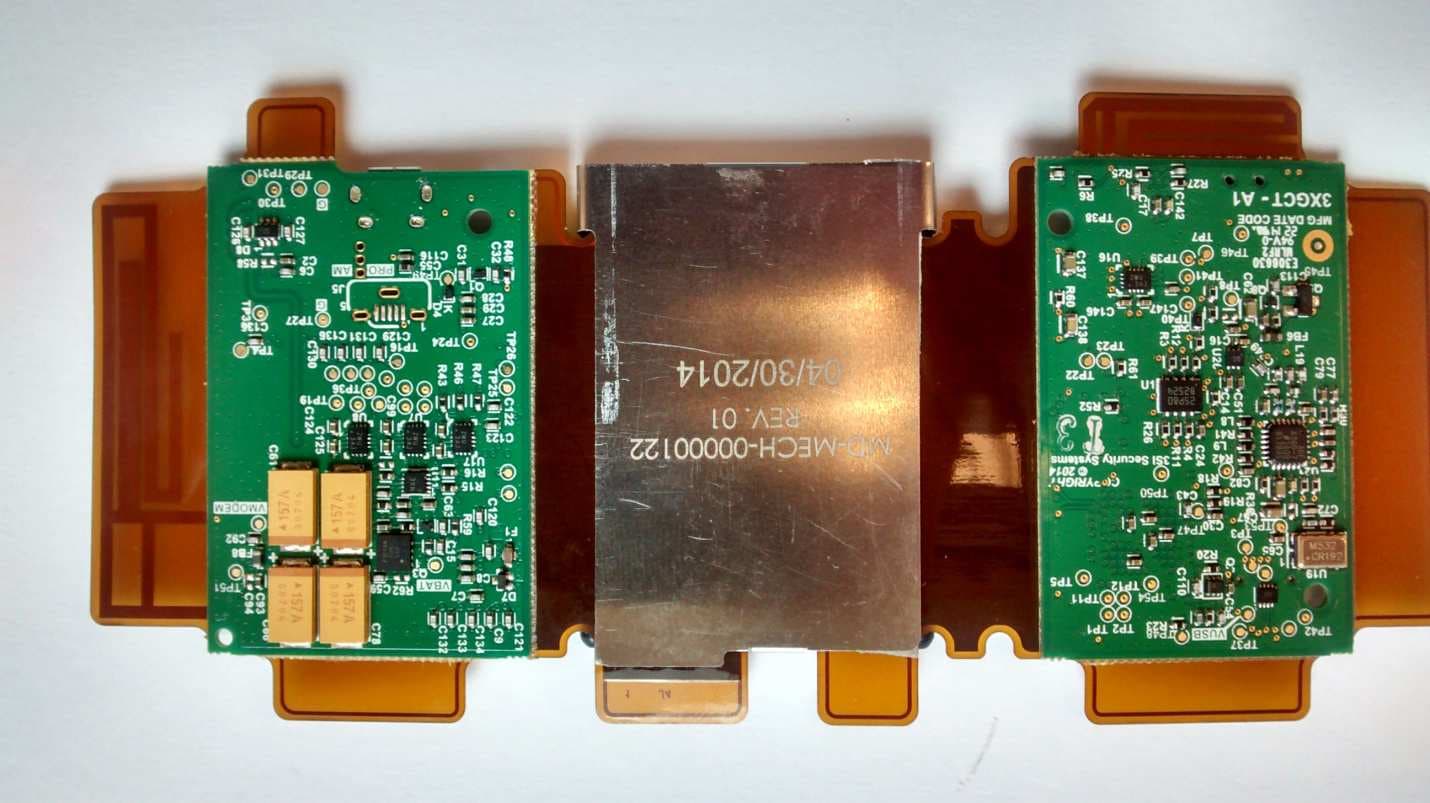
Q6KAT150119A
Jun 07, 2015Asset Tracking and Alert Device
Equipment Class
TNB - Licensed Non-Broadcast Station Transmitter
Q6KAT140720A
Jan 27, 2015Asset Tracking and Alert Device
Equipment Class
PCB - PCS Licensed Transmitter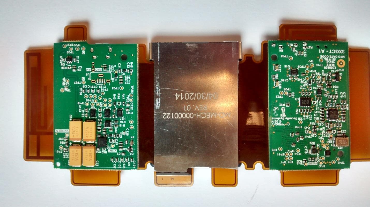
Q6KAT140901A
Dec 18, 2014Asset Tracking and Alert Device
Equipment Class
PCB - PCS Licensed Transmitter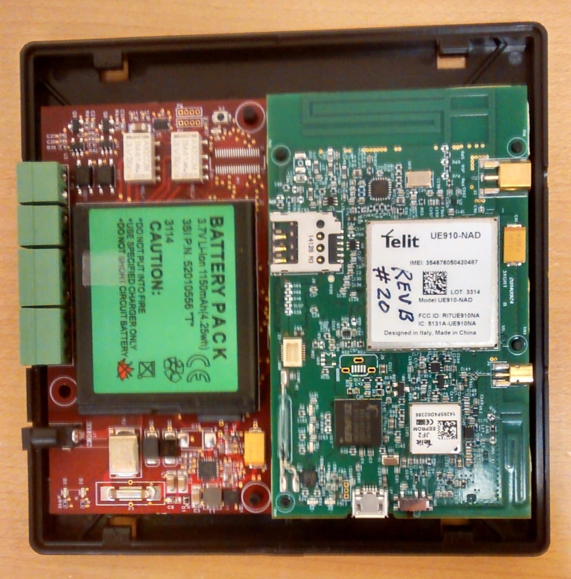
Q6KAT140704A
Dec 07, 2014Asset Tracking and Alert Device
Equipment Class
PCB - PCS Licensed Transmitter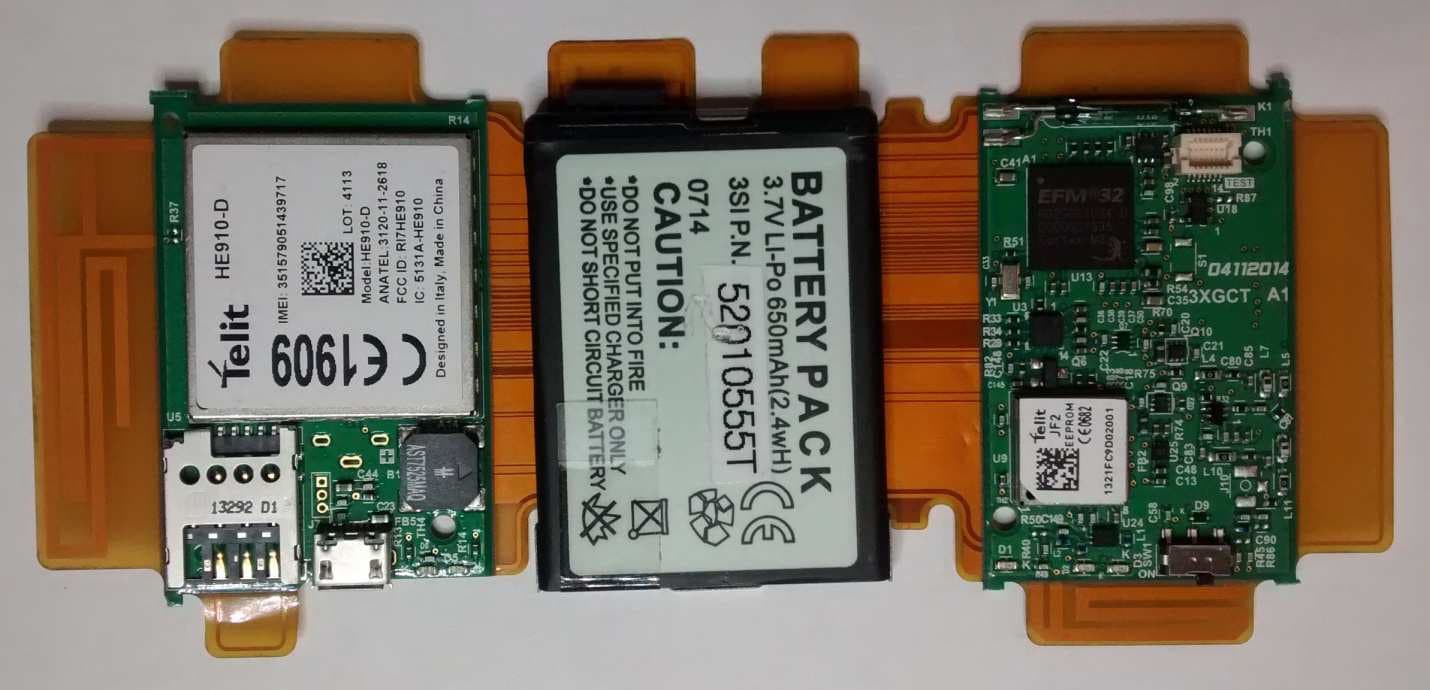
Q6KAT140317A
Jul 10, 2014Asset Tracking and Alert Device
Equipment Class
PCB - PCS Licensed Transmitter