Q6MIT450000Wireless Modem
ICP DAS Co., Ltd.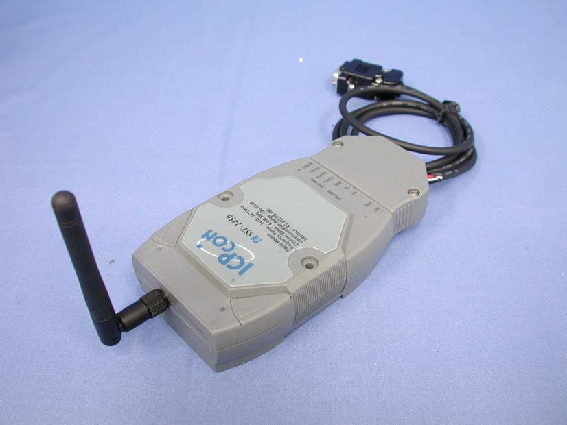
Click to zoom
Application Details
- Equipment Class
- DTS - Digital Transmission System
- Date of Grant
- Jun 02, 2003
- Application Purpose
- Original Equipment
- Date of Application
- Jun 02, 2003
- Equipment Note
- Wireless Modem
- Frequency Range
- 2410.49600000 - 2471.93600000
- Company
- ICP DAS Co., Ltd.
- Country
- Taiwan
Documents & Files
Document Text
Text extracted from the exhibit documents filed with the FCC. Open a document above to read the original.
Users Manual
SST-2450 Wireless Modem User’s Manual Ver1.5, Feb /2003, OMH-030-10, ---1 SST-2450 Wireless Modem User’s Manual Warranty All products manufactured by ICP DAS are warranted against defective materials for a period of one year from the date of delivery to the original purchaser. Warning ICP DAS assumes no liability for damages consequent to the use of this product. ICP DAS reserves the right to change this manual at any time without notice. The information furnished by ICP DAS is believed to be accurate and reliable. However, no responsibility is assumed by ICP DAS for its use, or for any infringements of patents or other rights of third parties resulting from its use. Copyright Copyright 2002 by ICP DAS. All rights are reserved. Trademark The names used for identification only may be registered trademarks of their respective companies. SST-2450 Wireless Modem User’s Manual Ver1.5, Feb /2003, OMH-030-10, ---2 Table of Contents 1. Introduction...........................................................................................................3 2. Specifications........................................................................................................4 3. Product Description...............................................................................................5 3.1. Pin assignment........................................................................................5 3.2. Block diagram..........................................................................................6 4. Applications..........................................................................................................7 4.1. Peer to Peer............................................................................................7 4.1.1. PC to PC connections -- Using Mode 1.......................................8 4.1.2. Connecting a PC to the 7000 module – Using Mode 2.................9 4.1.3. 7188 Embedded Controller to 7000 module – Using Mode 3......10 4.1.4. Connecting a PC to a PLC – Using Mode 3................................11 4.1.5. Using the 7188 as a Bridge -- Using Mode 3..............................12 4.2. Network communication.........................................................................13 4.2.1. Application 1...........................................................................13 4.2.2. Application 2...........................................................................14 5. Quick Start instructions for the SST-2450...............................................................15 5.1. Installing the software............................................................................15 5.2. SST-2450 Setting..................................................................................17 5.3. Testing the SST-2450.............................................................................19 6. Troubleshooting................................................................................................... 20 7. Dimensions.........................................................................................................21 8. Din-rail Mounting................................................................................................. 22 9. Appendix............................................................................................................. 23 SST-2450 Wireless Modem User’s Manual Ver1.5, Feb /2003, OMH-030-10, ---3 1. Introduction SST-2450EXT is a spread spectrum radio modem with controlling an RS-232/RS-485 interface port. It is designed for data acquisition and control applications between a host and remote sensors. It is also useful for those applications where the installation of cable wire is inconvenient. The SST-2450 can be used not only in peer-to-peer mode (refer to page 8), but also in a multi-point structure (refer to page 13). The SST-2450 is based on a direct sequence spread spectrum and RF technology, operating In the ISM bands with a Frequency Range of 2410.496MHz~2471.936MHz. The Channel Spacing is 4.096MHz. The SST-2450 is similar to the SST-2400, with the major difference being the setting control method. The SST-2400 is set using jumpers, whereas the SST-2450 is set using a software utility. The older SST-2400 can work in conjunction with the new SST-2450 by changing its internal 8051 chip. The new chip includes updated firmware, so please contact us and we will send a new chip. Refer to page 26 for detail. SST-2450 Wireless Modem User’s Manual Ver1.5, Feb /2003, OMH-030-10, ---5 3. Product Description 3.1. Pin assignment Radio Modem Frequency Range : 2410~2471MHz Channel Space : 4,096 Mhz Communication Range : 100-300M Interface :RS-232/RS-485 SST-2450 SETGNDRX TX GND(Y)DATA+(G)DATA-(R)+Vs(B)GND (RS-232)(RS-485) 1 10 20 11 SST-2450 Wireless Modem User’s Manual Ver1.5, Feb /2003, OMH-030-10, ---6 3.2. Block diagram The SST-2450 wave signal cannot pass through metallic obstacles. So this product is not suitable for this type of metallic environment. The signal can pass thorough a cement wall, but will be weakened to half its efficiency for every 15cm of the wall’s thickness. Transceiver SST-2450 Wireless Modem User’s Manual Ver1.5, Feb /2003, OMH-030-10, ---7 4. Applications 4.1. Peer to Peer There are three types of peer to peer operational modes to choose from. The following table outlines the settings information and limitations. Mode Description: 1 In this mode, the SST-2450 can accept and transmit any signal from the device. This mode works by using a sample and rebuild. The SST module samples the input signal then converts it into a wave signal technique before transmitting it to another SST module. When the other SST module receives the wave signal, it transforms the signal back into the original format. The sample rate used is 32kb per second, so the device can’t accept higher speed signals. The maximum signal speed is less than 9600 bps. Any data format may be need in this mode. Setting Limitative: Bau…
Text truncated - open the document above for the full version.
Block Diagram
sst2450 (1) (943x632x24b jpeg)
External Photos
Report No.: 02AH054FI Page : 1 of 8 Version:1.0 Attachment 2 : EUT Detailed Photographs (1) EUT Photo (2) EUT Photo
ID Label/Location Info
公司:303新竹縣湖口鄉新竹工業區光復北路111號 No. 111, Kuang-Fu N. Rd., Hsin-Chu Industrial Park, HuKou Shiang, HSINCHU 303, Taiwan. Tel:886-3-597-3366 Fax:886-3-597-3733 Http:www.icpdas.com E-mail:[email protected] FCC ID.: Q6MIT450000 FCC ID AND DoC Label The FCC ID and DoC Label will be placed on the equipment as shown in the photograph below. Wireless Modem ICP CON Model No.: SST-2450 TESTED TO COMPLY WITH FCC STANDARDS FOR HOME OR OFFICE USE S/N: Made in Taiwan Wireless Modem Model No.: SST-2450 F F C C C C I I D D : : Q6MIT450000 This device complies with Part 15 of the FCC Rules. Operation is subject to the following two conditions: (1) this device may not cause harmful interference and (2) this device must accept any interference received, including interference that may cause undesired operation. S/N: Made in Taiwan
ID Label/Location Info
公司:303新竹縣湖口鄉新竹工業區光復北路111號 No. 111, Kuang-Fu N. Rd., Hsin-Chu Industrial Park, HuKou Shiang, HSINCHU 303, Taiwan. Tel:886-3-597-3366 Fax:886-3-597-3733 Http:www.icpdas.com E-mail:[email protected] FCC ID.: Q6MIT450000 FCC ID AND DoC Label The FCC ID and DoC Label will be placed on the equipment as shown in the photograph below. Wireless Modem ICP CON Model No.: SST-2450 TESTED TO COMPLY WITH FCC STANDARDS FOR HOME OR OFFICE USE S/N: Made in Taiwan Wireless Modem Model No.: SST-2450 F F C C C C I I D D : : Q6MIT450000 This device complies with Part 15 of the FCC Rules. Operation is subject to the following two conditions: (1) this device may not cause harmful interference and (2) this device must accept any interference received, including interference that may cause undesired operation. S/N: Made in Taiwan
Internal Photos
Report No.: 02AH054FI Page : 2 of 8 Version:1.0 (3) EUT Photo (4) EUT Photo Report No.: 02AH054FI Page : 3 of 8 Version:1.0 (5) EUT Photo (6) EUT Photo Report No.: 02AH054FI Page : 4 of 8 Version:1.0 (7) EUT Photo (8) EUT Photo Report No.: 02AH054FI Page : 5 of 8 Version:1.0 (9) EUT Photo (10) EUT Photo Report No.: 02AH054FI Page : 6 of 8 Version:1.0 (11) EUT Photo (12) EUT Photo Report No.: 02AH054FI Page : 7 of 8 Version:1.0 (13) EUT Photo (14) EUT Photo Report No.: 02AH054FI Page : 8 of 8 Version:1.0 (15) EUT Photo (16) EUT Photo
Operational Description
Report No. 02AH054FI Page: 6 of 37 Version:1.0 1.2. Operational Description EUT is a Wireless Modem with 16 channels. The device adapts Direct Sequence spread spectrum modulation. The connector antenna was provides diversity function to improve the receiving function. This Wireless Modem is an IEEE 802.11b Wireless LAN adapter. It allows your computer to connect to a wireless network and to share resources, such as files or printers without being bound to the network wires. Operation in 2.4GHz Direct Sequence Spectrum radio transmission, the Wireless Modem transfers data at speeds up to 64/128-bit Wired Equivalent Protection (WEP) algorithm is used. In addition, its standard compliance ensures that it can communicate with any 802.11b network.
Schematics
rf模組電 (1553x1089x24b jpeg) sst2450 (1515x893x24b jpeg) sst2450- (1523x963x24b jpeg)
Test Report
Report No. 02AH054FI Page: 1 of 37 Version:1.0 Test Report Product Name: Wireless Modem Model No.: SST-2450 FCC ID.: Q6MIT450000 Applicant : ICP DAS CO., LTD Address : NO.111,Kuangfu N.Rd., Hukou Shiang , Hsinchu, Taiwan, R.O.C. Date of Receipt : Oct. 18, 2002 Date of Test : Apr 22, 2003 Report No. : 02AH054FI The test results relate only to the samples tested. The test report shall not be reproduced except in full without the written approval of QuieTek Corporation. This report must not be used to claim product endorsement by NVLAP any agency of the U.S. Government Report No. 02AH054FI Page: 2 of 37 Version:1.0 Test Report Certification Test Date : Apr 22, 2003 Report No. : 02AH054FI The Test Results relate only to the samples tested. The test report shall not be reproduced except in full without the written approval of QuieTek Corporation. This report must not be used to claim product endorsement by NVLAP any agency of the U.S. Government Product Name : Wireless Modem Applicant : ICP DAS CO., LTD Address : NO.111,Kuangfu N.Rd., Hukou Shiang , Hsinchu, Taiwan, R.O.C. Manufacturer : ICP DAS CO., LTD Model No. : SST-2450 FCC ID. : Q6MIT450000 Rated Voltage : DC 10~30V Trade Name : ICP CON Measurement Standard : FCC Part 15 Subpart C Paragraph 15.247 Measurement Procedure : ANSI C63.4: 1992 Test Result : Complied Documented By : ( Ellie Cheng ) Tested By : ( Kenny Jwo ) Approved By : ( Kevin Wang ) Accredited by NIST (NVLAP) NVLAP Lab Code: 200347-0 Report No. 02AH054FI Page: 3 of 37 Version:1.0 TABLE OF CONTENTS Description Page 1. GENERAL INFORMATION .....................................................................................................5 1.1. EUT Description............................................................................................................................5 1.2. Operational Description ................................................................................................................6 1.3. Tested System Datails....................................................................................................................7 1.4. Configuration of tested System .....................................................................................................8 1.5. EUT Exercise Software .................................................................................................................8 1.6. Test Facility ...................................................................................................................................9 2. Conducted Emission..................................................................................................................10 2.1. Test Equipment............................................................................................................................10 2.2. Test Setup ....................................................................................................................................10 2.3. Limits ..........................................................................................................................................10 2.4. Test Procedure .............................................................................................................................11 2.5. Test Result of Conducted Emission.............................................................................................12 3. Peak Power Output ...................................................................................................................13 3.1. Test Equipment............................................................................................................................13 3.2. Test Setup ....................................................................................................................................13 3.3. Limits ..........................................................................................................................................13 3.4. Test Result of Peak Power Output...............................................................................................14 4. RF Exposure Evaluation ...........................................................................................................15 4.1. Limits ..........................................................................................................................................15 4.2. Test Procedure .............................................................................................................................15 4.3. Test Result of RF Exposure Evaluation.......................................................................................16 5. Radiated Emission .....................................................................................................................17 5.1. Test Equipment............................................................................................................................17 5.2. Test Setup ....................................................................................................................................17 5.3. Limits ..........................................................................................................................................18 5.4. Test Procedure .............................................................................................................................19 5.5. Test Result of Radiated Emission................................................................................................20 6. Band Edge ..................................................................................................................................26 6.1. Test Equipment............................................................................................................................26 6.2. Test Setup ............................................................................................................…
Text truncated - open the document above for the full version.
Test Setup Photos
Report No.: 02AH054FI Page : 1 of 2 Version:1.0 Attachment 1: EUT Test Setup Photographs Front View of Radiated Test Back View of Radiated Test Report No.: 02AH054FI Page : 2 of 2 Version:1.0 Front View of Radiated Test (Horn)
Contact Information
Applicant
King Fu(Engineer)
Test Firm
DEKRA Testing and Certification Co., Ltd.Sky Hsu
Technical Specifications
| # | Rule Parts | Frequency Range | Power Output |
|---|---|---|---|
| 1 | 15C | 2.41 GHz - 2.47 GHz | 129.00 mW |
Other Applications from ICP DAS Co., Ltd.
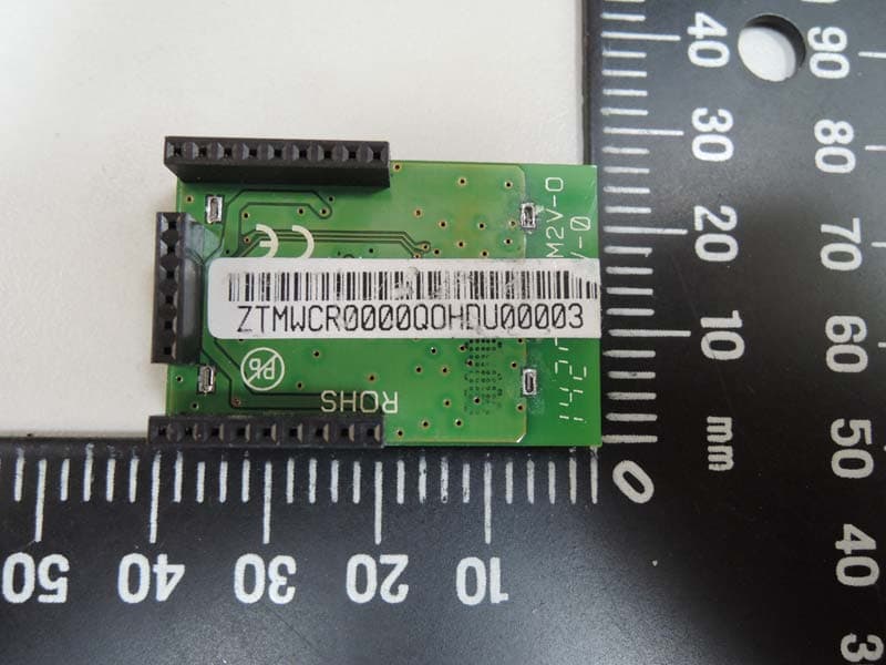
Q6M-ZTM-WP
Jul 15, 2015RF Modem
Equipment Class
DTS - Digital Transmission System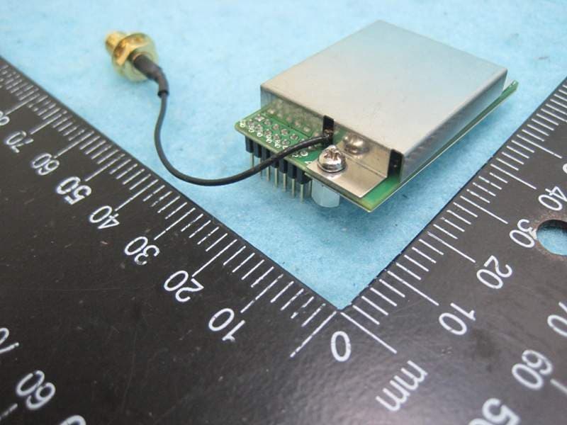
Q6M-ZM31001100-PA
Mar 17, 2013Wireless Module
Equipment Class
DTS - Digital Transmission System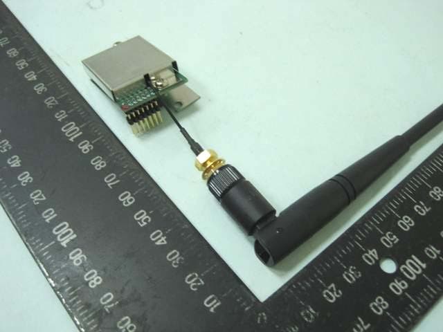
Q6MZBUPS0001
May 16, 2010ZigBee Module
Equipment Class
DTS - Digital Transmission System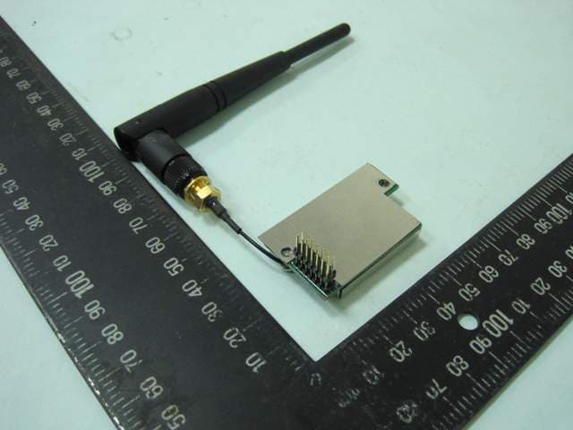
Q6MZBUPH0001
May 16, 2010ZigBee Module
Equipment Class
DTS - Digital Transmission System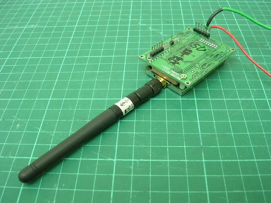
Q6M3SDSST-24M
Mar 31, 2005Wireless Modem Module
Equipment Class
DTS - Digital Transmission System