Q87-AM10Cisco AM10 USB Network Adapter
LINKSYS LLC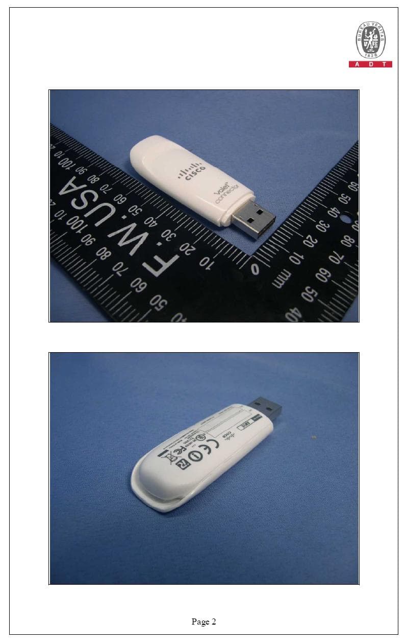
Click to zoom
Application Details
- Equipment Class
- DTS - Digital Transmission System
- Date of Grant
- Feb 09, 2010
- Application Purpose
- Original Equipment
- Date of Application
- Feb 09, 2010
- Equipment Note
- Cisco AM10 USB Network Adapter
- Frequency Range
- 2412.00000000 - 2462.00000000
- Company
- LINKSYS LLC
- Country
- United States
Documents & Files
Document Text
Text extracted from the exhibit documents filed with the FCC. Open a document above to read the original.
Users Manual
user guide user guide iii Contents Chapter 1: Product Overview 1 Storing the Cap . . . . . . . . . . . . . . . . . . . . . . . . . . . . . . . . . . . . . . . . . . . . . . . 1 Chapter 2: Wireless Network Configuration 2 Windows 7 Wireless Configuration. . . . . . . . . . . . . . . . . . . . . . . . . . . . . . . . . . . 2 Windows Vista Configuration . . . . . . . . . . . . . . . . . . . . . . . . . . . . . . . . . . . . . . 3 Windows XP Wireless Zero Configuration . . . . . . . . . . . . . . . . . . . . . . . . . . . . . . 5 Appendix A: Troubleshooting 6 Appendix B: Specifications 7 Appendix C: Warranty Information 8 Limited Warranty . . . . . . . . . . . . . . . . . . . . . . . . . . . . . . . . . . . . . . . . . . . . . . 8 Appendix D: Regulatory Information 10 FCC Statement . . . . . . . . . . . . . . . . . . . . . . . . . . . . . . . . . . . . . . . . . . . . . . .10 FCC Radiation Exposure Statement . . . . . . . . . . . . . . . . . . . . . . . . . . . . . . . . . .10 Safety Notices . . . . . . . . . . . . . . . . . . . . . . . . . . . . . . . . . . . . . . . . . . . . . . . .10 Industry Canada Statement . . . . . . . . . . . . . . . . . . . . . . . . . . . . . . . . . . . . . . .11 Règlement d’Industry Canada . . . . . . . . . . . . . . . . . . . . . . . . . . . . . . . . . . . . .11 Wireless Disclaimer . . . . . . . . . . . . . . . . . . . . . . . . . . . . . . . . . . . . . . . . . . . .11 Avis de non-responsabilité concernant les appareils sans fil . . . . . . . . . . . . . . . . . .11 User Information for Consumer Products Covered by EU Directive 2002/96/EC on Waste Electric and Electronic Equipment (WEEE) . . . . . . . . . . . . . . . . . . . . . . . . . . . . . .12 Appendix E: Software End User License Agreement 16 Cisco Products: . . . . . . . . . . . . . . . . . . . . . . . . . . . . . . . . . . . . . . . . . . . . . . .16 Software Licenses: . . . . . . . . . . . . . . . . . . . . . . . . . . . . . . . . . . . . . . . . . . . . .16 1 Chapter 1: Product Overview Chapter 1: Product Overview Thank you for choosing the Cisco Valet Connector. The Valet Connector lets your Windows-based desktop or laptop computer access the Internet wirelessly through your Valet wireless hotspot or other wireless hotspot, router, or access point. It also features WPA2 encryption for industrial-strength security, helping to protect your data and privacy. Storing the Cap When the Valet Connector is plugged into your laptop computer’s USB port or the USB Extension Base, you can store the cap by attaching it to the Connector. To store the cap, push it onto the top of the Valet Connector until it fits snugly. USB Extension Base The Valet Connector comes attached to its USB Extension Base. Using the Valet Connector in its Base may often improve wireless signal performance, especially with desktop computers that may be located under desks or tabletops. To use the USB Extension Base, make sure the Valet Connector is connected to the Base, then connect the Base to a USB port on your computer or laptop. 2 Chapter 2: Wireless Network Configuration Chapter 2: Wireless Network Configuration To configure the Valet Connector’s wireless connection settings, use a wireless network configuration utility. If you have such a utility on your computer, refer to that utility’s documentation for instructions on use. Otherwise, follow the instructions below to use the utility built into your operating system: Windows 7, Windows Vista, or Windows XP. Windows 7 Wireless Configuration After you have installed the Valet Connector, the Wireless Network Configuration utility icon appears on your computer’s system tray. Wireless Network Configuration Utility Icon (If you do not see the icon, click the Show hidden icons arrow in the system tray.) When your mouse pointer hovers over the icon, the status information of your wireless connection appears. Wireless Connection Status New Wireless Connection To connect to a different wireless network: 1. Click the Wireless Network Configuration utility icon. A list of available wireless networks appears. Available Wireless Networks 2. Select your network, and then click Connect. Select Network 3. If your network has no wireless security, go to step 5. 4. Enter the security key, WEP key, or passphrase (also known as a pre-shared key), depending on your type of security. Click OK. Secured Network 5. This screen appears while the Valet Connector connects to your network. Do not cancel, unless you want to end the connection. Connecting to Network NOTE: For help with the Wireless Network Configuration utility, refer to Help and Support, by clicking the Start button > Help and Support. Your computer is now connected to your wireless network. 3 Chapter 2: Wireless Network Configuration Windows Vista Configuration After you have installed the Valet Connector, the Wireless Network Configuration utility icon appears on your computer’s system tray. Wireless Network Configuration Utility Icon When your mouse pointer hovers over the icon, the status information of your wireless connection appears. Wireless Connection Status New Wireless Connection To connect to a different wireless network: 1. Right-click the Wireless Network Configuration utility icon. 2. Click Connect to a network. Utility Menu 3. Select your network, and then click Connect. Select Network 4. If your network has wireless security, go to step 5. If your network has no wireless security, this screen appears. To connect to your unsecured network, click Connect Anyway and go to step 7. Unsecured Network 5. Enter the security key or WPA/WPA2 passphrase (also known as a pre-shared key), depending on your type of security. Click Connect. Secured Network 4 Chapter 2: Wireless Network Configuration 6. This screen appears while the Valet Connector connects to your network. Do not cancel, unless you want to end the installation. Connecting to Network 7. This screen appears when you are connected to your network. Select Save this network, if …
Text truncated - open the document above for the full version.
External Photos
Page 3
ID Label/Location Info
FCC ID: :: :Q87-AM10 LABEL LOCATION The label will be permanently affixed at a conspicuous location on the device. Label Here
Internal Photos
Page 1 CONSTRUCTION PHOTOS OF EUT Page 2
RF Exposure Info
Report No.: SA981208H07 1 Report Format Version 3.0.1 SAR TEST REPORT REPORT NO.: SA981208H07 MODEL NO.: Cisco AM10 RECEIVED: Dec. 08, 2009 TESTED: Jan. 12 ~ Jan. 14, 2010 ISSUED: Jan. 19, 2010 APPLICANT: Cisco-Linksys, LLC ADDRESS: 121 Theory Drive, Irvine, CA 92617, USA ISSUED BY: Bureau Veritas Consumer Products Services (H.K.) Ltd., Taoyuan Branch LAB ADDRESS: No. 47, 14th Ling, Chia Pau Tsuen, Lin Kou Hsiang, Taipei Hsien 244, Taiwan, R.O.C. TEST LOCATION: No. 19, Hwa Ya 2nd Rd, Wen Hwa Tsuen, Kwei Shan Hsiang, Taoyuan Hsien 333, Taiwan, R.O.C. This test report consists of 39 pages in total except Appendix. It may be duplicated completely for legal use with the approval of the applicant. It should not be reproduced except in full, without the written approval of our laboratory. The client should not use it to claim product endorsement by TAF or any government agencies. The test results in the report only apply to the tested sample. Report No.: SA981208H07 2 Report Format Version 3.0.1 TABLE OF CONTENTS 1. CERTIFICATION .............................................................................................................. 3 2. GENERAL INFORMATION .............................................................................................. 4 2.1 GENERAL DESCRIPTION OF EUT................................................................................. 4 2.2 GENERAL DESCRIPTION OF APPLIED STANDARDS .................................................. 5 2.3 GENERAL INOFRMATION OF THE SAR SYSTEM ........................................................ 6 2.4 TEST EQUIPMENT .......................................................................................................... 9 2.5 GENERAL DESCRIPTION OF THE SPATIAL PEAK SAR EVALUATION ..................... 10 3. DESCRIPTION OF SUPPORT UNITS........................................................................... 13 4. DESCRIPTION OF TEST MODES AND CONFIGURATIONS ....................................... 14 4.1. DESCRIPTION OF TEST CONDITION.......................................................................... 14 4.2. CHECK FOR SCAN RESOLUTION ............................................................................... 14 4.3. DESCRIPTION OF TEST MODE ................................................................................... 15 4.4. SUMMARY OF TEST RESULTS.................................................................................... 18 5. TEST RESULTS ............................................................................................................. 20 5.1 TEST PROCEDURES .................................................................................................... 20 5.2 MEASURED SAR RESULT............................................................................................ 22 5.3 SAR LIMITS ................................................................................................................... 24 5.4 RECIPES FOR TISSUE SIMULATING LIQUIDS ........................................................... 25 6. SYSTEM VALIDATION................................................................................................... 29 6.1 TEST PROCEDURE ...................................................................................................... 29 6.2 VALIDATION RESULTS ................................................................................................. 31 6.3 SYSTEM VALIDATION UNCERTAINTIES ..................................................................... 32 7. MEASUREMENT SAR PROCEDURE UNCERTAINTIES ............................................. 33 7.1. PROBE CALIBRATION UNCERTAINTY ........................................................................ 33 7.2. ISOTROPY UNCERTAINTY........................................................................................... 34 7.3. BOUNDARY EFFECT UNCERTAINTY .......................................................................... 34 7.4. PROBE LINEARITY UNCERTAINTY ............................................................................. 35 7.5. READOUT ELECTRONICS UNCERTAINTY ................................................................. 35 7.6. RESPONSE TIME UNCERTAINTY................................................................................ 35 7.7. PROBE POSITIONER MECHANICAL TOLERANCE .................................................... 36 7.8. PROBE POSITIONING .................................................................................................. 36 7.9. PHANTOM UNCERTAINTY ........................................................................................... 37 7.10. DASY5 UNCERTAINTY BUDGET ................................................................................. 38 8. INFORMATION ON THE TESTING LABORATORIES ................................................... 39 APPENDIX A: TEST CONFIGURATIONS AND TEST DATA APPENDIX B: ADT SAR MEASUREMENT SYSTEM APPENDIX C: PHOTOGRAPHS OF SYSTEM VALIDATION APPENDIX D: SYSTEM CERTIFICATE & CALIBRATION Report No.: SA981208H07 3 Report Format Version 3.0.1 1. CERTIFICATION PRODUCT: Cisco AM10 USB Network Adapter MODEL: Cisco AM10 BRAND: Cisco APPLICANT: Cisco-Linksys, LLC TESTED: Jan. 12 ~ Jan. 14, 2010 TEST SAMPLE: R&D SAMPLE STANDARDS: FCC Part 2 (Section 2.1093) FCC OET Bulletin 65, Supplement C (01-01) RSS-102 The above equipment (model: Cisco AM10) has been tested by Bureau Veritas Consumer Products Services (H.K.) Ltd., Taoyuan Branch, and found compliance with the requirement of the above standards. The test record, data evaluation & Equipment Under Test (EUT) configurations represented herein are true and accurate accounts of the measurements of the sample’s EMC characteristics under the conditions specified in this report. PREPARED BY : , DATE:Jan. 19, 2010 Ivy Lin / Specialist TECHNICAL ACCEPTANCE : , DATE:Jan. 19, 2010 Responsible for RF Mason Chang / Engineer APPROVED BY : , DATE:Jan. 19, 2010 Gary Chang / Assistant Manage…
Text truncated - open the document above for the full version.
RF Exposure Info
APPENDIX D: SYSTEM CERTIFICATE & CALIBRATION D1: PHANTOM D2: DOSIMETRIC E-FIELD PROBE D3: DAE
RF Exposure Info
D4: SYSTEM VALIDATION DIPOLE
Test Report
Report No.: RF981208H07 1 Report Format Version 3.0.1 FCC TEST REPORT REPORT NO.: RF981208H07 MODEL NO.: Cisco AM10 RECEIVED: Dec. 08, 2009 TESTED: Dec. 28, 2009 to Jan. 05, 2010 ISSUED: Jan. 29, 2010 APPLICANT: Cisco-Linksys, LLC ADDRESS: 121 Theory Drive, Irvine, CA 92617, USA ISSUED BY: Bureau Veritas Consumer Products Services (H.K.) Ltd., Taoyuan Branch Hsin Chu Laboratory ADDRESS: No. 81-1, Lu Liao Keng, 9th Ling, Wu Lung Tsuen, Chiung Lin Hsiang, Hsin Chu Hsien 307, Taiwan This test report consists of 82 pages in total. It may be duplicated completely for legal use with the approval of the applicant. It should not be reproduced except in full, without the written approval of our laboratory. The client should not use it to claim product endorsement by TAF or any government agencies. The test results in the report only apply to the tested sample. Report No.: RF981208H07 2 Report Format Version 3.0.1 Table of Contents 1. CERTIFICATION................................................................................................4 2. SUMMARY OF TEST RESULTS.........................................................................5 2.1 MEASUREMENT UNCERTAINTY.......................................................................6 3. GENERAL INFORMATION..................................................................................7 3.1 GENERAL DESCRIPTION OF EUT....................................................................7 3.2 DESCRIPTION OF TEST MODES......................................................................9 3.2.1 TEST MODE APPLICABILITY AND TESTED CHANNEL DETAIL.......................10 3.3 GENERAL DESCRIPTION OF APPLIED STANDARDS.....................................13 3.4 DESCRIPTION OF SUPPORT UNITS...............................................................14 3.5 CONFIGURATION OF SYSTEM UNDER TEST.................................................15 4. TEST TYPES AND RESULTS...........................................................................16 4.1 CONDUCTED EMISSION MEASUREMENT......................................................16 4.1.1 LIMITS OF CONDUCTED EMISSION MEASUREMENT....................................16 4.1.2 TEST INSTRUMENTS......................................................................................16 4.1.3 TEST PROCEDURES.......................................................................................17 4.1.4 DEVIATION FROM TEST STANDARD..............................................................17 4.1.5 TEST SETUP...................................................................................................18 4.1.6 EUT OPERATING CONDITIONS......................................................................18 4.1.7 TEST RESULTS...............................................................................................19 4.2 RADIATED EMISSION MEASUREMENT..........................................................21 4.2.1 LIMITS OF RADIATED EMISSION MEASUREMENT.........................................21 4.2.2 TEST INSTRUMENTS......................................................................................22 4.2.3 TEST PROCEDURES.......................................................................................24 4.2.4 DEVIATION FROM TEST STANDARD..............................................................24 4.2.5 TEST SETUP...................................................................................................25 4.2.6 EUT OPERATING CONDITIONS......................................................................25 4.2.7 TEST RESULTS...............................................................................................26 4.3 6dB BANDWIDTH MEASUREMENT.................................................................55 4.3.1 LIMITS OF 6dB BANDWIDTH MEASUREMENT................................................55 4.3.2 TEST INSTRUMENTS......................................................................................55 4.3.3 TEST PROCEDURE.........................................................................................56 4.3.4 DEVIATION FROM TEST STANDARD..............................................................56 4.3.5 TEST SETUP...................................................................................................56 4.3.6 EUT OPERATING CONDITIONS......................................................................56 4.3.7 TEST RESULTS...............................................................................................57 4.4 MAXIMUM PEAK OUTPUT POWER.................................................................61 4.4.1 LIMITS OF MAXIMUM PEAK OUTPUT POWER MEASUREMENT....................61 4.4.2 INSTRUMENTS................................................................................................61 4.4.3 TEST PROCEDURES.......................................................................................61 Report No.: RF981208H07 3 Report Format Version 3.0.1 4.4.4 DEVIATION FROM TEST STANDARD..............................................................61 4.4.5 TEST SETUP...................................................................................................61 4.4.6 EUT OPERATING CONDITIONS......................................................................62 4.4.7 TEST RESULTS...............................................................................................63 4.5 POWER SPECTRAL DENSITY MEASUREMENT..............................................65 4.5.1 LIMITS OF POWER SPECTRAL DENSITY MEASUREMENT............................65 4.5.2 TEST INSTRUMENTS......................................................................................65 4.5.3 TEST PROCEDURE.........................................................................................66 4.5.4 DEVIATION FROM TEST STANDARD..............................................................66 4.5.5 TEST SETUP...................................................................…
Text truncated - open the document above for the full version.
Test Setup Photos
1 PHOTOGRAPHS OF THE TEST CONFIGURATION CONDUCTED EMISSION TEST 2 RADIATED EMISSION TEST (Below 1GHz) 3 RADIATED EMISSION TEST (Above 1GHz) 4 (SAR Test Set Up Photos) BODY POSITION Vertical-Back Vertical-Front Tail Horizontal-Up Horizontal-Down SETUP PHOTO 5 DESCRIPTION OF ANTENNA LOCATION: ANTENNA 1 ANTENNA 2 DESCRIPTION OF EUT CASE DISTANCE:
Contact Information
Applicant
Po-Wen Cheng(Regulatory Compliance Manager)
Technical Contact
Bureau Veritas CPS (H.K.) Ltd. Taoyuan BranchGary Chang
[email protected]886-3-3183232
No. 19, Hwa Ya 2nd Rd., Kwei Shan Hsiang · Taoyuan Hsien · Taiwan
Non-Technical Contact
Bureau Veritas CPS (H.K.) Ltd. Taoyuan BranchZoe Chang
[email protected]886-3-3183232
Test Firm
Bureau Veritas CPS (H.K.) Ltd. Taoyuan BranchRichard Chen
Technical Specifications
| # | Rule Parts | Frequency Range | Power Output |
|---|---|---|---|
| 1 | 15C | 2.41 GHz - 2.46 GHz | 533.00 mW |
Other Applications from LINKSYS LLC

Q87-WDS060
Aug 11, 2020WiFi Smart Light Switch with Dimmer
Equipment Class
DTS - Digital Transmission System
Q87-03564
Jun 28, 2020Linksys Tri-Band Wireless-AC Router
Equipment Class
NII - Unlicensed National Information Infrastructure TX
Q87-03566
Jun 23, 2020Linksys Tri-Band Wireless-AC Router
Equipment Class
NII - Unlicensed National Information Infrastructure TX
Q87-03530
Apr 29, 2020Linksys MAX-STREAM AC1900+ WiFi Range Extender
Equipment Class
NII - Unlicensed National Information Infrastructure TX
Q87-08151
Mar 30, 2020Linksys Dual-Band 802.11ax Wireless Router
Equipment Class
DTS - Digital Transmission System