Q87-WDS060WiFi Smart Light Switch with Dimmer
LINKSYS LLC
Click to zoom
Application Details
- Equipment Class
- DTS - Digital Transmission System
- Date of Grant
- Aug 11, 2020
- Application Purpose
- Original Equipment
- Date of Application
- Aug 11, 2020
- Equipment Note
- WiFi Smart Light Switch with Dimmer
- Frequency Range
- 2412.00000000 - 2462.00000000
- Company
- LINKSYS LLC
- Country
- United States
Documents & Files
Document Text
Text extracted from the exhibit documents filed with the FCC. Open a document above to read the original.
Users Manual
Federal Communication Commission Interference Statement This device complies with Part 15 of the FCC Rules. Operation is subject to the following two conditions: (1) This device may not cause harmful interference, and (2) this device must accept any interference received, including interference that may cause undesired operation. This equipment has been tested and found to comply with the limits for a Class B digital device, pursuant to Part 15 of the FCC Rules. These limits are designed to provide reasonable protection against harmful interference in a residential installation. This equipment generates, uses and can radiate radio frequency energy and, if not installed and used in accordance with the instructions, may cause harmful interference to radio communications. However, there is no guarantee that interference will not occur in a particular installation. If this equipment does cause harmful interference to radio or television reception, which can be determined by turning the equipment off and on, the user is encouraged to try to correct the interference by one of the following measures: - Reorient or relocate the receiving antenna. - Increase the separation between the equipment and receiver. - Connect the equipment into an outlet on a circuit different from that to which the receiver is connected. - Consult the dealer or an experienced radio/TV technician for help. FCC Caution: Any changes or modifications not expressly approved by the party responsible for compliance could void the user's authority to operate this equipment. This transmitter must not be co-located or operating in conjunction with any other antenna or transmitter. Radiation Exposure Statement: This equipment complies with FCC radiation exposure limits set forth for an uncontrolled environment. This equipment should be installed and operated with minimum distance 35cm between the radiator & your body. Industry Canada statement: This device complies with ISED’s licence-exempt RSSs. Operation is subject to the following two conditions: (1) This device may not cause harmful interference, and (2) this device must accept any interference received, including interference that may cause undesired operation. Le présent appareil est conforme aux CNR d’ ISED applicables aux appareils radio exempts de licence. L’exploitation est autorisée aux deux conditions suivantes : (1) le dispositif ne doit pas produire de brouillage préjudiciable, et (2) ce dispositif doit accepter tout brouillage reçu, y compris un brouillage susceptible de provoquer un fonctionnement indésirable. Radiation Exposure Statement: This equipment complies with ISED radiation exposure limits set forth for an uncontrolled environment. This equipment should be installed and operated with greater than 35cm between the radiator & your body. Déclaration d'exposition aux radiations: Cet équipement est conforme aux limites d'exposition aux rayonnements ISED établies pour un environnement non contrôlé. Cet équipement doit être installé et utilisé à plus de 35cm entre le radiateur et votre corps.
Users Manual
SETUP GUIDE Wemo Smart Dimmer UX ONLY, NOT FINAL VISUAL DESIGN WARNING! Risk of electric shock Incorrect installation could be dangerous or illegal. Multiple breakers/fuses may need to be turned off for safe installation. Please call a professional electrician if you are unfamiliar or uncomfortable with electrical work. ! Important to know Important to know Wemo Smart Dimmer can only replace single-pole switches. Neutral wires are required for setup. If your light can be turned on from two different wall switches, that’s a 3-way switch and Wemo Smart Dimmer is not compatible. These wires are typically white and can be found in your electrical box. UX ONLY, NOT FINAL VISUAL DESIGN What’s included Compatible light bulbs Maximum total wattage Install where your Wi-Fi signal is strong Recommended tools All incandescent light bulbs are dimmable, but not all LEDs and CFLs are. Go to wemo.com/bulbs for more information. Dimmer and Screws (use the provided screws and don’t over-tighten) Cover Plate 4 Wire Nuts Use your mobile device to test the signal Keep your mobile device close to the Dimmer until you finish setup What you’ll need What you’ll need Incandescent 400 Watts 250 Watts for multi-gang 150 Watts (Actual Wattage rating, not “equivalent”) LED and CFL Confirm that power is off Remove the faceplate from the existing switch. Use a voltage tester to test BOTH sides of the switch. You may need to turn off more than one circuit breaker/fuse. Turn power off 1 Shut off power to the switch you’re replacing at your fuse panel or circuit breaker. Installation video Scan this QR code to watch a video walking through Dimmer installation. WARNING! Risk of electric shock Incorrect installation could be dangerous or illegal. Multiple breakers/fuses may need to be turned off for safe installation. Please call a professional electrician if you are unfamiliar or uncomfortable with electrical work. ! Installing your Dimmer Installing your Dimmer Pull out existing switch Unscrew the switch and gently pull it out of the wall. Do not remove any of the wires yet. Identify the NEUTRAL wires 2 Find the NEUTRAL wires Te s t t h e N E U T R A L w i re s Use a voltage tester to check that there is no power in the NEUTRAL wires from neighboring circuits. If necessary, shut off additional circuits until no voltage is found. Look for NEUTRAL wires (usually white) in the wall. You need the se to set up the Dimmer. NOTE: You may have a different number of neutral wires than shown. Detach the NEUTRAL wires Look for the GROUND wires (usually green or solid copper) and unscrew the wire nut connecting them. Unscrew the wire nut connecting the NEUTRAL wires. Identify the GROUND wires 3 NOTE: You may have a different number of ground wires than shown. Peel off and apply the LINE and LOAD wire labels below. If you’re unsure which wire is which, we’ll help you in the next step. Identify and label LINE and LOAD wires 4 Wire labels LOAD CHARGE LINE LIGNE LINE LIGNE LOAD CHARGE LOAD LINE NOTE: Your existing wires may be in different locations than shown. Help with distinguishing LINE wire from LOAD wire Detach the remaining wires and remove the existing switch. Now use a voltage tester to distinguish the wires: Turn the power back ON Turn the power back OFF ! ! Line (typically black): This wire will be powered because it carries electricity to the switch. Load (also typically black): This wire will NOT be powered because it carries electricity from the switch to your lights. Line / Load Remove existing switch Te s t to i d e n t i fy t h e w i re s Connect Wemo Dimmer wires 5 After detaching and removing the existing switch, snap the cover plate off of your Wemo Dimmer, and remove the sticker securing the wires. Remove cover plate Connect LINE and LOAD wires NOTE: Your existing wires may be different colors than those shown. Use a wire nut to connect the red LOAD wire on the Dimmer to the LOAD wire in the wall. Use a wire nut to connect the black LINE wire on the Dimmer to the LINE wire in the wall. LINE LOAD Make sure the power is OFF before proceeding. ! Connect NEUTRAL and GROUND wires NOTE: Your existing wires may be different colors than those shown. Use a wire nut to connect the white NEUTRAL wire on the Dimmer to the NEUTRAL wires (usually white) in the wall. Use a wire nut to connect the green GROUND wire on the Dimmer to the GROUND wires (usually green or bare copper) in the wall. Install Dimmer into the wall 6 Almost done! Tug on each wire nut to make sure they are secure on the wires. Carefully tuck wires behind the Dimmer and insert the Dimmer into the box. It could get crowded in there. Screw the Dimmer into the wall. Be careful not to over- tighten the screws. NOTE: Before snapping on the cover plate, you’ll notice an 8-digit setup code on the dimmer. You may need this during app setup. Finally, snap the face plate onto the Dimmer. HomeKit Code 1234 5678 Turn on power 7 Turn on power to your Dimmer at your fuse panel or circuit breaker panel. The light ring on your Dimmer should blink WHITE while starting up and BLUE when ready for app setup. NOTE: If your Dimmer did not power up, then your load and line wires may be reversed and you need to switch them. Physical installation is complete BLINKING WHITE Starting up BLINKING BLUE Ready for app setup Go to the app for next steps Create a Wemo account in the app, then add your Dimmer. Download and launch the Wemo App Hang on to this guide. The code may come in handy if you ever need to set up this Wemo again. If prompted, scan or type your Wemo’s code below. The 8-digit number should match the code on your Dimmer (behind the faceplate). 1234 5678 1234 5678 Use HomeKit Code if prompted 8 Yo u ’ r e d o n e ! Got questions? Visit wemo.com/support or call us at 1-844-745- WEMO for support. For warranty information, go to wemo.com/ warranty. Control your Wemos with voice, create groups, and more. Connect to these services in the Wemo App. Connecting to other services BLINKI…
Text truncated - open the document above for the full version.
Attestation Statements
LINKSYS LLC 121 Theory Drive Irvine California 92617 United States Tel: 949-238-4518 Date: May 18, 2020 We, LINKSYS LLC declare that the device does not support channel 12 ~ 13 in 2.4GHz band and any non-US channels in all the operational mode(s) for the following product. FCC ID: Q87-WDS060 If you should have any question(s) regarding this declaration, please don’t hesitate to contact us. Thank you! ----------------------------------- Po-Wen Cheng, Authorized Signatory LINKSYS LLC Tel: 949-238-4518 Fax: N/A E-mail: [email protected]
Cover Letter(s)
LINKSYS LLC 121 Theory Drive Irvine California 92617 United States Tel: 949-238-4518 Date: 2020-05 -18 FCC ID: Q87-WDS060 To the attention of Federal Communications Commission Authorization and Evaluation Division Permanent Confidentiality Request Pursuant to Sections 0.457 and 0.459 of the Commission’s Rules, the Applicant hereby requests confidential treatment of information accompanying this Application as outlined below: Schematics Block Diagram Operational Description The above materials contain trade secrets and proprietary information not customarily released to the public. The public disclosure of these matters might be harmful to the Applicant and provide unjustified benefits to its competitors. The Applicant understands that pursuant to Rule 0.457, disclosure of this Application and all accompanying documentation will not be made before the date of the Grant for this application. Sincerely yours, ----------------------------------- Po-Wen Cheng, Authorized Signatory LINKSYS LLC Tel: 949-238-4518 Fax: N/A E-mail: [email protected]
Cover Letter(s)
LINKSYS LLC 121 Theory Drive Irvine California 92617 United States Tel: 949-238-4518 Date: 2020-05-18 FCC ID: Q87-WDS060 To the attention of Federal Communications Commission Authorization and Evaluation Division Confidentiality Request Pursuant to Sections 0.457 and 0.459 of the commission’s rules, we request short-term confidential treatment for the following information until 180 days after the Grant Date of Equipment Authorization in order to ensure sensitive business information remains confidential until the actual marketing of the device: External photos Test Setup photos User’s manual Internal Photos Sincerely yours, ----------------------------------- Po-Wen Cheng, Authorized Signatory LINKSYS LLC Te l : 949-238-4518 Fax: N/A E-mail: [email protected]
Cover Letter(s)
LINKSYS LLC 121 Theory Drive Irvine California 92617 United States Tel: 949-238-4518 Date: 2020-05-18 FCC ID: Q87-WDS060 AUTHORIZATION LETTER To Whom It May Concern: LINKSYS LLC hereby authorizes Debby Lin / Senior specialist of Bureau Veritas Consumer Products Services (H.K.) Ltd., Taoyuan Branch (“BV CPS Taoyuan”), to act on its behalf in all matters relating to the Federal Communication Commission (“FCC”) application for equipment authorization in connection with the FCC ID listed above, including signing of all documents relating to these matters. Any and all acts carried out by Debby Lin / Senior specialist of BV CPS Taoyuan on LINKSYS LLC’s behalf, within the scope of the powers granted herein, shall have the same effect as acts of its own. If you have any questions regarding the authorization, please don’t hesitate to contact us. Sincerely yours, ----------------------------------------------- Po-Wen Cheng, Authorized Signatory LINKSYS LLC Tel: 949-238-4518 Fax: N/A E-mail: [email protected]
External Photos
Reference No.:200427E01-1 Page 1/4 CONSTRUCTION PHOTOS OF EUT Reference No.:200427E01-1 Page 2/4 Reference No.:200427E01-1 Page 3/4 Reference No.:200427E01-1 Page 4/4
ID Label/Location Info
Label location Back side. Label here,
Internal Photos
Reference No.:200427E01-2 Page 1/9 CONSTRUCTION PHOTOS OF EUT Reference No.:200427E01-2 Page 2/9 Reference No.:200427E01-2 Page 3/9 Reference No.:200427E01-2 Page 4/9 Reference No.:200427E01-2 Page 5/9 Reference No.:200427E01-2 Page 6/9 Reference No.:200427E01-2 Page 7/9 Reference No.:200427E01-2 Page 8/9 Reference No.:200427E01-2 Page 9/9
RF Exposure Info
Report No.: SA200427E01 Page No. 1 / 6 Report Format Version: 6.1.1 Reference No.: RF Exposure Report Report No.: SA200427E01 FCC ID: Q87-WDS060 Test Model: WDS060 Received Date: May 13, 2020 Test Date: May 13, 2020 Issued Date: Aug. 06, 2020 Applicant: Linksys LLC Address: 121 Theory Drive, Irvine, CA 92617, USA Issued By: Bureau Veritas Consumer Products Services (H.K.) Ltd., Taoyuan Branch Hsin Chu Laboratory Lab Address: E-2, No.1, Li Hsin 1st Road, Hsinchu Science Park, Hsinchu City 300, Taiwan Test Location: E-2, No.1, Li Hsin 1st Road, Hsinchu Science Park, Hsinchu City 300, Taiwan FCC Registration / Designation Number: 723255 / TW2022 This report is for your exclusive use. Any copying or replication of this report to or for any other person or entity, or use of our name or trademark, is permitted only with our prior written permission. This report sets forth our findings solely with respect to the test samples identified herein. The results set forth in this report are not indicative or representative of the quality or characteristics of the lot from which a test sample was taken or any similar or identical product unless specifically and expressly noted. Our report includes all of the tests requested by you and the results thereof based upon the information that you provided to us. You have 60 days from date of issuance of this report to notify us of any material error or omission caused by our negligence, provided, however, that such notice shall be in writing and shall specifically address the issue you wish to raise. A failure to raise such issue within the prescribed time shall constitute your unqualified acceptance of the completeness of this report, the tests conducted and the correctness of the report contents. Unless specific mention, the uncertainty of measurement has been explicitly taken into account to declare the compliance or non-compliance to the specification. Report No.: SA200427E01 Page No. 2 / 6 Report Format Version: 6.1.1 Reference No.: Table of Contents Release Control Record .................................................................................................................................. 3 1 Certificate of Conformity ...................................................................................................................... 4 2 RF Exposure .......................................................................................................................................... 5 2.1 Limits for Maximum Permissible Exposure (MPE) .............................................................................. 5 2.2 MPE Calculation Formula ................................................................................................................... 5 2.3 Classification ....................................................................................................................................... 5 2.4 Antenna Gain ...................................................................................................................................... 5 2.5 Calculation Result ............................................................................................................................... 6 Report No.: SA200427E01 Page No. 3 / 6 Report Format Version: 6.1.1 Reference No.: Release Control Record Issue No. Description Date Issued SA200427E01 Original release. Aug. 06, 2020 Report No.: SA200427E01 Page No. 4 / 6 Report Format Version: 6.1.1 Reference No.: 1 Certificate of Conformity Product: WiFi Smart Light Switch with Dimmer Brand: Wemo Test Model: WDS060 Sample Status: ENGINEERING SAMPLE Applicant: Linksys LLC Test Date: Feb. 26, 2020 Standards: FCC Part 2 (Section 2.1091) IEEE C95.3-2002 References Test Guidance: KDB 447498 D01 General RF Exposure Guidance v06 The above equipment has been tested by Bureau Veritas Consumer Products Services (H.K.) Ltd., Taoyuan Branch, and found compliance with the requirement of the above standards. The test record, data evaluation & Equipment Under Test (EUT) configurations represented herein are true and accurate accounts of the measurements of the sample’s EMC characteristics under the conditions specified in this report. Prepared by : , Date: Aug. 06, 2020 Joyce Kuo / Specialist Approved by : , Date: Aug. 06, 2020 Clark Lin / Technical Manager Report No.: SA200427E01 Page No. 5 / 6 Report Format Version: 6.1.1 Reference No.: 2 RF Exposure 2.1 Limits for Maximum Permissible Exposure (MPE) Frequency Range (MHz) Electric Field Strength (V/m) Magnetic Field Strength (A/m) Power Density (mW/cm 2 ) Average Time (minutes) Limits For General Population / Uncontrolled Exposure 0.3-1.34 614 1.63 (100)* 30 1.34-30 824/f 2.19/f (180/f 2 )* 30 30-300 27.5 0.073 0.2 30 300-1500 ... ... f/1500 30 1500-100,000 ... ... 1.0 30 f = Frequency in MHz ; *Plane-wave equivalent power density 2.2 MPE Calculation Formula Pd = (Pout*G) / (4*pi*r 2 ) where Pd = power density in mW/cm 2 Pout = output power to antenna in mW G = gain of antenna in linear scale Pi = 3.1416 R = distance between observation point and center of the radiator in cm 2.3 Classification The antenna of this product, under normal use condition, is at least 35 cm away from the body of the user. So, this device is classified as Mobile Device. 2.4 Antenna Gain Antenna NO. Antenna Net Gain(dBi) Frequency range Antenna Type Connector Type 1 1.7 2.4~2.4835GHz PIFA none * The above Antenna information is declared by manufacturer and for more detailed features description, please refer to the manufacturer's specifications, the laboratory shall not be held responsible. Report No.: SA200427E01 Page No. 6 / 6 Report Format Version: 6.1.1 Reference No.: 2.5 Calculation Result Operation Mode Evaluation Frequency (MHz) Max Average Power (mW) Antenna Gain (dBi) Distance (cm) Power Density (mW/cm 2 ) Limit (mW/cm 2 ) WLAN 2.4GHz 2412~2462 122.377 1.70 35 0.01176 1 Note: 1. Determining compliance based on the results of the compliance measurement, not t…
Text truncated - open the document above for the full version.
Test Setup Photos
Reference No.:200427E10 Page No. 1 / 4 Reference No.: PHOTOGRAPHS OF THE TEST CONFIGURATION CONDUCTED EMISSION TEST Reference No.:200427E10 Page No. 2 / 4 Reference No.: RADIATED EMISSION TEST (Below 1GHz) Reference No.:200427E10 Page No. 3 / 4 Reference No.: RADIATED EMISSION TEST (Above 1GHz) Reference No.:200427E10 Page No. 4 / 4 Reference No.:
Contact Information
Applicant
Po-Wen Cheng(Regulatory Compliance Manager)
Test Firm
Bureau Veritas CPS(H.K.) Ltd., Taoyuan Branch HsinKen Liu
Technical Specifications
| # | Rule Parts | Frequency Range | Power Output |
|---|---|---|---|
| 1 | 15C | 2.41 GHz - 2.46 GHz | 408.00 mW |
Other Applications from LINKSYS LLC

Q87-03564
Jun 28, 2020Linksys Tri-Band Wireless-AC Router
Equipment Class
NII - Unlicensed National Information Infrastructure TX
Q87-03566
Jun 23, 2020Linksys Tri-Band Wireless-AC Router
Equipment Class
NII - Unlicensed National Information Infrastructure TX
Q87-03530
Apr 29, 2020Linksys MAX-STREAM AC1900+ WiFi Range Extender
Equipment Class
NII - Unlicensed National Information Infrastructure TX
Q87-08151
Mar 30, 2020Linksys Dual-Band 802.11ax Wireless Router
Equipment Class
DTS - Digital Transmission System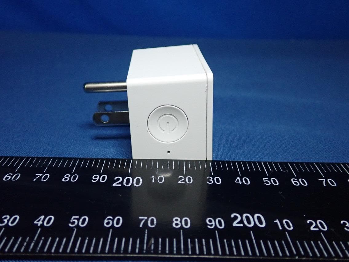
Q87-03457
Mar 10, 2020WEMO Smart Plug
Equipment Class
DTS - Digital Transmission System