Q87-BEFCMU10V3CABLE MODEM
LINKSYS LLC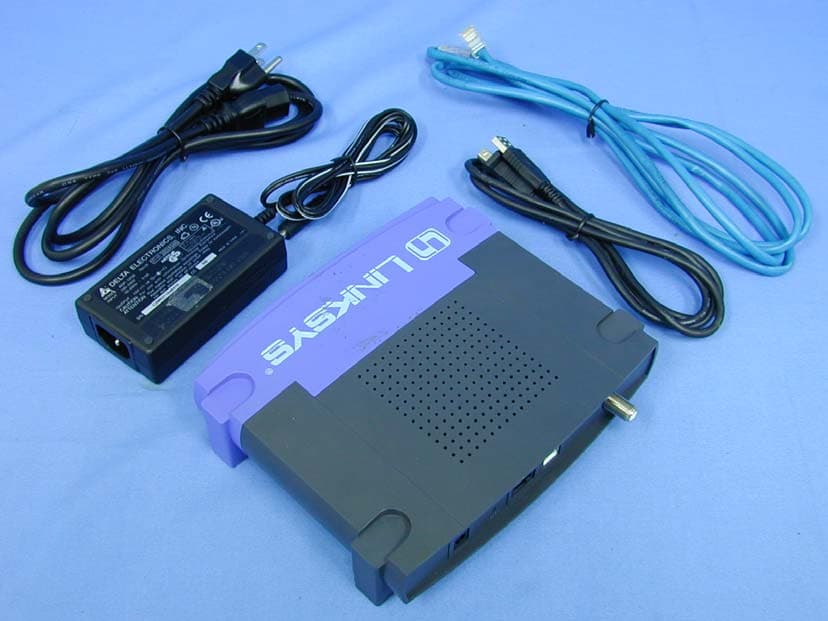
Click to zoom
Application Details
- Equipment Class
- JBP - Part 15 Class B Computing Device Peripheral
- Date of Grant
- Jul 08, 2003
- Application Purpose
- Original Equipment
- Date of Application
- Jul 08, 2003
- Equipment Note
- CABLE MODEM
- Company
- LINKSYS LLC
- Country
- United States
Documents & Files
Document Text
Text extracted from the exhibit documents filed with the FCC. Open a document above to read the original.
Users Manual
LINKSYS BEFCMU10 ver. 3 User Manual 2 LINKSYS BEFCMU10 ver. 3 Cable Modem User’s Manual LINKSYS BEFCMU10 ver. 3 User Manual Safety Notes For Installation Use only the type of power source indicated on the marking labels. Use only the power adapter supplied with the product. Do not overload wall outlet or extension cords as this may increase the risk of electric shock or file. If the power cord is frayed, replace it with a new one. Proper ventilation is necessary to prevent the product overheating. Do not block or cover the slots and openings on the device, which are intended for ventilation and proper operation. It is recommended to mount the product with a stack. Do not place the product near any source of heat or expose it to direct sunshine. Do not expose the product to moisture. Never spill any liquid on the product. Do not attempt to connect with any computer accessory or electronic product without instructions from qualified service personnel. This may result in risk of electronic shock or file. Do not place this product on an unstable stand or table. For Using Power off and unplug this product from the wall outlet when it is not in use or before cleaning. Pay attention to the temperature of the power adapter. The temperature might be high. After powering off the product, power on the product at least 15 seconds later. Do not block the ventilating openings of this product. When the product is expected to be not in use for a period of time, unplug the power cord of the product to prevent it from the damage of storm or sudden increases in rating. For Service Do not attempt to disassemble or open covers of this unit by yourself. Nor should you attempt to service the product yourself, which may void the user’s authority to operate it. Contact qualified service personnel under the following conditions: If the power cord or plug is damaged or frayed. If liquid has been spilled into the product. If the product has been exposed to rain or water. If the product does not operate normally when the operating instructions are followed. If the product has been dropped or the cabinet has been damaged. If the product exhibits a distinct change in performance. Warning This equipment must be installed and operated in accordance with provided instructions and a minimum 20 cm spacing must be provided between computer mounted antenna and person’s body (excluding extremities of hands, wrist and feet) during wireless modes of operation. This device complies with Part 15 of the FCC Rules. Operation is subject to the following two conditions: (1) this device may not cause harmful interference, and (2) this device must accept any interference received, including interference that may cause undesired operation. Caution Any changes or modifications not expressly approved by the party responsible for compliance could void the authority to operate equipment. LINKSYS BEFCMU10 ver. 3 User Manual 2 NOTE This equipment has been tested and found to comply with the limits for a Class B digital device, pursuant to part 15 of the FCC Rules.These limits are designed to provide reasonable protection against harmful interference in a residential installation.This equipment generates, uses and can radiate radio frequency energy and, if not installed and used in accordance with the instructions, may cause harmful interference to radio communications. However, there is no guarantee that interference will not occur in a particular installation. If this equipment does cause harmful interference to radio or television reception, which can be determined by turning the equipment off and on, the user is encouraged to try to correct the interference by one or more of the following measures: - Reorient or relocate the receiving antenna. - Increase the separation between the equipment and receiver. -Connect the equipment into an outlet on a circuit different from that to which the receiver is connected. -Consult the dealer or an experienced radio/TV technician for help. LINKSYS BEFCMU10 ver. 3 User Manual C C h h a a p p t t e e r r 1 1 : : O O v v e e r r v v i i e e w w 1.1 Physical Outlook 1 1 . . 1 1 - - 1 1 F F r r o o n n t t P P a a n n e e l l The following illustration shows the front panel of the LINKSYS BEFCMU10 VER. 3 Cable Modem. LED Indicators The LEDs on the front panel are described in the table below (from left to right): LED Color Status Description Off Power off. POWER Green On Power on. Off Power off or the initial test is over. Cable Green Blinking To indicate cable modem is on line. Off Power off or the initial test is over. Activity Green Blinking To indicate transmit RF US traffic. Off Power off or the initial test is over. Blinking To indicate Ethernet data traffic. Ethernet Green On Ethernet line is in use. Off Power off or the initial test is over. Blinking To indicate USB data traffic. USB Green On USB interface is in use. 1 1 . . 1 1 - - 2 2 R R e e a a r r P P a a n n e e l l 12 VDC: 12V Power connector RESET︰ Reset-to-Default push button LAN︰ 10/100BaseTX RJ-45 connectors USB: USB Connector LINKSYS BEFCMU10 ver. 3 User Manual CABLE︰ F-Connector LINKSYS BEFCMU10 ver. 3 User Manual C C h h a a p p t t e e r r 2 2 : : I I n n s s t t a a l l l l a a t t i i o o n n 2.1 Connecting the Cable Modem to Your Computer 2 2 . . 1 1 - - 1 1 I I n n s s t t a a l l l l a a t t i i o o n n P P r r o o c c e e d d u u r r e e f f o o r r E E t t h h e e r r n n e e t t I I n n t t e e r r f f a a c c e e Follow the steps below for proper installation: 1. Make sure your computer meets the system requirements. 2. Connect a coaxial cable (supplied by the local Cable Television Company) to the CABLE connector on the modem. 3. Plug the power adapter into the POWER connector of the modem. 4. Plug the other end of the power adapter into a power outlet. 5. Check CABLE LED. If it is solid ON, the Cable Modem is on-line now. If it is not, contact your service provider. 5. Connect the …
Text truncated - open the document above for the full version.
Block Diagram
BCM3348 DC 12V X’TAL 24MHz Power Jack EEPROM 24WC02 (Optional) 10/100BaseT 12VDC to 3.3VDC Switching Regulator SDRAM 4Mx16 FLASH 1Mx16 1 * 4 Wafer F-connector Diplexer Upstream Downstream BCM3401 + BCM3416 RF Transformer Console RJ-45 Connector Ethernet Transformer CME105-D40 Block Diagram USB Jack USB X6864D 3.3VDC to 1.2VDC (2SB772) 3.3VDC to 2.5VDC (2SB772) POWERCABLELANACTIVITYUSB
External Photos
Report No.: 036H064F Page : 1 of 9 Version : 1.0 Attachment 2 : EUT Detailed Photographs (1) EUT Photo (Mode 1) (2) EUT Photo Report No.: 036H064F Page : 6 of 9 Version : 1.0 (7) EUT Photo (Mode 2) (8) EUT Photo
ID Label/Location Info
Cisco-Linksys, LLC FCC ID.: Q87-BEFCMU10V3 17401 Armstrong Avenue, Irvine, CA 92614 USA Tel: 886 3-552-6588 FCC ID AND DoC Label The FCC ID and DoC Label will be placed on the equipment as shown in the photograph below. Cable Modem Linksys Model No.: BEFCMU10 ver.3 TESTED TO COMPLY WITH FCC STANDARDS FOR HOME OR OFFICE USE S/N: Made in Taiwan Cable Modem Model No.: BEFCMU10 ver.3 F F C C C C I I D D : : Q Q 8 8 7 7 - - B B E E F F C C M M U U 1 1 0 0 V V 3 3 This device complies with Part 15 of the FCC Rules. Operation is subject to the following two conditions: (1) this device may not cause harmful interference and (2) this device must accept any interference received, including interference that may cause undesired operation. S/N: Made in Taiwan
ID Label/Location Info
Cisco-Linksys, LLC FCC ID.: Q87-BEFCMU10V3 17401 Armstrong Avenue, Irvine, CA 92614 USA Tel: 886 3-552-6588 FCC ID AND DoC Label The FCC ID and DoC Label will be placed on the equipment as shown in the photograph below. Cable Modem Linksys Model No.: BEFCMU10 ver.3 TESTED TO COMPLY WITH FCC STANDARDS FOR HOME OR OFFICE USE S/N: Made in Taiwan Cable Modem Model No.: BEFCMU10 ver.3 F F C C C C I I D D : : Q Q 8 8 7 7 - - B B E E F F C C M M U U 1 1 0 0 V V 3 3 This device complies with Part 15 of the FCC Rules. Operation is subject to the following two conditions: (1) this device may not cause harmful interference and (2) this device must accept any interference received, including interference that may cause undesired operation. S/N: Made in Taiwan
Internal Photos
Report No.: 036H064F Page : 1 of 9 Version : 1.0 Attachment 2 : EUT Detailed Photographs (1) EUT Photo (Mode 1) (2) EUT Photo Report No.: 036H064F Page : 2 of 9 Version : 1.0 (3) EUT Photo Report No.: 036H064F Page : 3 of 9 Version : 1.0 (4) EUT Photo Report No.: 036H064F Page : 4 of 9 Version : 1.0 (5) EUT Photo Report No.: 036H064F Page : 5 of 9 Version : 1.0 (6) EUT Photo Report No.: 036H064F Page : 6 of 9 Version : 1.0 (7) EUT Photo (Mode 2) (8) EUT Photo Report No.: 036H064F Page : 7 of 9 Version : 1.0 (9) EUT Photo (10) EUT Photo Report No.: 036H064F Page : 8 of 9 Version : 1.0 (11) EUT Photo Report No.: 036H064F Page : 9 of 9 Version : 1.0 (12) EUT Photo
Schematics
AA BB CC DD EE 4 4 3 3 2 2 1 1 Place at 4 corners of BCM3415 PLL1 DVDD Dwncnvtr VDD PLL2 DVDD Place0.1ufclose to pin 5. Short lines Place0.01ufclose topin 4. Thin lines Short lines Put 0.01ufclose to pin40 AGC_inpin THESE COMPONENTS ARE WITHIN THE BOARD STIFFENER OUTLINE RF Input 54 - 860MHz +3.3VPOWERPLANE w=5 mi ls, s>15 mils, keep lines matchedand short Shield loop filter withground ring/lines AGC VDD Add many thermal vias (12 mildiam.) under chip. No soldermask under chip on top andbottom XTAL VDD Add many thermal vias (12 mildiam.) under chip. No solder maskunder chip on top and bottom Place 0.1uf and 22uFclose to pin 8. Input matching network Short lines VCO2 AVDD Upcn vtr VDD BAND GAP VDD TQFP48 pkg withdownset paddle PLL1 AVDD RF_DATA DS_IF_P US_OUTPUT DS_IF_N TUNER_AGC IF_AGC RF_CLK +3.3V_TUNER R R +3.3V_TUNER R R R R R R R R R R R R RR R R R R R R R R R R R R RR +3.3V_TUNER R R R R R R C16933PF L18 15nH_0402 C1975600PF C1641000PF C1911PF C1931000PF C1800.1UF L11100UH 12 R130_DNP_0402 C1812200uF/6.3V-E/C(LOW ESR) 12 C173DNP_cc 12 C224_DNP R94 160 1 2 RFGND5testpoint_040 1 TP R100160 12 L158.2NH 1 2 C183 0.01UF RFGND6testpoint_040 1 TP C1700.1UF R982.7K 12 L13 1.8NH 1 2 RFGND7testpoint_040 1 TP R1070 12 FB26BLM11A221S 12 C1631000PF C1780.1UF RFGND8testpoint_040 1 TP C1990.1UF C1940.01UF RFGND9testpoint_040 1 TP FB25 BLM11A221S 12 U13BCM3415B1 123456789 10 14 1211 15 16 17 18 19 20 21 22 23 24 252627282930313233343536 37 38 39 40 41 42 43 44 45 46 47 4813 AVDD_PLL1AGND_PLL1DGND_PLL1DVDD_PLL1RF_SHIELD1RFIN+RFIN-RF_SHIELD2VDD_1200_MIXGND_1200_MIX GND_IF_MIX RF_MIX_OUT+RF_MIX_OUT- IF_MIX_IN+ IF_MIX_IN- VDD_IF_MIX_AMP IF_MIX_AMP_OUT- IF_MIX_AMP_OUT+ GND_IF_MIX_AMP IF_VGA_IN- IF_VGA_IN+ ADDR0 SDA SCL ADDR1 CHRG_PMP_OUT PLL2_BIAS AVDD_PLL2 FILT_CHRG_PMP_OUT AGND_PLL2 PLL2_AUTO_TUNE DVDD_PLL2 DGND_PLL2 VDD_XTAL GND_XTAL XTAL2 XTAL1 GND_AGC AGC_IN VGA_OUT- VGA_OUT+ VDD_AGC VREF_BAND_GAP GND_BIAS_BND_GAP VDD_BND_GAP GND_ESD GND_PLL1VDD_IF_MIX U14BCM3401 3421 8765 CMLAGCRFINGND VDD RFOUT+ RFOUT- PWRDWN U15NJRC-01 12 4 3 8567910 DWNSTRM GND1 UPSTRM GND2 GND6GND3GND4GND5GND7GND8 C1710.1UF 12 C1660.1UF C185 0.1UF 1 2 C1980.18UF R96 1K 12 L19 22nH_0402 C2060.039UF C1861000PF R126 0_0402 L1222UH/ATPI0403Rdc = 0.6 ohms 1 2 C2010.1UF FB27 BLM11A601SPB 1 2 C1650.1UF C1670.01UF C204 8.2pF_0402 C1721UF/0805 12 C1680.01UF R127 0_0402 C17933PF C1741000PF C1901PF R921K 1 2 C2000.1UF U161220MHz LJ72C 21 8 5 7 3 6 4 IN2IN1 CASE OUT2 GND GND OUT1 CASE C1920.1UF C1760.1UF C203 2.2pF_0402 C2058.2pF_0402 C2070.039UF R93390 12 RFGND3testpoint_040 1 TP C1890.1UF R993K 12 + C18822UF/CCB RFGND2testpoint_040 1 TP C1870.5PF_DNP R128_DNP_0402 L1727NH 12 RFGND1testpoint_040 1 TP L143.9NH 1 2 C1950.1UF C1960.1UF C2022.2pF_0402 C1821000PF SAWFILTER U17X6964D 12 3 45 IN1IN2 GND OUT1OUT2 C2110.1UF C223 0.5PF R9510K 12 R108 0 12 C1750.1UF L16 1.8NH 1 2 R129_DNP_0402 Y3 10.000MHZ C1770.1UF FB24 BLM11A601SPB 1 2 R1011K 12 C1841000PF RFGND4testpoint_040 1 TP R97 160 1 2 AA BB CC DD EE 4 4 3 3 2 2 1 1 Place Transformerclose to Tuner tominimize single-endedsecondary trace length. NOTE: Route DACoutputs as matchedpair. Place Transformerclose to Diplexer tominimize single-endedsecondary trace length. Place these componentsnear the BCM3348. Place thesecomponentsnear theBCM3348. DSCLK_VDD DS_AGCI_CTL USPLL_DVDD DS_AGCT_CTL DS_AVDD USAMP_AVDDI USDAC_BIAS USDAC_AVDD USAMP_AVDDO DS_DVDDUSDAC_DVDD US_OE DSPGA_AVDDUSPLL_AVDDUSDAC_LVDD DS_IF_NDS_IF_P US_OUTPUT TUNER_AGCCABLE_ACTIVITY_LED_NIF_AGCRF_DATARF_CLK R +2.5V R +2.5V R R +12V +3.3V R R R +1.2V +2.5V R R +2.5V R R119 4.7K 12 FB22 BLM11A601SPB 1 2 R114 75 1 2 FB21 BLM11A601SPB 1 2 R79 0 1 2 FB15 BLM11A601SPB 1 2 FB23 BLM11A601SPB 1 2 BCM3348 DOCSIS MAC/PHY (4 OF 4) and TEST CLOCKS U4ABCM3348A0 AB26 K26J26K25K24AB23AC23M26B20N26N25N24P26P25P24A24H25G25R24R23M24L26 AD26 AC18AF21 AF23AF22AD21AD20 AC21AE22 B22B21 R26C26 A22 D25D26R25C21 A23 C22 A25 Y23 J25 G24 E24 E25 AC25 V23 F26 F24 AB24 W23 AA26AA25 AB25 AC19 AC20 AC24 G26 H26 Y25 J24 E26 F25 W24 Y24 Y26 AA23 AA24 US_PLL_AVDD_1P2 RFT_CLK RFT_DATA RFT_CS[0]RFT_CS[1] US_DAC_OUT(+) US_DAC_OUT(-) US_OE RF_BURST US_POWER[0]US_POWER[1]US_POWER[2]US_POWER[3]US_POWER[4]US_POWER[5] CABLE_LED_N DS_AFE_QAM(+) DS_AFE_QAM(-) DS_AGCI_CTL DS_AGCT_CTL DS_BCLK DS_ADCLK US_DAC_IBIAS USAMP_AVSSOUSAMP_AVDDO_2P5 USAMP_IN(+) USAMP_IN(-) USAMP_OUT(+) USAMP_OUT(-) USAMP_AVSSIUSAMP_AVDDI_2P5 TEST_ENABLESCAN_MODESYSPLL_BYPCLK25M_BYPPERIPH_TEST_CLKMIPS_TEST_CLKSYS_TEST_CLKUS_TEST_CLKUSB_TEST_CLKEPHY_TEST_CLKEPHYPLL_BYP25M_TEST_CLK US_DAC_LDVDD_1P2 DS_AFE_PGA_AVDD_2P5 DS_AFE_AVDD_1P2 DS_AFE_CLK_VDD_2P5 DS_AFE_DVDD_1P2 US_DAC_AVDD_2P5 US_DAC_DVDD_2P5 DS_AFE_AVSS DS_AFE_DVSS US_DAC_AVSS US_DAC_DVSS US_PLL_AVSSUS_PLL_DVDD_1P2 US_PLL_DVSS USAMP_AVSSO USAMP_AVSSO US_DAC_AVSS DS_AFE_AVSS DS_AFE_AVSS US_PLL_DVDD_1P2 DS_AFE_AVDD_1P2 DS_AFE_CLK_VDD_2P5 DS_AFE_CLK_VDD_2P5 AVSS AVSS AVSS AVSS AVSS C1361UF_10V 12 C1270.33uF 12 R882.7K 12 R113 75 1 2 R78 1K 1 2 C1191000PF 12 C1230.1UF_DNP 12 C1341UF_10V 12 P1 & P2 TP-DIFFERENTIAL C217DNP_cc 12 C1715P_DNP 1 2 R112 110 1 2 C1390.01UF 12 R76 1K 1 2 C2190.1UF 12 D12 BAV99/SOT 3 1 2 FB13 BLM11A601SPB 1 2 FB14 BLM11A601SPB 1 2 C1250.33uf 12 TP1 1 TP C1351000PF 12 C2180.1UF 12 C1381UF 12 R111 110 1 2 C1151000PF 12 R109 0 1 2 R91 2.7K 12 C216 10PF 1 2 C2140.1UF 12 + C213 220uF/10V-E/C D13 BAV99/SOT 3 1 2 R120 4.7K 12 C1124.7UF_10V 12 FB20 BLM11A601SPB 1 2 L20 100UH 1 2 R77 0 1 2 C1331000PF 12 C1131000PF 12 L8 ARI235TR0502T,1CT:1 1 65 3 4 2 C1291000PF 12 C1144.7UF_10V 12 R110 DNP 1 2 C1160.1UF 12 D14 BAV99/SOT 3 1 2 R89 2.7K 12 C1170.1UF_DNP 12 C220 0.1UF 12 C215 10PF 1 2 L21 0 12 FB18 BLM11A601SPB 1 2 R804.12K1% 12 R90 2.7K 12 FB16 BLM11A601SPB 1 2 + C140 10uF/10V/CCA C1371000PF 12 FB17 BLM11A601SPB 1 2 C1311000Pf 12 C1220.1UF 12 FB19 BLM11A601SPB 1 2 C1211000PF 12 C2120.1UF 12 C715P_DNP 1 2 AA BB CC DD EE 4 4 3 3 2 2 1 1 USBActivityLANCABLE Power GPIO5 GPIO20 GPIO26 GPIO19GPIO10GPIO11GPIO18 CABLE_ACTIVITY_LED_N GPIO21 GPIO12 EPHY…
Text truncated - open the document above for the full version.
Test Report
Report No. 036H064FI Page : 1 of 21 Version:1.0 Test Report Product Name: Cable Modem Model No.: BEFCMU10 ver.3 FCC ID. : Q87-BEFCMU10V3 Applicant : Cisco-Linksys, LLC Address : 17401 Armstrong Avenue, Irvine, CA 92614 USA Date of Receipt : Jun. 19, 2003 Date of Test : Jun. 24, 2003 Report No. : 036H064FI The test results relate only to the samples tested. The test report shall not be reproduced except in full without the written approval of QuieTek Corporation. This report must not be used to claim product endorsement by NVLAP any agency of the U.S. Government Report No. 036H064FI Page : 2 of 21 Version:1.0 Test Report Certification Test Date : Jun. 24, 2003 Report No. : 036H064FI Product Name : Cable Modem Applicant : Cisco-Linksys, LLC Address : 17401 Armstrong Avenue, Irvine, CA 92614 USA Manufacturer : ASKEY COMPUTER CORP. Model No. : BEFCMU10 ver.3 FCC ID. : Q87-BEFCMU10V3 Rated Voltage : AC 120V/60Hz Trade Name : Linksys Measurement Standard : FCC Part 15 Subpart B: 2002, CISPR 22:1997. Measurement Procedure : ANSI C63.4: 1992 Classification : Class B Test Result : Complied The Test Results relate only to the samples tested. The test report shall not be reproduced except in full without the written approval of QuieTek Corporation. This report must not be used to claim product endorsement by NVLAP any agency of the U.S. Government Documented By : ( Lydia Tsai ) Tested By : (Allen Wu ) Approved By : ( Kevin Wang ) Accredited by NIST (NVLAP) NVLAP Lab Code: 200347-0 Report No. 036H064FI Page : 3 of 21 Version:1.0 TABLE OF CONTENTS Description Page 1. GENERAL INFORMATION ....................................................................................................4 1.1. EUT Description...........................................................................................................................4 1.2. Tested System Details...................................................................................................................5 1.3. Configuration of tested System ....................................................................................................6 1.4. EUT Exercise Software ................................................................................................................6 1.5. Test Facility ..................................................................................................................................7 2. Conducted Emission...................................................................................................................8 2.1. Test Equipment.............................................................................................................................8 2.2. Test Setup .....................................................................................................................................8 2.3. Limits ...........................................................................................................................................9 2.4. Test Procedure ..............................................................................................................................9 2.5. Test Result ....................................................................................................................................9 3. Radiated Emission ....................................................................................................................10 3.1. Test Equipment...........................................................................................................................10 3.2. Test Setup ...................................................................................................................................10 3.3. Limits .........................................................................................................................................11 3.4. Test Procedure ............................................................................................................................11 3.5. Test Result ..................................................................................................................................11 4. EMI Reduction Method During Compliance Testing ...........................................................12 5. Summary of Test Datas ............................................................................................................13 5.1. Test Data of conducted Emission ...............................................................................................14 5.2 Test Data of Radiated Emission...............................................................................................................18 Attachment 1: EUT Test Photographs Attachment 2: EUT Detailed Photographs Report No. 036H064FI Page : 4 of 21 Version:1.0 1. GENERAL INFORMATION 1.1. EUT Description Product Name : Cable Modem Trade Name : Linksys Model No. : BEFCMU10 ver.3 FCC ID. : Q87-BEFCMU10V3 USB Cable : Non-shielded, 1.5m LAN Cable : Non-shielded, 3.0m Power Adapter (Mode1) : OEM, AD-121ANDT Cable IN: Non-shielded, 1.9m Cable Out: Non-shielded, 1.9m Power Adapter (Mode2) : DELTA, ADP-12SB Rev. B Cable Out: Non-shielded, 1.8m Power Cord : Non-shielded, 1.8m Note: 1. This EUT is a Cable Modem. 2. QuieTek has verified both construction and function in typical operation. All the test modes were carried out with the EUT in normal operation, which was shown in this test report and defined as: EMI Mode: Mode 1: Cable Modem OEM AD-121ANDT Mode 2: Cable Modem DELTA ADP-12SB Rev. B Report No. 036H064FI Page : 5 of 21 Version:1.0 1.2. Tested System Details The types for all equipment, plus descriptions of all cables used in the tested system (including inserted cards) are: Product ManufacturerModel No. Serial No. Power Cord (1) PC HP DTPC27 SG21200950 Non-shielded, 1.8m (2) Monitor LEMEL VA-570 OS243014320 Non-shielded, 1.8m (3) Keyboard ACER 6311-TW4C/6N/A -- (4) Mouse Logitech M-S35 LZA749563…
Text truncated - open the document above for the full version.
Test Setup Photos
Report No.: 036H064F Page : 1 of 4 Version:1.0 Attachment 1 : EUT Test Photographs Front View of Conducted Test (Mode 1) Back View of Conducted Test (Mode 1) Report No.: 036H064F Page : 2 of 4 Version:1.0 Front View of Conducted Test (Mode 2) Back View of Conducted Test (Mode2) Report No.: 036H064F Page : 3 of 4 Version:1.0 Front View of Radiated Test (Mode 1) Back View of Radiated Test (Mode 1) Report No.: 036H064F Page : 4 of 4 Version:1.0 Front View of Radiated Test (Mode 2) Back View of Radiated Test (Mode 2)
Contact Information
Applicant
Po-Wen Cheng(Regulatory Compliance Manager)
Test Firm
DEKRA Testing and Certification Co., Ltd.Sky Hsu
Technical Specifications
| # | Rule Parts | Frequency Range | Power Output |
|---|---|---|---|
| 1 | 15B | - | - |
Other Applications from LINKSYS LLC

Q87-WDS060
Aug 11, 2020WiFi Smart Light Switch with Dimmer
Equipment Class
DTS - Digital Transmission System
Q87-03564
Jun 28, 2020Linksys Tri-Band Wireless-AC Router
Equipment Class
NII - Unlicensed National Information Infrastructure TX
Q87-03566
Jun 23, 2020Linksys Tri-Band Wireless-AC Router
Equipment Class
NII - Unlicensed National Information Infrastructure TX
Q87-03530
Apr 29, 2020Linksys MAX-STREAM AC1900+ WiFi Range Extender
Equipment Class
NII - Unlicensed National Information Infrastructure TX
Q87-08151
Mar 30, 2020Linksys Dual-Band 802.11ax Wireless Router
Equipment Class
DTS - Digital Transmission System