Q87-EA4500802.11 a/b/g/n AP
LINKSYS LLC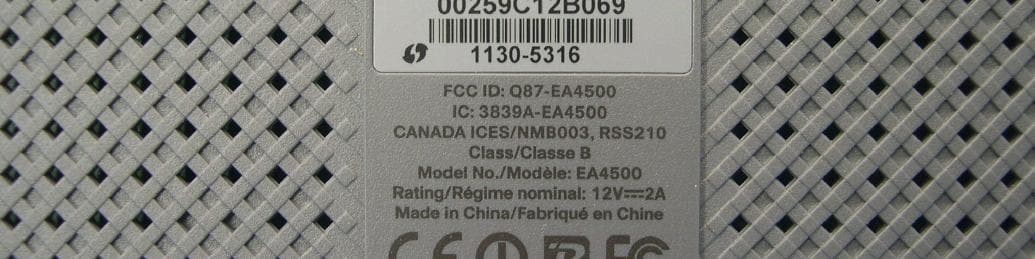
Click to zoom
Application Details
- Equipment Class
- NII - Unlicensed National Information Infrastructure TX
- Date of Grant
- Feb 01, 2012
- Application Purpose
- Original Equipment
- Date of Application
- Feb 01, 2012
- Equipment Note
- 802.11 a/b/g/n AP
- Frequency Range
- 5180.00000000 - 5240.00000000
- Company
- LINKSYS LLC
- Country
- United States
Documents & Files
Document Text
Text extracted from the exhibit documents filed with the FCC. Open a document above to read the original.
Users Manual
Linksys EA-Series Routers Linksys EA-Series Table of Contents Table of Contents Product overview EA2700/EA3500 Back view Bottom view Wireless Security 1 1 1 Wireless > Wireless Security Personal options Office options Option settings 8 8 8 8 EA4500 Top view Back view 2 2 2 Troubleshooting How to run Cisco Connect after setup Your router was not successfully set up Get Windows XP Service Pack 3 message Your Internet cable is not plugged in message Cannot access your router message Device not found message 11 12 12 13 14 15 Setting Up Your EA-Series Router Where to find more help How to set up your router How to start Cisco Connect Use Cisco Connect to manage your router 3 3 3 3 How to manually set up your router 3 Advanced Configuration How to open the browser-based utility Setup > Basic Setup Language Internet Setup Specifications 4 5 5 5 Wireless > Basic Wireless Settings Wireless Settings 6 6 Linksys EA2700 Linksys EA3500 Linksys EA4500 17 18 19 i Linksys EA-Series Product overview • Product overview EA2700/EA3500 Back view Power indicator—Stays on steadily while power is connected and following a successful Wi-Fi Protected Setup connection Flashes slowly during bootup, during firmware upgrades, and during a Wi-Fi Protected Setup connection Flashes quickly when there is a Wi-Fi Protected Setup error Power—Connect the included AC power adapter to this port CAUTION Use only the adapter that came with your router • • Power button—Press | (on) to turn on the router Bottom view Power port USB port (EA3500 only) Ethernet ports Internet port Power indicator Wi-Fi Protected Setup button Your router’s appearance may vary • • USB port (EA3500 only)—To easily share disk storage with other users on your network or on the Internet, connect a USB drive to this port Ethernet ports—Connect Ethernet cables (also called network cables) to these Fast Ethernet (10/100, for E1200 and E1500) or Gigabit (10/100/1000, for EA2700 and EA3500) ports, color coded blue, and to other wired Ethernet network devices on your network Internet port—Connect an Ethernet cable (also called a network or Internet cable) to this port, color coded yellow, and to your modem Wi-Fi Protected Setup™ button—Press this button to easily configure wireless security on Wi-Fi Protected Setup-enabled network devices For more information, see ―Wireless Security‖ on page 8 • Your router’s appearance may vary • Reset button—Press and hold this button for 5-10 seconds (until the port lights flash at the same time) to reset the router to its factory defaults You can also restore the defaults using the browser-based utility 1 Linksys EA-Series Product overview Back view EA4500 Top view Ethernet ports Internet port Wi-Fi Protected Setup button Power port Reset button USB port • Indicator light Ethernet ports—Connect Ethernet cables (also called network cables) to these Gigabit (10/100/1000) ports, color coded blue, and to other wired Ethernet network devices on your network Internet port—Connect an Ethernet cable (also called a network or Internet cable) to this port, color coded yellow, and to your modem Wi-Fi Protected Setup™ button—Press this button to easily configure wireless security on Wi-Fi Protected Setup-enabled network devices For more information, see ―Wireless Security‖ on page 8 USB port—To easily share disk storage with other users on your network or on the Internet, connect a USB drive to this port Reset button—Press and hold this button for 5-10 seconds (until the port lights flash at the same time) to reset the router to its factory defaults You can also restore the defaults using the browser-based utility Power—Connect the included AC power adapter to this port CAUTION Use only the adapter that came with your router • • • Indicator light—Stays on steadily while power is connected and following a successful Wi-Fi Protected Setup connection Pulses slowly during bootup, during firmware upgrades, and during a Wi-Fi Protected Setup connection Flashes quickly when there is a Wi-Fi Protected Setup error • • • • Power button—Press | (on) to turn on the router 2 Linksys EA-Series Setting Up Your EA-Series Router Setting Up Your EA-Series Router Where to find more help In addition to this User Guide, you can find help at these locations: • • • To start Cisco Connect for the first time: 1 . Insert the CD into your CD or DVD drive 2 . Click Set up your Linksys Router If you do not see this: • • Linksys.com/support (documentation, downloads, FAQs, technical support, live chat, forums) Cisco Connect help (run Cisco Connect, then click Learn More where available) Browser-based utility context-sensitive help (open the utility, then click Help in the right-side column ) For Windows, click Start, Computer, then double-click the CD drive and the Setup icon For Mac, double-click the CD icon on your desktop, then double-click the Setup icon 3 . Follow the on-screen instructions to complete your router setup How to set up your router The easiest and fastest way to set up your router is to run the Cisco Connect setup software Use Cisco Connect to manage your router After your router has been set up and Cisco Connect has been installed, you can use Cisco Connect to easily manage many of your router’s settings such as: • • • • • How to start Cisco Connect When you run the setup CD, Cisco Connect (your router’s setup software) is automatically installed onto your computer You can then use Cisco Connect to easily manage your router NOTE: If you lose your setup CD, you can download the software from Linksys.com/support Connect devices to your network Test your Internet connection speed Configure parental controls Set up guest access Change your router’s name and password How to manually set up your router After setting up the router with the setup software (located on the CD), the router will be ready for use If you would like to change its advanced settings, or if the software does not run, use the router’s browser-based utility You can access the util…
Text truncated - open the document above for the full version.
Users Manual
Linksys Dual-Band N Routers and Bridges Regulatory Information i Linksys Dual-Band N Routers and Bridges Table of Contents Wireless Regulatory Information 1 FCC Statement 1 FCC Radiation Exposure Statement 1 Safety Notices 1 Industry Canada Statement 1 Avis d’Industrie Canada 1 Wireless Disclaimer 2 Avis de non-responsabilité concernant les appareils sans fil 2 Declaration of Conformity with Regard to EU Directive 1999/5/EC (R&TTE Directive) 2 Wireless Equipment (Wireless-N/G/A/B Products) 3 National Restrictions 3 Product Usage Restrictions 4 Technical Documents on http://home cisco com/wireless 4 WEEE Information 5 User Information for Consumer Products Covered by EU Directive 2002/96/EC on Waste Electric and Electronic Equipment (WEEE) 5 1 Linksys Dual-Band N Routers and Bridges Wireless Regulatory Information FCC Statement This device complies with Part 15 of the FCC Rules Operation is subject to the following two conditions: (1) This device may not cause harmful interference, and (2) this device must accept any interference received, including interference that may cause undesired operation This product has been tested and complies with the specifications for a Class B digital device, pursuant to Part 15 of the FCC Rules These limits are designed to provide reasonable protection against harmful interference in a residential installation This equipment generates, uses, and can radiate radio frequency energy and, if not installed and used according to the instructions, may cause harmful interference to radio communications However, there is no guarantee that interference will not occur in a particular installation If this equipmen t does cause harmful interference to radio or television reception, which is found by turning the equipment off and on, the user is encouraged to try to correct the interference by one or more of the following measures: •Reorient or relocate the receiving antenna •Increase the separation between the equipment or devices •Connect the equipment to an outlet other than the receiver’s •Consult a dealer or an experienced radio/TV technician for assistance FCC Caution: Any changes or modifications not expressly approved by the party responsible for compliance could void the user’s authority to operate this equipment IEEE 802 11b or 802 11g operation of this product in the USA is firmware-limited to channels 1 through 11 The device for the band 5150-5250 MHz is only for indoor usage to reduce the potential for harmful interference to co-channel mobile satellite systems FCC Radiation Exposure Statement This equipment complies with FCC radiation exposure limits set forth for an uncontrolled environment This equipment should be installed and operated with minimum distance 20 cm between the radiator and your body This transmitter must not be co-located or operating in conjunction with any other antenna or transmitter Safety Notices WARNING: Do not use this product near water, for example, in a wet basement or near a swimming pool WARNING: Avoid using this product during an electrical storm There may be a remote risk of electric shock from lightning WARNING: This product contains lead, known to the State of California to cause cancer, and birth defects or other reproductive harm Wash hands after handling Industry Canada Statement This Class B digital apparatus complies with Canadian ICES-003 and RSS210 Operation is subject to the following two conditions: 1 This device may not cause inter ference and 2 This device must accept any interference, including interference that may cause undesired operation of the device Industry Canada Radiation Exposure Statement This equipment complies with IC radiation exposure limits set forth for an uncontrolled environment This equipment should be installed and operated with minimum distance 20 cm between the radiator & your body This transmitter must not be co-located or operating in conjunction with any other antenna or transmitter Restrictions in the 5 GHz Band The device for the band 5150-5250 MHz is only for indoor usage to reduce potential for harmful interference to co- channel mobile satellite systems Because high power radars are allocated as primary users (meaning they have priority) in 5250-5350 MHz and 5650-5850 MHz, these radars could cause interference and/or damage to licensed exempt LAN devices Additional requirements for the band 5600-5650 MHz: Until further notice, devices subject to this Section shall not be capable of transmitting in the band 5600- 5650 MHz, so that Environment Canada weather radars operating in this band are protected 2 Linksys Dual-Band N Routers and Bridges Avis d’Industrie Canada Cet appareil numérique de la classe B est conforme aux normes NMB-003 et RSS210 du Canada L’utilisation de ce dispositif est autorisée seulement aux conditions suivantes : 1 il ne doit pas produire de brouillage et 2 il doit accepter tout brouillage radioélectrique reçu, même si ce brouillage est susceptible de compromettre le fonctionnement du dispositif Avis d’Industrie Canada concernant l’exposition aux radiofréquences Ce matériel est conforme aux limites établies par IC en matière d’exposition aux radiofréquences dans un environnement non contrôlé Ce matériel doit être installé et utilisé à une distance d’au moins 20 cm entre l’antenne et le corps de l’utilisateur L’émetteur ne doit pas être placé près d’une autre antenne ou d’un autre émetteur, ou fonctionner avec une autre antenne ou un autre émetteur Restrictions dans la bande 5 GHz L’appareil pour la bande de 5150 à 5250 MHz est conçu pour usage à l’intérieur seulement afin de réduire le potentiel d’interférences pour les systèmes mobiles par satellite qui utilisent le même canal Du fait que les radars haute puissance ont la priorité dans les bandes 5250-5350 MHz et 5650-5850 MHz, ils pourraient causer des interférences ou endommager les périphériques réseau sans fil Autres restrictions pour la bande 5 600-5 650 MHz : sauf avis contraire, les périphériques concer…
Text truncated - open the document above for the full version.
External Photos
Report No.: 110714C16D 1 Report Format Version 4.0.0 Reference No. : 111220C05 CONSTRUCTION PHOTOS OF EUT Model No.: EA4500 Report No.: 110714C16D 2 Report Format Version 4.0.0 Reference No. : 111220C05 Report No.: 110714C16D 3 Report Format Version 4.0.0 Reference No. : 111220C05 Module No.: CAD2412 Report No.: 110714C16D 4 Report Format Version 4.0.0 Reference No. : 111220C05 Module No.: MU24-B120200-A1 Report No.: 110714C16D 5 Report Format Version 4.0.0 Reference No. : 111220C05
ID Label/Location Info
Label location 3521-9637 CVR01K206810 30mm x 2mm 687F74228146 30mm x 2mm
Internal Photos
Report No.: 110714C16D 1 Report Format Version 4.0.0 Reference No. : 111220C05 CONSTRUCTION PHOTOS OF EUT Model No.: EA4500 Report No.: 110714C16D 2 Report Format Version 4.0.0 Reference No. : 111220C05 Report No.: 110714C16D 3 Report Format Version 4.0.0 Reference No. : 111220C05 Report No.: 110714C16D 4 Report Format Version 4.0.0 Reference No. : 111220C05 Report No.: 110714C16D 5 Report Format Version 4.0.0 Reference No. : 111220C05
RF Exposure Info
Report No.: SA110714C16D Report Format Version 4.0.0 Reference No. : 111220C05 1 RF EXPOSURE REPORT REPORT NO.: SA110714C16D MODEL NO.: EA4500 FCC ID: Q87-EA4500 APPLICANT: Cisco Consumer Products LLC ADDRESS: 121 Theory Drive Irvine California 92617 United States ISSUED BY: Bureau Veritas Consumer Products Services (H.K.) Ltd., Taoyuan Branch Hsin Chu Laboratory LAB ADDRESS: No. 81-1, Lu Liao Keng, 9th Ling,Wu Lung Tsuen, Chiung Lin Hsiang, Hsin Chu Hsien 307, Taiwan This test report consists of 9 pages in total. It may be duplicated completely for legal use with the approval of the applicant. It should not be reproduced, except in full, without the written approval of our laboratory. The client should not use it to claim product certification, approval or endorsement by any government agency. The test results in the report only apply to the tested sample. Report No.: SA110714C16D Report Format Version 4.0.0 Reference No. : 111220C05 2 TABLE OF CONTENTS RELEASE CONTROL RECORD....................................................................................3 1. CERTIFICATION..............................................................................................4 2. RF EXPOSURE LIMIT.....................................................................................5 3. MPE CALCULATION FORMULA.....................................................................5 4. CLASSIFICATION............................................................................................5 5. CALCULATION RESULT OF MAXIMUM CONDUCTED POWER...................7 Report No.: SA110714C16D Report Format Version 4.0.0 Reference No. : 111220C05 3 RELEASE CONTROL RECORD ISSUE NO. REASON FOR CHANGE DATE ISSUED SA110714C16D Original release Jan. 10, 2012 Report No.: SA110714C16D Report Format Version 4.0.0 Reference No. : 111220C05 4 1. CERTIFICATION PRODUCT: 802.11 a/b/g/n AP MODEL: EA4500 BRAND: Cisco APPLICANT: Cisco Consumer Products LLC TEST SAMPLE: ENGINEERING SAMPLE STANDARDS: FCC Part 2 (Section 2.1091) FCC OET Bulletin 65, Supplement C (01-01) IEEE C95.1 The above equipment (Model: EA4500) has been tested by Bureau Veritas Consumer Products Services (H.K.) Ltd., Taoyuan Branch, and found compliance with the requirement of the above standards. The test record, data evaluation & Equipment Under Test (EUT) configurations represented herein are true and accurate accounts of the measurements of the sample’s EMC characteristics under the conditions specified in this report. PREPARED BY : , DATE: Jan. 10, 2012 ( Phoenix Huang, Specialist ) APPROVED BY : , DATE: Jan. 10, 2012 (May Chen, Deputy Manager ) Report No.: SA110714C16D Report Format Version 4.0.0 Reference No. : 111220C05 5 2. RF EXPOSURE LIMIT LIMITS FOR MAXIMUM PERMISSIBLE EXPOSURE (MPE) FREQUENCY RANGE (MHz) ELECTRIC FIELD STRENGTH (V/m) MAGNETIC FIELD STRENGTH (A/m) POWER DENSITY (mW/cm 2 ) AVERAGE TIME (minutes) LIMITS FOR GENERAL POPULATION / UNCONTROLLED EXPOSURE 300-1500 ... ... F/1500 30 1500-100,000 ... ... 1.0 30 F = Frequency in MHz 3. MPE CALCULATION FORMULA Pd = (Pout*G) / (4*pi*r 2 ) where Pd = power density in mW/cm 2 Pout = output power to antenna in mW G = gain of antenna in linear scale Pi = 3.1416 R = distance between observation point and center of the radiator in cm 4. CLASSIFICATION The antenna of this product, under normal use condition, is at least 20cm away from the body of the user. So, this device is classified as Mobile Device. Report No.: SA110714C16D Report Format Version 4.0.0 Reference No. : 111220C05 6 5. ANTENNA GAIN There are six antennas provided to this EUT, please refer to the following table: For 2.4GHz Transmitter Circuit Freq.(MHz) Peak Gain (dBi) Antenna Type Connecter Type 2400 3.31 PIFA UFL 2450 2.27 PIFA UFL Chain (0) 2500 2.27 PIFA UFL 2400 3.45 PIFA UFL 2450 2.99 PIFA UFL Chain (1) 2500 2.81 PIFA UFL 2400 1.82 PIFA UFL 2450 1.96 PIFA UFL Chain (2) 2500 1.85 PIFA UFL For 5GHz Transmitter Circuit Freq.(MHz) Peak Gain (dBi) Antenna Type Connecter Type 5150 3.71 PIFA UFL 5350 3.05 PIFA UFL 5600 3.00 PIFA UFL 5730 3.39 PIFA UFL Chain (0) 5850 3.62 PIFA UFL 5150 3.28 PIFA UFL 5350 3.60 PIFA UFL 5600 3.29 PIFA UFL 5730 2.95 PIFA UFL Chain (1) 5850 2.65 PIFA UFL 5150 3.71 PIFA UFL 5350 3.40 PIFA UFL 5600 3.71 PIFA UFL 5730 4.27 PIFA UFL Chain (2) 5850 3.91 PIFA UFL The EUT incorporates CDD function with 802.11a, 802.11b, 802.11g. Report No.: SA110714C16D Report Format Version 4.0.0 Reference No. : 111220C05 7 6. CALCULATION RESULT OF MAXIMUM CONDUCTED POWER For 15.247(2.4GHz): 802.11b: FREQUENCY BAND (MHz) MAX POWER (mW) ANTENNA GAIN (dBi) DISTANCE (cm) POWER DENSITY (mW/ cm 2 ) LIMIT (mW/cm 2 ) 2412-2462 314.3 7.7 20 0.368 1.00 Directional gain = 10 log[(10 G1/20 + 10 G2/20 + 10 G3/20 ) 2 / 3] Effective Legacy Gain (dBi) = 7.7 802.11g: FREQUENCY BAND (MHz) MAX POWER (mW) ANTENNA GAIN (dBi) DISTANCE (cm) POWER DENSITY (mW/ cm 2 ) LIMIT (mW/cm 2 ) 2412-2462 314.9 7.7 20 0.369 1.00 Directional gain = 10 log[(10 G1/20 + 10 G2/20 + 10 G3/20 ) 2 / 3] Effective Legacy Gain (dBi) = 7.7 802.11n(20MHz): FREQUENCY BAND (MHz) MAX POWER (mW) ANTENNA GAIN (dBi) DISTANCE (cm) POWER DENSITY (mW/ cm 2 ) LIMIT (mW/cm 2 ) 2412-2462 682.2 3.5 20 0.304 1.00 802.11n(40MHz): FREQUENCY BAND (MHz) MAX POWER (mW) ANTENNA GAIN (dBi) DISTANCE (cm) POWER DENSITY (mW/ cm 2 ) LIMIT (mW/cm 2 ) 2422-2452 171.4 3.5 20 0.076 1.00 Report No.: SA110714C16D Report Format Version 4.0.0 Reference No. : 111220C05 8 For 15.247(5GHz): 802.11a: FREQUENCY BAND (MHz) MAX POWER (mW) ANTENNA GAIN (dBi) DISTANCE (cm) POWER DENSITY (mW/ cm 2 ) LIMIT (mW/cm 2 ) 5745 ~ 5825 434.6 8.4 20 0.598 1.00 Directional gain = 10 log[(10 G1/20 + 10 G2/20 + 10 G3/20 ) 2 / 3] Effective Legacy Gain (dBi) = 8.4 802.11n(20MHz): FREQUENCY BAND (MHz) MAX POWER (mW) ANTENNA GAIN (dBi) DISTANCE (cm) POWER DENSITY (mW/ cm 2 ) LIMIT (mW/cm 2 ) 5745 ~ 5825 431.0 4.3 20 0.231 1.00 802.11n(40MHz): FREQUENCY BAND (MHz) MAX POWER (mW) ANTENNA GAIN (dBi) DISTANCE (cm) POWER DENSITY (mW/ cm…
Text truncated - open the document above for the full version.
Test Report
Report No.: RF110714C16D 1 Report Format Version 4.0.0 Reference No. : 111220C05 FCC TEST REPORT (15.247) REPORT NO.: RF110714C16D MODEL NO.: EA4500 FCC ID: Q87-EA4500 RECEIVED: July 26, 2011 TESTED: July 26 to Aug. 09, 2011 ISSUED: Jan. 10, 2012 APPLICANT: Cisco Consumer Products LLC ADDRESS: 121 Theory Drive Irvine California 92617 United States ISSUED BY: Bureau Veritas Consumer Products Services (H.K.) Ltd., Taoyuan Branch Hsin Chu Laboratory LAB ADDRESS : No. 81-1, Lu Liao Keng, 9th Ling,Wu Lung Tsuen, Chiung Lin Hsiang, Hsin Chu Hsien 307, Taiwan TEST LOCATION (1): No. 81-1, Lu Liao Keng, 9th Ling,Wu Lung Tsuen, Chiung Lin Hsiang, Hsin Chu Hsien 307, Taiwan TEST LOCATION (2): No. 49, Ln. 206, Wende Rd., Shangshan Tsuen, Chiung Lin Hsiang, Hsin Chu Hsien 307, Taiwan This test report consists of 123 pages in total. It may be duplicated completely for legal use with the approval of the applicant. It should not be reproduced except in full, without the written approval of our laboratory. The client should not use it to claim product certification, approval, or endorsement by TAF or any government agencies. The test results in the report only apply to the tested sample. Report No.: RF110714C16D 2 Report Format Version 4.0.0 Reference No. : 111220C05 Table of Contents RELEASE CONTROL RECORD........................................................................................5 1. CERTIFICATION....................................................................................................6 2. SUMMARY OF TEST RESULTS............................................................................7 2.1 MEASUREMENT UNCERTAINTY..........................................................................9 3. GENERAL INFORMATION...................................................................................10 3.1 GENERAL DESCRIPTION OF EUT.....................................................................10 3.2 DESCRIPTION OF TEST MODES.......................................................................13 3.2.1 TEST MODE APPLICABILITY AND TESTED CHANNEL DETAIL........................14 3.3 GENERAL DESCRIPTION OF APPLIED STANDARDS.......................................17 3.4 DESCRIPTION OF SUPPORT UNITS..................................................................18 3.5 CONFIGURATION OF SYSTEM UNDER TEST...................................................19 4. TEST TYPES AND RESULTS (2400 ~ 2483.5MHz Band)....................................21 4.1 CONDUCTED EMISSION MEASUREMENT........................................................21 4.1.1 LIMITS OF CONDUCTED EMISSION MEASUREMENT......................................21 4.1.2 TEST INSTRUMENTS..........................................................................................21 4.1.3 TEST PROCEDURES..........................................................................................22 4.1.4 DEVIATION FROM TEST STANDARD.................................................................22 4.1.5 TEST SETUP.......................................................................................................23 4.1.6 EUT OPERATING CONDITIONS.........................................................................23 4.1.7 TEST RESULTS (MODE 1)..................................................................................24 4.1.8 TEST RESULTS (MODE 2)..................................................................................26 4.2 RADIATED EMISSION MEASUREMENT.............................................................28 4.2.1 LIMITS OF RADIATED EMISSION MEASUREMENT...........................................28 4.2.2 TEST INSTRUMENTS..........................................................................................29 4.2.3 TEST PROCEDURES..........................................................................................31 4.2.4 DEVIATION FROM TEST STANDARD.................................................................31 4.2.5 TEST SETUP.......................................................................................................32 4.2.6 EUT OPERATING CONDITIONS.........................................................................32 4.2.7 TEST RESULTS...................................................................................................33 4.3 6dB BANDWIDTH MEASUREMENT....................................................................62 4.3.1 LIMITS OF 6dB BANDWIDTH MEASUREMENT..................................................62 4.3.2 TEST INSTRUMENTS..........................................................................................62 4.3.3 TEST PROCEDURE.............................................................................................62 4.3.4 DEVIATION FROM TEST STANDARD.................................................................62 4.3.5 TEST SETUP.......................................................................................................62 4.3.6 EUT OPERATING CONDITIONS.........................................................................62 4.3.7 TEST RESULTS...................................................................................................63 4.4 MAXIMUM PEAK OUTPUT POWER....................................................................67 4.4.1 LIMITS OF MAXIMUM PEAK OUTPUT POWER MEASUREMENT.....................67 4.4.2 INSTRUMENTS....................................................................................................67 Report No.: RF110714C16D 3 Report Format Version 4.0.0 Reference No. : 111220C05 4.4.3 TEST PROCEDURES..........................................................................................67 4.4.4 DEVIATION FROM TEST STANDARD.................................................................67 4.4.5 TEST SETUP.......................................................................................................67 4.4.6 EUT OPERATING CONDITIONS.............................................................…
Text truncated - open the document above for the full version.
Test Report
Report No.: RF110714C16D-1 1 Report Format Version 4.0.0 Reference No. : 111220C05 FCC TEST REPORT (15.407) REPORT NO.: RF110714C16D-1 MODEL NO.: EA4500 FCC ID: Q87-EA4500 RECEIVED: July 26, 2011 TESTED: July 26 to Aug. 09, 2011 ISSUED: Jan. 10, 2012 APPLICANT: Cisco Consumer Products LLC ADDRESS: 121 Theory Drive Irvine California 92617 United States ISSUED BY: Bureau Veritas Consumer Products Services (H.K.) Ltd., Taoyuan Branch Hsin Chu Laboratory LAB ADDRESS : No. 81-1, Lu Liao Keng, 9th Ling,Wu Lung Tsuen, Chiung Lin Hsiang, Hsin Chu Hsien 307, Taiwan TEST LOCATION (1): No. 81-1, Lu Liao Keng, 9th Ling,Wu Lung Tsuen, Chiung Lin Hsiang, Hsin Chu Hsien 307, Taiwan TEST LOCATION (2): No. 49, Ln. 206, Wende Rd., Shangshan Tsuen, Chiung Lin Hsiang, Hsin Chu Hsien 307, Taiwan This test report consists of 80 pages in total. It may be duplicated completely for legal use with the approval of the applicant. It should not be reproduced except in full, without the written approval of our laboratory. The client should not use it to claim product certification, approval, or endorsement by TAF or any government agencies. The test results in the report only apply to the tested sample. Report No.: RF110714C16D-1 2 Report Format Version 4.0.0 Reference No. : 111220C05 Table of Contents RELEASE CONTROL RECORD........................................................................................4 1. CERTIFICATION....................................................................................................5 2. SUMMARY OF TEST RESULTS............................................................................6 2.1 MEASUREMENT UNCERTAINTY..........................................................................7 3. GENERAL INFORMATION.....................................................................................8 3.1 GENERAL DESCRIPTION OF EUT.......................................................................8 3.2 DESCRIPTION OF TEST MODES.......................................................................11 3.2.1 TEST MODE APPLICABILITY AND TESTED CHANNEL DETAIL:.......................12 3.3 GENERAL DESCRIPTION OF APPLIED STANDARDS.......................................15 3.4 DESCRIPTION OF SUPPORT UNITS..................................................................16 3.5 CONFIGURATION OF SYSTEM UNDER TEST...................................................17 4. TEST TYPES AND RESULTS..............................................................................19 4.1 CONDUCTED EMISSION MEASUREMENT........................................................19 4.1.1 LIMITS OF CONDUCTED EMISSION MEASUREMENT......................................19 4.1.2 TEST INSTRUMENTS..........................................................................................19 4.1.3 TEST PROCEDURES..........................................................................................20 4.1.4 DEVIATION FROM TEST STANDARD.................................................................20 4.1.5 TEST SETUP.......................................................................................................21 4.1.6 EUT OPERATING CONDITIONS.........................................................................21 4.1.7 TEST RESULTS (MODE 1)..................................................................................22 4.1.8 TEST RESULTS (MODE 2)..................................................................................24 4.2 RADIATED EMISSION MEASUREMENT.............................................................26 4.2.1 LIMITS OF RADIATED EMISSION MEASUREMENT...........................................26 4.2.2 LIMITS OF UNWANTED EMISSION OUT OF THE RESTRICTED BANDS..........27 4.2.3 TEST INSTRUMENTS..........................................................................................28 4.2.4 TEST PROCEDURES..........................................................................................29 4.2.5 DEVIATION FROM TEST STANDARD.................................................................29 4.2.6 TEST SETUP.......................................................................................................30 4.2.7 EUT OPERATING CONDITION............................................................................30 4.2.8 TEST RESULTS...................................................................................................31 4.3 OUTPUT TRANSMIT POWER MEASUREMENT.................................................52 4.3.1 LIMITS OF OUTPUT TRANSMIT POWER MEASUREMENT...............................52 4.3.2 TEST INSTRUMENTS..........................................................................................52 4.3.3 TEST PROCEDURE.............................................................................................53 4.3.4 DEVIATION FROM TEST STANDARD.................................................................53 4.3.5 TEST SETUP..............................................................…
Text truncated - open the document above for the full version.
Contact Information
Applicant
Po-Wen Cheng(Regulatory Compliance Manager)
Technical Contact
Bureau Veritas CPS (H.K.) Ltd. Taoyuan BranchGary Chang
[email protected]886-3-3183232
No. 19, Hwa Ya 2nd Rd., Kwei Shan Hsiang · Taoyuan Hsien · Taiwan
Non-Technical Contact
Bureau Veritas CPS (H.K.) Ltd. Taoyuan BranchNatacha Chen
[email protected]886-3-3183232
Test Firm
Bureau Veritas CPS (H.K.) Ltd. Taoyuan BranchRichard Chen
Technical Specifications
| # | Rule Parts | Frequency Range | Power Output |
|---|---|---|---|
| 1 | 15E | 5.18 GHz - 5.24 GHz | 48.00 mW |
Other Applications from LINKSYS LLC

Q87-WDS060
Aug 11, 2020WiFi Smart Light Switch with Dimmer
Equipment Class
DTS - Digital Transmission System
Q87-03564
Jun 28, 2020Linksys Tri-Band Wireless-AC Router
Equipment Class
NII - Unlicensed National Information Infrastructure TX
Q87-03566
Jun 23, 2020Linksys Tri-Band Wireless-AC Router
Equipment Class
NII - Unlicensed National Information Infrastructure TX
Q87-03530
Apr 29, 2020Linksys MAX-STREAM AC1900+ WiFi Range Extender
Equipment Class
NII - Unlicensed National Information Infrastructure TX
Q87-08151
Mar 30, 2020Linksys Dual-Band 802.11ax Wireless Router
Equipment Class
DTS - Digital Transmission System