Q87-EA6350Linksys Smart Wi-Fi Router AC1200
LINKSYS LLC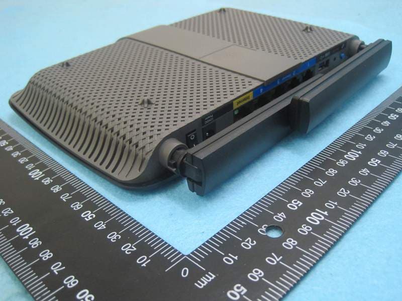
Click to zoom
Application Details
- Equipment Class
- NII - Unlicensed National Information Infrastructure TX
- Date of Grant
- Mar 18, 2014
- Application Purpose
- Original Equipment
- Date of Application
- Mar 18, 2014
- Equipment Note
- Linksys Smart Wi-Fi Router AC1200
- Frequency Range
- 5210.00000000 - 5210.00000000
- Company
- LINKSYS LLC
- Country
- United States
Documents & Files
Document Text
Text extracted from the exhibit documents filed with the FCC. Open a document above to read the original.
Users Manual
Product Overview EA6350 Top view Indicator light —Stays on steadily while power is connected and following a successful Wi-Fi Protected Setup connection. Flashes or pulses slowly during bootup, during firmware upgrades, and during a Wi - Fi Protected Setup connection. Flashes quickly when there is a Wi - Fi Protected Setup error. Back view Adjustable Antenna ports— The included 2 adjustable external antennas should be connected to the router before powering it on. Twist the antenna connector clockwise onto the port on the router. NOTE For best performance, position the side antennas at a 30 ̊ angle as shown in the picture on the left. Wi-Fi Protected Setup ™ button — Press to easily configure wireless security on Wi-Fi Protected Setup-enabled network devices. USB port —Connect and share a USB drive or a USB printer. Ethernet ports —Connect Ethernet cables to the blue gigabit (10/100/1000) ports and to wired Ethernet network devices. NOTE For best performance, use CAT5E or higher rated cables on the Ethernet ports. Internet port —Connect an Ethernet cable to this yellow port and to your modem. Reset button —Press and hold for 10 seconds (until the port lights flash at the same time) to reset the router to its factory defaults. You can also restore the defaults using Linksys Smart Wi-Fi. Power port —Connect the included AC power adapter. Power button —Press | (on) to turn on the router. Setting Up Your EA-Series Router Where to find more help Linksys.com/support (documentation, downloads, FAQs, technical support, live chat, forums) Linksys Smart Wi-Fi help (connect to Linksys Smart Wi-Fi , then click Help at the top of the screen) How to install your router To install your router: If replacing an existing router, disconnect it. Power on your new router. Connect the Internet cable from your modem to the yellow Internet port on your router. Wait until the power light on the front of the router is solid. Connect to the secure wireless name shown in the Quick Start Guide that came with your router. (You can change the network name and password later during router setup.) If you need help connecting to the network, refer to your device documentation CD. Note : You will not have Internet access until router setup is complete. Open a web browser and follow the instructions to complete your router’s setup. If instructions do not appear in the web browser, enter linksyssmartwifi.com in the browser’s address bar. At the end of setup, follow the on-screen instructions to set up your Linksys Smart Wi-Fi account. Use Linksys Smart Wi-Fi to easily manage your router’s settings, such as: Change your router’s name and password Set up guest access Configure parental controls Connect devices to your network Test your Internet connection speed NOTE: As part of Linksys Smart Wi-Fi account setup, you will be sent a verification e-mail. Make sure that you open the e-mail from Linksys and click the provided link. How to connect to Linksys Smart Wi-Fi You can use Linksys Smart Wi-Fi to configure your router from any computer that has an Internet connection. To open Linksys Smart Wi-Fi: Click the Linksys Smart Wi-Fi icon on your desktop. - OR - Open a web browser and go to www.linksyssmartwifi.com . Enter the e-mail address and password you set up earlierand click Log in . How to change router settings Use Linksys Smart Wi-Fi to change settings on your router and set up special features such as parental controls and guest access. NOTE: For additional help on any menu, click Help at the top of the screen. To change router settings: Open Linksys Smart Wi-Fi and log in to your account. In the menu on the left, click an option: Device List lets you display and manage all network devices connected to your router. You can view devices on your main network and your guest network, disconnect the devices, or display information about each device. Guest Access lets you configure a network so guests can access the Internet, but not all of your network resources. Parental Controls let you block web sites and set Internet access times. Media Prioritization lets you set which devices and applications have top priority for your network traffic. Speed Test lets you test your network’s Internet connection speed. USB Storage lets you access an attached USB drive (not included) and set up file sharing, a media server, and FTP access. (Available only on routers with USB ports.) Connectivity lets you configure basic and advanced network settings. Troubleshooting lets you diagnose problems with your router and check the status of the network. Wireless lets you configure your router’s wireless network. You can change the security mode, password, MAC filtering, and connect devices using Wi-Fi Protected Setup™. Security lets you configure your router’s wireless security. You can set up the firewall, VPN settings, and make custom settings for applications and games. Troubleshooting This chapter can help you solve common setup issues and connect to the Internet. You can find more help from our award-winning customer support at linksys.com/support. Your router was not successfully set up If Linksys Smart Wi-Fi did not complete the setup, you can try the following: Press and hold the Reset button on your router with a paperclip or pin until the LED starts flashing (about 10 seconds), then install the router again. Your router’s appearance may vary Temporarily disable your computer’s firewall (see the security software’s instructions for help), and install the router again. If you have another computer, use that computer to install the router again. Windows XP Service Pack update On Windows XP computers, Linksys Smart Wi-Fi requires Service Pack 3. If the currently installed Service Pack is older than version 3, you need to download and install Service Pack 3. TIP To temporarily connect to the Internet and download the required Service Pack, you can use the included Ethernet cable to connect your computer directly to your modem. To install Ser…
Text truncated - open the document above for the full version.
External Photos
Report No.: 421018 SPORTON International Inc. PAGE NUMBER : A1 OF A7 TEL : 886-3-327-3456 ISSUED DATE : Mar. 18, 2014 FAX : 886-3-327-0973 APPENDIX A. Photographs of EUT Report No.: 421018 SPORTON International Inc. PAGE NUMBER : A2 OF A7 TEL : 886-3-327-3456 ISSUED DATE : Mar. 18, 2014 FAX : 886-3-327-0973 Report No.: 421018 SPORTON International Inc. PAGE NUMBER : A3 OF A7 TEL : 886-3-327-3456 ISSUED DATE : Mar. 18, 2014 FAX : 886-3-327-0973 Report No.: 421018 SPORTON International Inc. PAGE NUMBER : A4 OF A7 TEL : 886-3-327-3456 ISSUED DATE : Mar. 18, 2014 FAX : 886-3-327-0973 Adapter 1 (Fixed plug) Brand: APD Model: WA-24E12FU Report No.: 421018 SPORTON International Inc. PAGE NUMBER : A5 OF A7 TEL : 886-3-327-3456 ISSUED DATE : Mar. 18, 2014 FAX : 886-3-327-0973 Adapter 2 (Interchangeable plug) Brand: APD Model: WA-24E12 Report No.: 421018 SPORTON International Inc. PAGE NUMBER : A6 OF A7 TEL : 886-3-327-3456 ISSUED DATE : Mar. 18, 2014 FAX : 886-3-327-0973 Report No.: 421018 SPORTON International Inc. PAGE NUMBER : A7 OF A7 TEL : 886-3-327-3456 ISSUED DATE : Mar. 18, 2014 FAX : 886-3-327-0973 Plug (Only for Adapter 2)
ID Label/Location Info
6 & ARTWORK_WG9116FAC22 1-88 01/27/2014 R01 Bel_Chan EA6350 EA6350 01/23/2014 R01 64.80 mm 20.00 mm & 3.00 mm 0.99 mm 18.00 mm 8.75 mm 7.53 mm 7.53 mm 2.86 mm 5 5 Bel_Chan ARTWORK_WG9116FAC22 1-88 5 5 5 5
Internal Photos
Report No.: 421018 SPORTON International Inc. PAGE NUMBER : A1 OF A10 TEL : 886-3-327-3456 ISSUED DATE : Mar. 18, 2014 FAX : 886-3-327-0973 APPENDIX A. Photographs of EUT Report No.: 421018 SPORTON International Inc. PAGE NUMBER : A2 OF A10 TEL : 886-3-327-3456 ISSUED DATE : Mar. 18, 2014 FAX : 886-3-327-0973 Report No.: 421018 SPORTON International Inc. PAGE NUMBER : A3 OF A10 TEL : 886-3-327-3456 ISSUED DATE : Mar. 18, 2014 FAX : 886-3-327-0973 Report No.: 421018 SPORTON International Inc. PAGE NUMBER : A4 OF A10 TEL : 886-3-327-3456 ISSUED DATE : Mar. 18, 2014 FAX : 886-3-327-0973 Report No.: 421018 SPORTON International Inc. PAGE NUMBER : A5 OF A10 TEL : 886-3-327-3456 ISSUED DATE : Mar. 18, 2014 FAX : 886-3-327-0973 Report No.: 421018 SPORTON International Inc. PAGE NUMBER : A6 OF A10 TEL : 886-3-327-3456 ISSUED DATE : Mar. 18, 2014 FAX : 886-3-327-0973 Report No.: 421018 SPORTON International Inc. PAGE NUMBER : A7 OF A10 TEL : 886-3-327-3456 ISSUED DATE : Mar. 18, 2014 FAX : 886-3-327-0973 Report No.: 421018 SPORTON International Inc. PAGE NUMBER : A8 OF A10 TEL : 886-3-327-3456 ISSUED DATE : Mar. 18, 2014 FAX : 886-3-327-0973 Report No.: 421018 SPORTON International Inc. PAGE NUMBER : A9 OF A10 TEL : 886-3-327-3456 ISSUED DATE : Mar. 18, 2014 FAX : 886-3-327-0973 Report No.: 421018 SPORTON International Inc. PAGE NUMBER : A10 OF A10 TEL : 886-3-327-3456 ISSUED DATE : Mar. 18, 2014 FAX : 886-3-327-0973
RF Exposure Info
Report No.: FR421018 FCC ID: Q87-EA6350 Page No. : C1 of C3 Appendix C. Maximum Permissible Exposure Report No.: FR421018 FCC ID: Q87-EA6350 Page No. : C2 of C3 1. Maximum Permissible Exposure 1.1. Applicable Standard Systems operating under the provisions of this section shall be operated in a manner that ensures that the public is not exposed to radio frequency energy levels in excess limit for maximum permissible exposure. In accordance with 47 CFR FCC Part 2 Subpart J, section 2.1091 this device has been defined as a mobile device whereby a distance of 0.2 m normally can be maintained between the user and the device. (A) Limits for Occupational / Controlled Exposure Frequency Range (MHz) Electric Field Strength (E) (V/m) Magnetic Field Strength (H) (A/m) Power Density (S) (mW/ cm²) Averaging Time |E|²,|H|² or S (minutes) 0.3-3.0 614 1.63 (100)* 6 3.0-30 1842 / f 4.89 / f (900 / f)* 6 30-300 61.4 0.163 1.0 6 300-1500 F/300 6 1500-100,000 5 6 (B) Limits for General Population / Uncontrolled Exposure Frequency Range (MHz) Electric Field Strength (E) (V/m) Magnetic Field Strength (H) (A/m) Power Density (S) (mW/ cm²) Averaging Time |E|²,|H|² or S (minutes) 0.3-1.34 614 1.63 (100)* 30 1.34-30 824/f 2.19/f (180/f)* 30 30-300 27.5 0.073 0.2 30 300-1500 F/1500 30 1500-100,000 1.0 30 Note: f = frequency in MHz ; *Plane-wave equivalent power density 1.2. MPE Calculation Method E (V/m) = d GP30 Power Density: Pd (W/m²) = 377 2 E E = Electric field (V/m) P = Average RF output power (W) G = EUT Antenna numeric gain (numeric) d = Separation distance between radiator and human body (m) The formula can be changed to Pd = 2 377 30 d GP From the EUT RF output power, the minimum mobile separation distance, d=0.2m, as well as the gain of the used antenna, the RF power density can be obtained. Report No.: FR421018 FCC ID: Q87-EA6350 Page No. : C3 of C3 1.3. Calculated Result and Limit For 5GHz UNII Band: Antenna Type : Dipole Antenna Conducted Power for IEEE 802.11ac VHT40: 16.50 dBm Antenna Gain (dBi) Antenna Gain (numeric) Average Output Power (dBm) Average Output Power (mW) Power Density (S) (mW/cm²) Limit of Power Density (S) (mW/cm²) Test Result 4.10 2.5704 16.4959 44.6259 0.022832 1 Complies For 5GHz ISM Band: Antenna Type : Dipole Antenna Conducted Power for IEEE 802.11ac VHT40: 29.27 dBm Antenna Gain (dBi) Antenna Gain (numeric) Average Output Power (dBm) Average Output Power (mW) Power Density (S) (mW/cm²) Limit of Power Density (S) (mW/cm²) Test Result 4.10 2.5704 29.2674 844.7725 0.432205 1 Complies For 2.4GHz Band: Antenna Type : Dipole Antenna Conducted Power for IEEE 802.11g: 24.51 dBm Antenna Gain (dBi) Antenna Gain (numeric) Average Output Power (dBm) Average Output Power (mW) Power Density (S) (mW/cm²) Limit of Power Density (S) (mW/cm²) Test Result 3.10 2.0417 24.5140 282.7484 0.114908 1 Complies CONCULSION: Both of the WLAN 2.4GHz Band and WLAN 5GHz Band can transmit simultaneously, the formula of calculatedthe MPE is: CPD1 / LPD1 + CPD2 / LPD2 + ......etc. < 1 CPD = Calculation power density LPD = Limit of power density Therefore, the worst-case situation is 0.114908 / 1 + 0.432205 / 1 = 0.547113, which is less than “1”. This confirmed that the device comply with FCC 1.1310 MPE limit.
Test Report
SPORTON International Inc. No. 52, Hwa Ya 1st Rd., Hwa Ya Technology Park, Kwei-Shan Hsiang, Tao Yuan Hsien, Taiwan, R.O.C. Ph: 886-3-327-3456 / FAX: 886-3-327-0973 / www.sporton.com.tw Report Format Version: 01 FCC RADIO TEST REPORT Applicant’s company Linksys LLC Applicant Address 131 Theory Drive, Irvine, CA 92617, USA FCC ID Q87-EA6350 Product Name Linksys Smart Wi-Fi Router AC1200 Brand Name Linksys Model No. EA6350 Test Rule Part(s) 47 CFR FCC Part 15 Subpart E § 15.407 Test Freq. Range 5150 ~ 5250MHz Received Date Feb. 10, 2014 Final Test Date Mar. 12, 2014 Submission Type Original Equipment Statement Test result included is for the IEEE 802.11n and IEEE 802.11a/ac (5150 ~ 5250MHz) of the product. The test result in this report refers exclusively to the presented test model / sample. Without written approval of SPORTON International Inc., the test report shall not be reproduced except in full. The measurements and test results shown in this test report were made in accordance with the procedures and found in compliance with the limit given in ANSI C63.10-2009, 47 CFR FCC Part 15 Subpart E, KDB 789033 D01 v01r03, KDB 662911 D01 v02r01, KDB644545 D01v01r02. The test equipment used to perform the test is calibrated and traceable to NML/ROC. Report No.: FR421018AB Report Format Version: 01 Page No. : i of ii FCC ID: Q87-EA6350 Issued Date : Mar. 18, 2014 Table of Contents 1. CERTIFICATE OF COMPLIANCE ......................................................................................................................... 1 2. SUMMARY OF THE TEST RESULT .......................................................................................................................... 2 3. GENERAL INFORMATION .................................................................................................................................. 3 3.1. Product Details....................................................................................................................................................................................3 3.2. Accessories .........................................................................................................................................................................................5 3.3. Table for Filed Antenna.......................................................................................................................................................................6 3.4. Table for Carrier Frequencies .............................................................................................................................................................8 3.5. Table for Test Modes ...........................................................................................................................................................................9 3.6. Table for Testing Locations................................................................................................................................................................10 3.7. Table for Supporting Units .................................................................................................................................................................11 3.8. Table for Parameters of Test Software Setting ...................................................................................................................................12 3.9. EUT Operation during Test .................................................................................................................................................................12 3.10. Duty Cycle ........................................................................................................................................................................................13 3.11. Test Configurations ...........................................................................................................................................................................16 4. TEST RESULT ................................................................................................................................................... 19 4.1. AC Power Line Conducted Emissions Measurement.........................................................................................................................19 4.2. 26dB Bandwidth and 99% Occupied Bandwidth Measurement......................................................................................................25 4.3. Maximum Conducted Output Power Measurement .........................................................................................................................34 4.4. Power Spectral Density Measurement ..............................................................................................................................................37 4.5. Peak Excursion Measurement ...........................................................................................................................................................44 4.6. Radiated Emissions Measurement ....................................................................................................................................................50 4.7. Band Edge Emissions Measurement .................................................................................................................................................71 4.8. Frequency Stability Measurement ....................................................................................................................................................78 4.9. Antenna Requirements .....................................................................................................................................................................80 5. LIST OF MEASURING EQUIPMENTS ................................................................................................................... 81 6. MEASUREME…
Text truncated - open the document above for the full version.
Test Report
Report No.: FR421018 FCC ID: Q87-EA6350 Page No. : D1 of D3 Appendix D. Radiated Emission Co-location Report Report No.: FR421018 FCC ID: Q87-EA6350 Page No. : D2 of D3 1. Results of Radiated Emissions for Co-located Temperature 25°C Humidity 50% Test Engineer Nick Peng Configurations 2.4G + 5G Horizontal Report No.: FR421018 FCC ID: Q87-EA6350 Page No. : D3 of D3 Vertial
Test Setup Photos
Report No.: FR421018 FCC ID: Q87-EA6350 Page No. : B1 of B5 Appendix B. Test Photos Report No.: FR421018 FCC ID: Q87-EA6350 Page No. : B2 of B5 1. Photographs of Conducted Emissions Test Configuration FRONT VIEW REAR VIEW Report No.: FR421018 FCC ID: Q87-EA6350 Page No. : B3 of B5 2. Photographs of Radiated Emissions Test Configuration Test Configuration: 9kHz ~30MHz FRONT VIEW REAR VIEW Report No.: FR421018 FCC ID: Q87-EA6350 Page No. : B4 of B5 Test Configuration: 30MHz~1GHz FRONT VIEW REAR VIEW Report No.: FR421018 FCC ID: Q87-EA6350 Page No. : B5 of B5 Test Configuration: Above 1GHz FRONT VIEW REAR VIEW
Contact Information
Applicant
Po-Wen Cheng(Regulatory Compliance Manager)
Test Firm
Sporton International Inc.Alex Chen
Technical Specifications
| # | Rule Parts | Frequency Range | Power Output |
|---|---|---|---|
| 3 | 15E | 5.21 GHz - 5.21 GHz | 31.70 mW |
Other Applications from LINKSYS LLC

Q87-WDS060
Aug 11, 2020WiFi Smart Light Switch with Dimmer
Equipment Class
DTS - Digital Transmission System
Q87-03564
Jun 28, 2020Linksys Tri-Band Wireless-AC Router
Equipment Class
NII - Unlicensed National Information Infrastructure TX
Q87-03566
Jun 23, 2020Linksys Tri-Band Wireless-AC Router
Equipment Class
NII - Unlicensed National Information Infrastructure TX
Q87-03530
Apr 29, 2020Linksys MAX-STREAM AC1900+ WiFi Range Extender
Equipment Class
NII - Unlicensed National Information Infrastructure TX
Q87-08151
Mar 30, 2020Linksys Dual-Band 802.11ax Wireless Router
Equipment Class
DTS - Digital Transmission System