Q87-HGA5T-4Wireless Network Access Point
LINKSYS LLC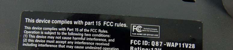
Click to zoom
Application Details
- Equipment Class
- DTS - Digital Transmission System
- Date of Grant
- Nov 11, 2004
- Application Purpose
- Original Equipment
- Date of Application
- Nov 11, 2004
- Equipment Note
- Wireless Network Access Point
- Frequency Range
- 2412.00000000 - 2452.00000000
- Company
- LINKSYS LLC
- Country
- United States
Documents & Files
Document Text
Text extracted from the exhibit documents filed with the FCC. Open a document above to read the original.
Users Manual
Wireless-B Access Point Use this guide to install: WAP11 User Guide COPYRIGHT & TRADEMARKS Specifications are subject to change without notice. Linksys is a registered trademark ortrademark of Cisco Systems, Inc. and/or its affiliates in the U.S. and certain other countries.Copyright © 2003 Cisco Systems, Inc. All rights reserved. Other brands and productnames are trademarks or registered trademarks of their respective holders. LIMITED WARRANTY Linksys warrants to the original end user purchaser (“You”) that, for a period of one year,(the “Warranty Period”) Your Linksys product will be free of defects in materials and work-manship under normal use. Your exclusive remedy and Linksys’s entire liability under thiswarranty will be for Linksys at its option to repair or replace the product or refund Your pur-chase price less any rebates.If the product proves defective during the Warranty Period call Linksys Technical Supportin order to obtain a Return Authorization Number. BE SURE TO HAVE YOUR PROOF OFPURCHASE ON HAND WHEN CALLING. When returning a product, mark the ReturnAuthorization Number clearly on the outside of the package and include a copy of youroriginal proof of purchase. RETURN REQUESTS CANNOT BE PROCESSED WITHOUTPROOF OF PURCHASE. You are responsible for shipping defective products to Linksys.Linksys pays for UPS Ground shipping from Linksys back to You only. Customers locatedoutside of the United States of America and Canada are responsible for all shipping andhandling charges. ALL IMPLIED WARRANTIES AND CONDITIONS OF MERCHANTABILITY OR FITNESS FORA PARTICULAR PURPOSE ARE LIMITED TO THE DURATION OF THE WARRANTY PERI-OD. ALL OTHER EXPRESS OR IMPLIED CONDITIONS, REPRESENTATIONS AND WAR-RANTIES, INCLUDING ANY IMPLIED WARRANTY OF NON-INFRINGEMENT, ARE DIS-CLAIMED. Some jurisdictions do not allow limitations on how long an implied warranty lasts,so the above limitation may not apply to You. This warranty gives You specific legal rights,and You may also have other rights which vary by jurisdiction.TO THE EXTENT NOT PROHIBITED BY LAW, IN NO EVENT WILL LINKSYS BE LIABLEFOR ANY LOST DATA, REVENUE OR PROFIT, OR FOR SPECIAL, INDIRECT, CONSE-QUENTIAL, INCIDENTAL OR PUNITIVE DAMAGES, HOWEVER CAUSED REGARDLESSOF THE THEORY OF LIABILITY, ARISING OUT OF OR RELATED TO THE USE OF ORINABILITY TO USE THE PRODUCT, EVEN IF LINKSYS HAS BEEN ADVISED OF THE POS-SIBILITY OF SUCH DAMAGES. IN NO EVENT WILL LINKSYS' LIABILITY EXCEED THEAMOUNT PAID BY YOU FOR THE PRODUCT. The foregoing limitations will apply even if any warranty or remedy provided under thisSection fails of its essential purpose. Some jurisdictions do not allow the exclusion or limi-tation of incidental or consequential damages, so the above limitation or exclusion may notapply to You.Please direct all inquiries to: Linksys, P.O. Box 18558, Irvine, CA 92623. FCC STATEMENTThis product has been tested and complies with the specifications for a Class B digitaldevice, pursuant to Part 15 of the FCC Rules. These limits are designed to provide rea-sonable protection against harmful interference in a residential installation. This equip-ment generates, uses, and can radiate radio frequency energy and, if not installed andused according to the instructions, may cause harmful interference to radio communi-cations. However, there is no guarantee that interference will not occur in a particularinstallation. If this equipment does cause harmful interference to radio or televisionreception, which is found by turning the equipment off and on, the user is encouraged totry to correct the interference by one or more of the following measures:• Reorient or relocate the receiving antenna• Increase the separation between the equipment or devices• Connect the equipment to an outlet other than the receiver’s• Consult a dealer or an experienced radio/TV technician for assistanceFCC Radiation Exposure StatementThis equipment complies with FCC radiation exposure limits set forth for an uncontrolledenvironment. This equipment should be installed and operated with minimum distance20cm between the radiator and your body.INDUSTRY CANADA (CANADA)This Class B digital apparatus complies with Canadian ICES-003.Cet appareil numérique de la classe B est conforme à la norme NMB-003 du Canada.The use of this device in a system operating either partially or completely outdoors mayrequire the user to obtain a license for the system according to the Canadian regulations.EC DECLARATION OF CONFORMITY (EUROPE)Linksys Group declares that the Wireless-B Access Point conforms to the specificationslisted below, following the provisions of the European R&TTE directive 1999/5/EC: For 11Mbps, 2.4 GHz devices with 100 mW radios, the following standards were applied: • EN 301 489-1, 301 489-17 General EMC requirements for Radio equipment. • EN 609 50 Safety • ETS 300-328-2 Technical requirements for Radio equipment. Caution: This equipment is intended to be used in all EU and EFTA countries. Outdooruse may be restricted to certain frequencies and/or may require a license for operation.Contact local Authority for procedure to follow.Note: Combinations of power levels and antennas resulting in a radiated power level ofabove 100 mW equivalent isotropic radiated power (EIRP) are considered as not com-pliant with the above mentioned directive and are not allowed for use within the Europeancommunity and countries that have adopted the European R&TTE directive 1999/5/EC. For more details on legal combinations of power levels and antennas, contact LinksysCorporate Compliance.• Linksys Group vakuuttaa täten että Wireless-B Access Point tyyppinen laite on direk- tiivin 1999/5/EY oleellisten vaatimusten ja sitä koskevien näiden direktiivien muidenehtojen mukainen. • Linksys Group déclare que la Wireless-B Access Point est conforme aux conditions essentielles et aux dispositions relatives à la directive 1999/5/EC. This device complies with Part 15 of the FCC Rules. Operation is subject to the following t…
Text truncated - open the document above for the full version.
Cover Letter(s)
Cisco-Linksys, LLC 121 Theory Drive Irvine, CA 92612 (USA) Phone: 949-823-3188 Fax: 949-823-3002 Date: October 20, 2004 FCC ID: Q87-HGA5T-4 Federal Communications Commission Authorization and Evaluation Division Confidentiality Request Pursuant to Sections 0.457 and 0.459 of the Commission’s Rules, the Applicant hereby requests confidential treatment of information accompanying this Application as outlined below: Schematics Block Diagram The above materials contain trade secrets and proprietary information not customarily released to the public. The public disclosure of these matters might be harmful to the Applicant and provide unjustified benefits to its competitors. The Applicant understands that pursuant to Rule 0.457, disclosure of this Application and all accompanying documentation will not be made before the date of the Grant for this application. Sincerely yours, __________________________________________ Jennifer Yu / Associate Engineer Cisco-Linksys, LLC Tel.: ( 949 ) 823-3188 Fax: ( 949 ) 823-3002 [email protected]
Cover Letter(s)
Cisco-Linksys, LLC 121 Theory Drive Irvine, CA 92612 (USA) Phone: 949-823-3188 Fax: 949-823-3002 Date: October 20, 2004 FEDERAL COMMUNICATIONS COMMISSION DECLARATION OF CONFORMITY (DoC) Cisco-Linksys, LLC declares that the equipment described in this document is within the requirements of the Code of Federal Regulations listed below: Product Name: Wireless Network Access Point Model Number: WAP11V28 This device complies with the limits for a Class B digital device pursuant to IEEE ANSI C63.4 and FCC Part 15 subpart B of the Rules and Regulations. The test result has been shown in the ADT test report with numbered FD931009L03 Operation is subject to the following two conditions: 1. This device may not cause harmful interference. 2. This device must accept any interference received, including interference that may cause undesired operation. The Part 15 radio device operates on a non-interference basis with other devices operation at this frequency. Any change or modification to the product not expressly approved by Linksys could void the user’s authority to operate the device. Jennifer Yu / Associate Engineer Cisco-Linksys, LLC Tel.: ( 949 ) 823-3188 Fax: ( 949 ) 823-3002 [email protected]
Cover Letter(s)
Cisco-Linksys, LLC 121 Theory Drive Irvine, CA 92612 (USA) Phone: 949-823-3188 Fax: 949-823-3002 Agency Authorization Letter Date: October 20, 2004 To whom it may concern: We, the undersigned, hereby authorize Advance Data Technology Corp. (ADT) of Taiwan to act on our behalf, as our agent, in the following matters related to the FCC approval of our products: report submittal, related correspondence, the signing of all documents relating to these matters, and any other lawful activity necessary to obtain such certification. Any act carried out by ADT within the scope of this authorization shall have the same effects as our own. This authorization shall expire six months from the original date. If you have any questions regarding the authorization, please don’t hesitate to contact us. Thank you! Sincerely yours, _________________________________________ Jennifer Yu / Associate Engineer Cisco-Linksys, LLC Tel.: ( 949 ) 823-3188 Fax: ( 949 ) 823-3002 [email protected]
External Photos
Page 1 CONSTRUCTION PHOTOS OF EUT Page 2 Page 3 Page 4 Page 5 Page 6 Page 7 Page 8
ID Label/Location Info
Access Point Wireless Network xxxxxxxxxxxx WAP11V28 Operation is subject to the following two conditions:(1) This device may not cause harmful interference, and(2) this device must accept any interference received, including interference that may cause undesired operation. FCC ID: Q87-HGA5T-4 Rating: 12V This device complies with Part 15 of the FCC Rules.
Internal Photos
Page 9 Page 10 Page 11 Page 12 Page 13 Page 14
Operational Description
FCC ID: Q87-HGA5T-4 Report No. RF931009L03 Operational Description The transmitter of the EUT is powered by AC adapter. The antenna type is Dipole antenna with revers TNC antenna connector. The other instruction, please have a look at the users manual. DSSS Information This device is Direct Sequence Spread Spectrum, the data is mixed by pseudorandom code which is an orthogonal code. The mixed data is digital modulated by BPSK and QPSK technique depends on the data rates. The CCK coding is applied for increasing the data rate, and also the processing gain will be increased. The bit rates are 1,2,5.5,11Mbps, the symbol rates are 1,1,1.375,1.375Mbps, the chip rates are always 11Mbps. So, the Chip/symbol is 11,11,8 and 8 respectively. Although is higher bit rate, the processing gain is lower than 10, but the CCK coding used in higher bit rate will provide 2.2dB coding gain.
RF Exposure Info
FCC ID: Q87-HGA5T-4 Report No: SA931009L03 1 RF EXPOSURE REPORT REPORT NO.: SA931009L03 MODEL NO.: WAP11V28 ACCORDING: FCC Guidelines for Human Exposure IEEE C95.1 APPLICANT: Cisco-Linksys, LLC ADDRESS: 121 Theory Drive Irvine, CA 92612, U.S.A. ISSUED BY: Advance Data Technology Corporation TEST LOCATION: No. 19, Hwa Ya 2 nd Rd., Wen Hwa Tsuen, Kwei Shan Hsiang, Taoyuan Hsien 333, Taiwan, R.O.C. FCC ID: Q87-HGA5T-4 Report No: SA931009L03 2 RF Exposure Measurement (Mobile Device) 1. Introduction In this document, we try to prove the safety of radiation harmfulness to the human body for our product. The limit for Maximum Permissible Exposure (MPE) specified in FCC 1.1310 is followed. The Gain of the antenna used in this product is measured in a Fully Anechoic Chamber (FAC) calibrated for antenna measurement in ADT, and also the maximum total power input to the antenna is measured. Through the Friis transmission formula and the maximum gain of the antenna, we can calculate the distance, away from the product, where the limit of MPE is reached. Although the Friis transmission formula is a far field assumption, the calculated result of that is an over-prediction for near field power density. We will take that as the worst case to specify the safety range. 2. RF Exposure Limit According to FCC 1.1310: The criteria listed in the following table shall be used to evaluate the environmental impact of human exposure to radio-frequency (RF) radiation as specified in 1.1307(b) LIMITS FOR MAXIMUM PERMISSIBLE EXPOSURE (MPE) Frequency Range (MHz) Electric Field Strength (V/m) Magnetic Field Strength (A/m) Power Density (mW/cm 2 ) Average Time (minutes) (A)Limits For Occupational / Control Exposures 300-1500......F/3006 1500-100,000......56 (B)Limits For General Population / Uncontrolled Exposure 300-1500......F/15006 1500-100,000......1.030 F = Frequency in MHz FCC ID: Q87-HGA5T-4 Report No: SA931009L03 3 3. Friis Formula Friis transmission formula : Pd = (Pout*G) / (4*pi*r 2 ) where Pd = power density in mW/cm 2 Pout = output power to antenna in mW G = gain of antenna in linear scale Pi = 3.1416 R = distance between observation point and center of the radiator in cm If we know the maximum Gain of the antenna and the total power input to the antenna, through the calculation, we will know the MPE value at distance 20cm. Ref. : David K. Cheng, Field and Wave Electromagnetics, Second Edition, Page 640, Eq. (11-133). 4 EUT Operating condition The software provided by Manufacturer enabled the EUT to transmit and receive data at lowest, middle and highest channel individually. 5. Classification This device is not fixed inside the host equipment, it is connected with host through wire. So it is easy to be re-located in the place where at least 20cm far away from the body of the user. Warning statement to the user for keeping at least 20cm or more separation distance with the antenna should be included in users manual. So, this device is classified as Mobile Device. FCC ID: Q87-HGA5T-4 Report No: SA931009L03 4 6 Test Results 6.1 Antenna Gain The maximum Gain measured in Fully Anechoic Chamber is 5dBi or 3.162 (numeric). 6.2 Output Power Into Antenna & RF Exposure Distance: For 2.4GHz band: Channel Channel Frequency (MHz) Output Power to Antenna (mW) Power Density (mW/cm 2 ) Limit of Power Density (mW/cm 2 ) 1241216.2180.0101.0 6243731.6230.0201.0 11246216.5960.0101.0
Test Report
FCC ID: Q87-HGA5T-4 Report No.: RF931009L031Issued: Oct. 22, 2004 FCC TEST REPORT REPORT NO.: RF931009L03 MODEL NO.: WAP11V28 RECEIVED: Oct. 09, 2004 TESTED: Oct. 12 ~ Oct. 15, 2004 APPLICANT: Cisco-Linksys, LLC ADDRESS: 121 Theory Drive Irvine, CA 92612, U.S.A. ISSUED BY: Advance Data Technology Corporation LAB ADDRESS:No. 47, 14th Ling, Chia Pau Tsuen, Lin Kou Hsiang 244, Taipei Hsien, Taiwan, R.O.C. TEST LOCATION: No. 19, Hwa Ya 2 nd Rd., Wen Hwa Tsuen, Kwei Shan Hsiang, Taoyuan Hsien 333, Taiwan, R.O.C. This test report consists of 54 pages in total. It may be duplicated completely for legal use with the approval of the applicant. It should not be reproduced except in full, without the written approval of our laboratory. The client should not use it to claim product endorsement by CNLA, A2LA or any government agencies. The test results in the report only apply to the tested sample. 0528 ILAC MRA No. 2177-01 FCC ID: Q87-HGA5T-4 Report No.: RF931009L032Issued: Oct. 22, 2004 Table of Contents 1CERTIFICATION.........................................................................................................4 2SUMMARY OF TEST RESULTS................................................................................5 2.1MEASUREMENT UNCERTAINTY..............................................................................6 3GENERAL INFORMATION.........................................................................................7 3.1GENERAL DESCRIPTION OF EUT...........................................................................7 3.2DESCRIPTION OF TEST MODES.............................................................................8 3.3GENERAL DESCRIPTION OF APPLIED STANDARDS............................................8 3.4DESCRIPTION OF SUPPORT UNITS.......................................................................9 3.5CONFIGURATION OF SYSTEM UNDER TEST.....................................................10 4TEST TYPES AND RESULTS...................................................................................11 4.1CONDUCTED EMISSION MEASUREMENT............................................................11 4.1.1LIMITS OF CONDUCTED EMISSION MEASUREMENT.........................................11 4.1.2TEST INSTRUMENTS...............................................................................................11 4.1.3TEST PROCEDURES..............................................................................................12 4.1.4DEVIATION FROM TEST STANDARD....................................................................12 4.1.5TEST SETUP............................................................................................................13 4.1.6EUT OPERATING CONDITIONS.............................................................................14 4.1.7TEST RESULTS........................................................................................................15 4.2RADIATED EMISSION MEASUREMENT................................................................21 4.2.1LIMITS OF RADIATED EMISSION MEASUREMENT.............................................21 4.2.2TEST INSTRUMENTS..............................................................................................22 4.2.3TEST PROCEDURES..............................................................................................23 4.2.4DEVIATION FROM TEST STANDARD....................................................................23 4.2.5TEST SETUP............................................................................................................24 4.2.6EUT OPERATING CONDITIONS.............................................................................24 4.2.7TEST RESULTS........................................................................................................25 4.36dB BANDWIDTH MEASUREMENT........................................................................30 4.3.1LIMITS OF 6dB BANDWIDTH MEASUREMENT.....................................................30 4.3.2TEST INSTRUMENTS..............................................................................................30 4.3.3TEST PROCEDURE.................................................................................................31 4.3.4DEVIATION FROM TEST STANDARD....................................................................31 4.3.5TEST SETUP............................................................................................................31 4.3.6EUT OPERATING CONDITIONS.............................................................................31 4.3.7TEST RESULTS........................................................................................................32 4.4MAXIMUM PEAK OUTPUT POWER.......................................................................36 4.4.1LIMITS OF MAXIMUM PEAK OUTPUT POWER MEASUREMENT.......................36 4.4.2TEST INSTRUMENTS..............................................................................................36 4.4.3TEST PROCEDURES..............................................................................................37 4.4.4DEVIATION FROM TEST STANDARD....................................................................37 FCC ID: Q87-HGA5T-4 Report No.: RF931009L033Issued: Oct. 22, 2004 4.4.5TEST SETUP............................................................................................................37 4.4.6EUT OPERATING CONDITIONS.............................................................................37 4.4.7TEST RESULTS........................................................................................................38 4.5POWER SPECTRAL DENSITY MEASUREMENT...................................................39 4.5.1LIMITS OF POWER SPECTRAL DENSITY MEASUREMENT................................39 4.5.2TEST INSTRUMENTS..............................................................................................39 4.5.3TEST PROCEDURE...........…
Text truncated - open the document above for the full version.
Test Setup Photos
FCC ID: Q87-HGA5T-4 Report No.: RF931009L0352Issued: Oct. 22, 2004 5 PHOTOGRAPHS OF THE TEST CONFIGURATION CONDUCTED EMISSION TEST FCC ID: Q87-HGA5T-4 Report No.: RF931009L0353Issued: Oct. 22, 2004 RADIATED EMISSION TEST
Contact Information
Applicant
Po-Wen Cheng(Regulatory Compliance Manager)
Technical Contact
Advance Data Technology CorporationEllis Wu
[email protected]+886 3 318 3232
N0. 19, Hwa Ya 2nd Rd · Taoyuan · Taiwan
Test Firm
Bureau Veritas CPS (H.K.) Ltd. Taoyuan BranchRichard Chen
Technical Specifications
| # | Rule Parts | Frequency Range | Power Output |
|---|---|---|---|
| 1 | 15C | 2.41 GHz - 2.45 GHz | 31.00 mW |
Other Applications from LINKSYS LLC

Q87-WDS060
Aug 11, 2020WiFi Smart Light Switch with Dimmer
Equipment Class
DTS - Digital Transmission System
Q87-03564
Jun 28, 2020Linksys Tri-Band Wireless-AC Router
Equipment Class
NII - Unlicensed National Information Infrastructure TX
Q87-03566
Jun 23, 2020Linksys Tri-Band Wireless-AC Router
Equipment Class
NII - Unlicensed National Information Infrastructure TX
Q87-03530
Apr 29, 2020Linksys MAX-STREAM AC1900+ WiFi Range Extender
Equipment Class
NII - Unlicensed National Information Infrastructure TX
Q87-08151
Mar 30, 2020Linksys Dual-Band 802.11ax Wireless Router
Equipment Class
DTS - Digital Transmission System