Q87-LAPAC1750POAC1750 Pro Dual Band Access Point
LINKSYS LLC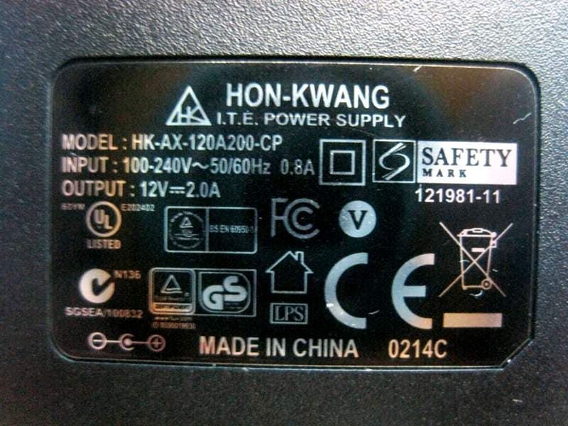
Click to zoom
Application Details
- Equipment Class
- DTS - Digital Transmission System
- Date of Grant
- May 05, 2014
- Application Purpose
- Original Equipment
- Date of Application
- May 05, 2014
- Equipment Note
- AC1750 Pro Dual Band Access Point
- Frequency Range
- 5775.00000000 - 5775.00000000
- Company
- LINKSYS LLC
- Country
- United States
Documents & Files
Document Text
Text extracted from the exhibit documents filed with the FCC. Open a document above to read the original.
Users Manual
L A PAC1750 P RO User Guide ii Table of Contents Linksys ii Section 1: Getting Started . . . . . . . . . . . . . . . . . . . . . . 1 Administrator’s Computer Requirements 1 Wireless Client Requirements 2 Online Help, Supported Browsers, and Limitations 2 Dynamic and Static IP Addressing on the AP 3 Installing the Access Point 3 Configuring the Ethernet Settings 5 Configuring IEEE 802 1X Authentication 6 Configuring Security on the Wireless Access Point 6 Section 2: Viewing Access Point System Status . . . . . . . . 7 System Summary 7 Network Interfaces 8 Radio Statistics 10 Workgroup Bridge 13 Associated Client 13 TSPEC Client Associations 15 TSPEC Status and Statistics 16 TSPEC AP Statistics 17 Email Alert Status 18 System Log 18 Section 3: Configuring the Access Point . . . . . . . . . . . . . 19 A dministration 19 LAN 29 Wireless 33 Security 63 QoS and Access Control 66 SNMP 81 Captive Portal 88 Cluster 88 Section 4: Maintenance of the Access Point . . . . . . . . .110 M aintenance 110 Diagnostics 114 Table of Contents 1 Section 1: Getting Started Linksys 1 Section 1: Getting Started The LAPAC1750PRO® Access Point provides continuous, high-speed access between wireless devices and Ethernet devices It is an advanced, standards- based solution for wireless networking in businesses of any size The access point (AP) enables wireless local area network (WLAN) deployment while providing state-of-the-art wireless networking features The access point can operate in one modes: Standalone Mode In Standalone Mode, the access point acts as an individual access point in the network, and you manage it by using the Administrator Web User Interface (UI) or SNMP T his document describes how to perform the setup, management, and maintenance of the access point in Standalone Mode B efore you power on a new access point, review the following sections to check required hardware and software components, client configurations, and compatibility issues Make sure you have everything you need for a successful launch and test of your new or extended wireless network This section contains the following topics: • Administrator’s Computer Requirements • W ireless Client Requirements • O nline Help, Supported Browsers, and Limitations • D ynamic and Static IP Addressing on the AP • I nstalling the Access Point • Configuring the Ethernet Settings • C onfiguring IEEE 802.1X Authentication • C onfiguring Security on the Wireless Access Point To manage the access point by using the Web interface, the AP needs an IP address If you use VLANs or IEEE 802 1 X Authentication (port security) on your network, you might need to configure additional settings on the AP before it can connect to the network note: The access point is not designed to function as a gateway to the Internet To connect your WLAN to other LANs or the Internet, you need a gateway device Administrator’s Computer Requirements The following table describes the minimum requirements for the administrator’s computer for configuration and administration of the access point through a Web-based user interface (UI) T able 1: Requirements for the Administrator’s Computer Required Software or Component Description ethernet Connection to the Access Point The computer used to configure the first access point must be connected to the access point by an Ethernet cable Wireless Connection to the network After initial configuration and launch of the first access point on your new wireless network, you can make subsequent configuration changes through the Administration Web pages using a wireless connection to the internal network For wireless connection to the access point, your administration device will need Wi-Fi capability similar to that of any wireless client: Portable or built-in Wi-Fi client adapter that supports one or more of the IEEE 802 11 modes in which you plan to run the access point 2 Section 1: Getting Started Linksys Web Browser and op erating System Configuration and administration of the access point is provided through a Web-based user interface hosted on the access point W e recommend using one of the following supported Web browsers to access the access point Administration Web pages: • Microsoft® Internet Explorer® version 9.x or 11 x (with up-to-date patch level for either major version) • Mozilla Firefox version 26.x • Google Chrome version 32.x • Safari version 5.x The administration Web browser must have JavaScript™ enabled to support the interactive features of the administration interface Se curity SettingsEnsure that security is disabled on the wireless client used to initially configure the access point Wireless Client Requirements The access point provides wireless access to any client with a properly configured Wi-Fi client adapter for the 802 11 mode in which the access point is running The access point supports multiple client operating systems Clients can be laptop or desktop computers, personal digital assistants (PDAs), or any other hand-held, portable or stationary device equipped with a Wi-Fi adapter and supporting drivers I n order to connect to the access point, wireless clients need the software and hardware described in the following table Table 2: Requirements for Wireless Clients Required ComponentDescription Wi-Fi Client AdapterPortable or built-in Wi-Fi client adapter that supports one or more of the IEEE 802 11 modes in which you plan to run the access point (IEEE 802 11a, 802 11b, 802 11g, 802 11n, and 802 11ac modes are supported ) Wireless Client Software Client software, such as Microsoft Windows Supplicant, configured to associate with the access point Client Security Settings Security should be disabled on the client used to do initial configuration of the access point I f the Security mode on the access point is set to anything other than plain text, wireless clients will need to set a profile to the authentication mode used by the access point and provide a valid username and password, certificate, or similar user i…
Text truncated - open the document above for the full version.
Users Manual
Regulatory Information Dual-Band Products Table of Contents i Table of Contents Wireless Regulatory Information FCC Statement . . . . . . . . . . . . . . . . . . . . . . . . . . . . . . . . . . . . . .1 Mexico Regulatory Statement . . . . . . . . . . . . . . . . . . . . . . . . . . . . . 1 EAC Mark of Conformity for Russia, Kazakhstan and Belarus . . . . . . . . . . 1 FCC Radiation Exposure Statement . . . . . . . . . . . . . . . . . . . . . . . . . 1 Safety Notices . . . . . . . . . . . . . . . . . . . . . . . . . . . . . . . . . . . . . . 1 Industry Canada Statement . . . . . . . . . . . . . . . . . . . . . . . . . . . . . . 7 Restrictions in the 5 GHz Band . . . . . . . . . . . . . . . . . . . . . . . . . . . . 8 Avis d’Industrie Canada . . . . . . . . . . . . . . . . . . . . . . . . . . . . . . . . . 8 Restrictions dans la bande 5 GHz . . . . . . . . . . . . . . . . . . . . . . . . . . . 8 Wireless Disclaimer . . . . . . . . . . . . . . . . . . . . . . . . . . . . . . . . . . . 8 Avis de non-responsabilité concernant les appareils sans fil . . . . . . . . . . . 8 Declaration of Conformity with Regard to EU Directive 1999/5/EC (R&TTE Directive) . . . . . . . . . . . . . . . . . . . . . . . . . . . . . . . . . . . . 9 Wireless Equipment (Wireless-AC/N/G/A/B Products) . . . . . . . . . . . . . . . . . . . . . . . . . . .10 National Restrictions . . . . . . . . . . . . . . . . . . . . . . . . . . . . . . . . . 10 Product Usage Restrictions . . . . . . . . . . . . . . . . . . . . . . . . . . . . . 11 Technical Documents on www .linksys .com . . . . . . . . . . . . . . . . . . . . . . . . . . . . . . . . . . . .11 WEEE Information User Information for Consumer Products Covered by EU Directive 2002/96/EC on Waste Electric and Electronic Equipment (WEEE) . . . . . . 12 1 Wireless Regulatory Information Wireless Regulatory Information FCC Statement This device complies with Part 15 of the FCC Rules . Operation is subject to the following two conditions: (1) This device may not cause harmful interference, and (2) this device must accept any interference received, including interference that may cause undesired operation . This product has been tested and complies with the specifications for a Class B digital device, pursuant to Part 15 of the FCC Rules . These limits are designed to provide reasonable protection against harmful interference in a residential installation . This equipment generates, uses, and can radiate radio frequency energy and, if not installed and used according to the instructions, may cause harmful interference to radio communications . However, there is no guarantee that interference will not occur in a particular installation . If this equipment does cause harmful interference to radio or television reception, which is found by turning the equipment off and on, the user is encouraged to try to correct the interference by one or more of the following measures: •Reorient or relocate the receiving antenna •Increase the separation between the equipment or devices •Connect the equipment to an outlet other than the receiver’s •Consult a dealer or an experienced radio/TV technician for assistance FCC Caution: Any changes or modifications not expressly approved by the party responsible for compliance could void the user’s authority to operate this equipment . IEEE 802 .11b or 802 .11g operation of this product in the USA is firmware-limited to channels 1 through 11 . The device for the band 5150-5250 MHz is only for indoor usage to reduce the potential for harmful interference to co-channel mobile satellite systems . Mexico Regulatory Statement La operación de este equipo está sujeta a las siguientes dos condiciones: (1) es posible que este equipo o dispositivo no cause interferencia perjudicial y (2) este equipo o dispositivo debe aceptar cualquier interferencia, incluyendo la que pueda causar su operación no deseada . EAC Mark of Conformity for Russia, Kazakhstan and Belarus FCC Radiation Exposure Statement This equipment complies with FCC radiation exposure limits set forth for an uncontrolled environment . This equipment should be installed and operated with minimum distance 20 cm between the radiator and your body . This device and it’s antennas(s) must not be co-located or operating in conjunction with any other antenna or transmitter except in accordance with FCC multi- transmitter product procedures . Safety Notices English WARNING: Do not use this product near water, for example, in a wet basement or near a swimming pool . WARNING: Avoid using this product during an electrical storm . There may be a remote risk of electric shock from lightning . WARNING: This product may contain chemicals, known to the State of California to cause cancer, and birth defects or other reproductive harm . Wash hands after handling . WARNING: To reduce the risk of fire, use only No .26 AWG or larger telecommunication line cord . WARNING: This equipment will be inoperable when main power fails . WARNING: The power adaptor is the equipment ́s disconnection device . The power outlet must be located nearby the equipment and its access must be easy . 2 Wireless Regulatory Information ]Arabic[العربية لا تستخدم هذا المنتج بالقرب من الماء، على تحذير: سبيل المثال، في طابق سفلي رطب أو بالقرب من .حمام سباحة تجنب استخدام المنتج أثناء العاصفة تحذير: الرعدية. قد يكون هناك خطر بعيد للتعرض لصدمة كهربائية بسبب البرق. لتقليل احتمال الحريق، لا تستخدم سوى :تحذير حسب مقياس الأسلاك 26كابل خط اتصالات رقم أو كابل أكبر.AWGالأمريكي سيكون الجهاز غير قابل للتشغيل في حالة :تحذير تعطل مصدر الطاقة. مهايئ الطاقة هو أداة الفصل في هذا الجهاز. :تحذير يجب وضع الجهاز بالقرب من منفذ الطاقة بحيث يسهل الوصول إليه. Български ]Bulgarian[ ПРЕДУПРЕЖДЕНИЕ: Не използвайте устройството в близост до вода, напр . във влажно мазе или до плувен басейн . ПРЕДУПРЕЖДЕНИЕ: Избягвайте да използвате това устройство по време на буря . Възможно е да съществува несъществен риск от електрически удар от светкавица . ПРЕДУПРЕЖДЕНИЕ: За да се намали рис…
Text truncated - open the document above for the full version.
External Photos
Report No.:431102 SPORTON International Inc. PAGE NUMBER : 1 OF 7 TEL : 886-3-327-3456 ISSUED DATE : May. 05, 2014 FAX : 886-3-327-0973 Photographs of EUT Report No.:431102 SPORTON International Inc. PAGE NUMBER : 2 OF 7 TEL : 886-3-327-3456 ISSUED DATE : May. 05, 2014 FAX : 886-3-327-0973 Report No.:431102 SPORTON International Inc. PAGE NUMBER : 3 OF 7 TEL : 886-3-327-3456 ISSUED DATE : May. 05, 2014 FAX : 886-3-327-0973 Adapter 1 (Fixed Plug) Model No.: HK-AJ-120A200-US Report No.:431102 SPORTON International Inc. PAGE NUMBER : 4 OF 7 TEL : 886-3-327-3456 ISSUED DATE : May. 05, 2014 FAX : 886-3-327-0973 Adapter 2 (Interchangeable plug) Model No.: HK-AX-120A200-CP Report No.:431102 SPORTON International Inc. PAGE NUMBER : 5 OF 7 TEL : 886-3-327-3456 ISSUED DATE : May. 05, 2014 FAX : 886-3-327-0973 Report No.:431102 SPORTON International Inc. PAGE NUMBER : 6 OF 7 TEL : 886-3-327-3456 ISSUED DATE : May. 05, 2014 FAX : 886-3-327-0973 Cradle FCC Plug (only for Adapter 2) Report No.:431102 SPORTON International Inc. PAGE NUMBER : 7 OF 7 TEL : 886-3-327-3456 ISSUED DATE : May. 05, 2014 FAX : 886-3-327-0973
ID Label/Location Info
LAPAC1750FP
Internal Photos
Report No.:431102 SPORTON International Inc. PAGE NUMBER : 1 OF 3 TEL : 886-3-327-3456 ISSUED DATE : May. 05, 2014 FAX : 886-3-327-0973 Photographs of EUT Report No.:431102 SPORTON International Inc. PAGE NUMBER : 2 OF 3 TEL : 886-3-327-3456 ISSUED DATE : May. 05, 2014 FAX : 886-3-327-0973 Report No.:431102 SPORTON International Inc. PAGE NUMBER : 3 OF 3 TEL : 886-3-327-3456 ISSUED DATE : May. 05, 2014 FAX : 886-3-327-0973
RF Exposure Info
Report No.: FR431102 FCC ID: Q87-LAPAC1750PO Page No. : B1 of B3 Appendix B. Maximum Permissible Exposure Report No.: FR431102 FCC ID: Q87-LAPAC1750PO Page No. : B2 of B3 1. Maximum Permissible Exposure 1.1. Applicable Standard Systems operating under the provisions of this section shall be operated in a manner that ensures that the public is not exposed to radio frequency energy levels in excess limit for maximum permissible exposure. In accordance with 47 CFR FCC Part 2 Subpart J, section 2.1091 this device has been defined as a mobile device whereby a distance of 0.25 m normally can be maintained between the user and the device. (A) Limits for Occupational / Controlled Exposure Frequency Range (MHz) Electric Field Strength (E) (V/m) Magnetic Field Strength (H) (A/m) Power Density (S) (mW/ cm²) Averaging Time |E|²,|H|² or S (minutes) 0.3-3.0 614 1.63 (100)* 6 3.0-30 1842 / f 4.89 / f (900 / f)* 6 30-300 61.4 0.163 1.0 6 300-1500 F/300 6 1500-100,000 5 6 (B) Limits for General Population / Uncontrolled Exposure Frequency Range (MHz) Electric Field Strength (E) (V/m) Magnetic Field Strength (H) (A/m) Power Density (S) (mW/ cm²) Averaging Time |E|²,|H|² or S (minutes) 0.3-1.34 614 1.63 (100)* 30 1.34-30 824/f 2.19/f (180/f)* 30 30-300 27.5 0.073 0.2 30 300-1500 F/1500 30 1500-100,000 1.0 30 Note: f = frequency in MHz ; *Plane-wave equivalent power density 1.2. MPE Calculation Method E (V/m) = d GP30 Power Density: Pd (W/m²) = 377 2 E E = Electric field (V/m) P = Average RF output power (W) G = EUT Antenna numeric gain (numeric) d = Separation distance between radiator and human body (m) The formula can be changed to Pd = 2 377 30 d GP From the EUT RF output power, the minimum mobile separation distance, d=0.25m, as well as the gain of the used antenna, the RF power density can be obtained. Report No.: FR431102 FCC ID: Q87-LAPAC1750PO Page No. : B3 of B3 1.3. Calculated Result and Limit For 5GHz UNII Band: Antenna Type : PIFA Antenna Conducted Power for IEEE 802.11ac VHT 40 : 14.81dBm Directional Gain (dBi) Antenna Gain (numeric) Average Output Power (dBm) Average Output Power (mW) Power Density (S) (mW/cm²) Limit of Power Density (S) (mW/cm²) Test Result 8.18 6.5766 14.8055 30.2377 0.025333 1 Complies Note: For 5GHz ISM Band: Antenna Type : PIFA Antenna Conducted Power for IEEE 802.11ac VHT 20: 26.33dBm Directional Gain (dBi) Antenna Gain (numeric) Average Output Power (dBm) Average Output Power (mW) Power Density (S) (mW/cm²) Limit of Power Density (S) (mW/cm²) Test Result 9.65 9.2278 26.3344 429.9704 0.505438 1 Complies Note: For 2.4GHz Band: Antenna Type : PIFA Antenna Conducted Power for IEEE 802.11n HT 20: 27.48 dBm Antenna Gain (dBi) Antenna Gain (numeric) Average Output Power (dBm) Average Output Power (mW) Power Density (S) (mW/cm²) Limit of Power Density (S) (mW/cm²) Test Result 4.40 2.7542 27.4768 559.3469 0.196251 1 Complies CONCULSION: Both of the WLAN 2.4GHz Band and WLAN 5GHz Band can transmit simultaneously, the formula of calculatedthe MPE is: CPD1 / LPD1 + CPD2 / LPD2 + ......etc. < 1 CPD = Calculation power density LPD = Limit of power density Therefore, the worst-case situation is 0.505438 / 1 + 0.196251 / 1 = 0.701689, which is less than “1”. This confirmed that the device comply with FCC 1.1310 MPE limit.
Test Report
SPORTON International Inc. No. 52, Hwa Ya 1st Rd., Hwa Ya Technology Park, Kwei-Shan Hsiang, Tao Yuan Hsien, Taiwan, R.O.C. Ph: 886-3-327-3456 / FAX: 886-3-327-0973 / www.sporton.com.tw Report Format Version: Rev. 01 FCC RADIO TEST REPORT Applicant’s company Linksys LLC Applicant Address 131 Theory Drive Irvine California 92617 United States FCC ID Q87-LAPAC1750PO Manufacturer’s company Linksys LLC Manufacturer Address 131 Theory Drive Irvine California 92617 United States Product Name AC1750 Pro Dual Band Access Point Brand Name Linksys Model No. LAPAC1750PRO Test Rule Part(s) 47 CFR FCC Part 15 Subpart C § 15.247 Test Freq. Range 2400 ~ 2483.5MHz / 5725 ~ 5850MHz Received Date Mar. 11, 2014 Final Test Date Apr. 23, 2014 Submission Type Original Equipment Statement Test result included is only for the IEEE 802.11n, IEEE 802.11b/g and IEEE 802.11a/ac of the product. The test result in this report refers exclusively to the presented test model / sample. Without written approval of SPORTON International Inc., the test report shall not be reproduced except in full. The measurements and test results shown in this test report were made in accordance with the procedures and found in compliance with the limit given in ANSI C63.10-2009, 47 CFR FCC Part 15 Subpart C, KDB 558074 D01 v03r01, KDB 662911 D01 v02r01, KDB644545 D01v01r02. The test equipment used to perform the test is calibrated and traceable to NML/ROC. Report No.: FR431102AA Report Format Version: Rev. 01 Page No. : i of ii FCC ID: Q87-LAPAC1750PO Issued Date : Apr. 29, 2014 Table of Contents 1. CERTIFICATE OF COMPLIANCE ......................................................................................................................... 1 2. SUMMARY OF THE TEST RESULT .......................................................................................................................... 2 3. GENERAL INFORMATION .................................................................................................................................. 3 3.1. Product Details....................................................................................................................................................................................3 3.2. Accessories .........................................................................................................................................................................................5 3.3. Table for Filed Antenna.......................................................................................................................................................................6 3.4. Table for Carrier Frequencies .............................................................................................................................................................7 3.5. Table for Test Modes ...........................................................................................................................................................................8 3.6. Table for Testing Locations................................................................................................................................................................10 3.7. Table for Supporting Units .................................................................................................................................................................11 3.8. Table for Parameters of Test Software Setting ...................................................................................................................................12 3.9. EUT Operation during Test .................................................................................................................................................................14 3.10. Duty Cycle ........................................................................................................................................................................................15 3.11. Test Configurations ...........................................................................................................................................................................21 4. TEST RESULT ................................................................................................................................................... 25 4.1. AC Power Line Conducted Emissions Measurement.........................................................................................................................25 4.2. Maximum Conducted Output Power Measurement .........................................................................................................................29 4.3. Power Spectral Density Measurement ..............................................................................................................................................33 4.4. 6dB Spectrum Bandwidth Measurement ..........................................................................................................................................56 4.5. Radiated Emissions Measurement ....................................................................................................................................................67 4.6. Emissions Measurement ..................................................................................................................................................................101 4.7. Antenna Requirements ...................................................................................................................................................................138 5. LIST OF MEASURING EQUIPMENTS ................................................................................................................. 139 6. MEASUREMENT UNCERTAINTY........................................................................................................................ 141 APPENDIX A. TEST PHOTOS ................…
Text truncated - open the document above for the full version.
Test Report
Report No.: FR431102 FCC ID: Q87-LAPAC1750PO Page No. : C1 of C3 Appendix C. Radiated Emission Co-location Report Report No.: FR431102 FCC ID: Q87-LAPAC1750PO Page No. : C2 of C3 1. Results of Radiated Emissions for Co-located Temperature 24°C Humidity 55% Test Engineer Serway Li Configurations 2.4G + 5G Horizontal Report No.: FR431102 FCC ID: Q87-LAPAC1750PO Page No. : C3 of C3 Vertial
Test Setup Photos
Report No.: FR431102 FCC ID: Q87-LAPAC1750PO Page No. : A1 of A5 Appendix A. Test Photos Report No.: FR431102 FCC ID: Q87-LAPAC1750PO Page No. : A2 of A5 1. Photographs of Conducted Emissions Test Configuration Test Mode: Mode 3 FRONT VIEW REAR VIEW Report No.: FR431102 FCC ID: Q87-LAPAC1750PO Page No. : A3 of A5 2. Photographs of Radiated Emissions Test Configuration Test Configuration: 9kHz ~30MHz / Test Mode: Mode 2 FRONT VIEW REAR VIEW Report No.: FR431102 FCC ID: Q87-LAPAC1750PO Page No. : A4 of A5 Test Configuration: 30MHz~1GHz Test Mode: Mode 2 FRONT VIEW REAR VIEW Report No.: FR431102 FCC ID: Q87-LAPAC1750PO Page No. : A5 of A5 Test Configuration: Above 1GHz Test Mode: Mode 2 FRONT VIEW REAR VIEW
Contact Information
Applicant
Po-Wen Cheng(Regulatory Compliance Manager)
Test Firm
Sporton International Inc.Alex Chen
Technical Specifications
| # | Rule Parts | Frequency Range | Power Output |
|---|---|---|---|
| 5 | 15C | 5.78 GHz - 5.78 GHz | 394.50 mW |
Other Applications from LINKSYS LLC

Q87-WDS060
Aug 11, 2020WiFi Smart Light Switch with Dimmer
Equipment Class
DTS - Digital Transmission System
Q87-03564
Jun 28, 2020Linksys Tri-Band Wireless-AC Router
Equipment Class
NII - Unlicensed National Information Infrastructure TX
Q87-03566
Jun 23, 2020Linksys Tri-Band Wireless-AC Router
Equipment Class
NII - Unlicensed National Information Infrastructure TX
Q87-03530
Apr 29, 2020Linksys MAX-STREAM AC1900+ WiFi Range Extender
Equipment Class
NII - Unlicensed National Information Infrastructure TX
Q87-08151
Mar 30, 2020Linksys Dual-Band 802.11ax Wireless Router
Equipment Class
DTS - Digital Transmission System