Q87-RE3000WV2Linksys Wi-Fi Single-Band Wireless-N Range Extender
LINKSYS LLC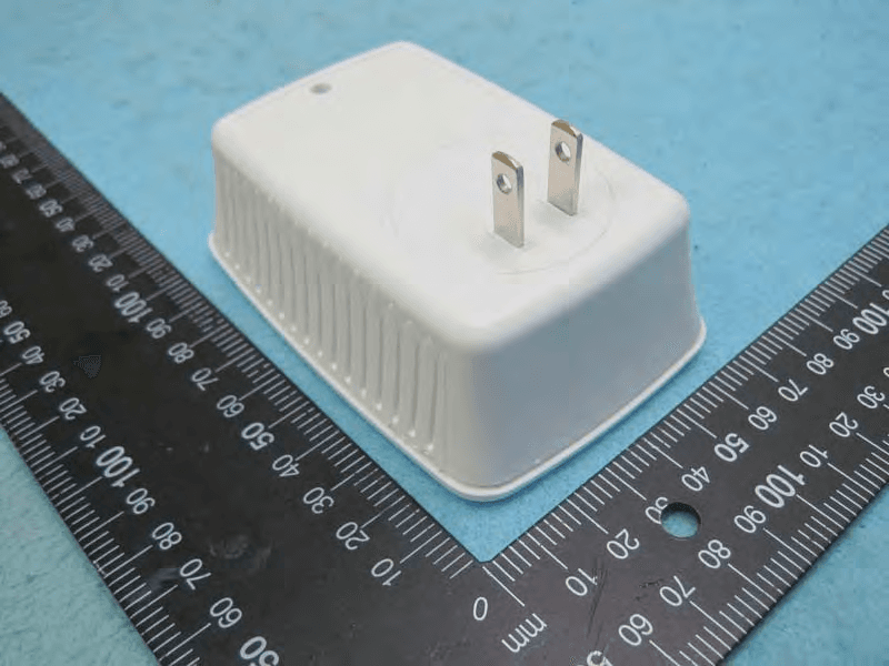
Click to zoom
Application Details
- Equipment Class
- DTS - Digital Transmission System
- Date of Grant
- Jan 18, 2015
- Application Purpose
- Original Equipment
- Date of Application
- Jan 15, 2015
- Equipment Note
- Linksys Wi-Fi Single-Band Wireless-N Range Extender
- Frequency Range
- 2422.00000000 - 2452.00000000
- Company
- LINKSYS LLC
- Country
- United States
Documents & Files
Document Text
Text extracted from the exhibit documents filed with the FCC. Open a document above to read the original.
Users Manual
User Guide RE3000W V2 Introduction This User Guide can help you connect the extender to your network and solve common setup issues. You can find more help from our award-winning, 24/7 customer support at Linksys.com/support. Contents Overview . . . . . . . . . . . . . . . . . . . . . . . . . . . . . . . . . . . . . . . . 1 How to install the range extender................ 2 How to access the browser-based utility .......... 5 Using Wi-Fi Protected Setup..................... 7 How to use Site Survey.......................... 9 Troubleshooting................................ 10 Specifications.................................. 13 Overview Front The light on the front of the range extender gives you information about power and Wi-Fi Protected Setup. Use Wi-Fi Protected Setup to automatically and securely connect compatible wireless devices such as wireless printers. Power Light Status/ description Blinking Green Powered on Resetting to factory defaults Upgrading its firmware Solid Green Ready to use Solid amber Weak connection with the router Fix: Unplug the extender, and move it closer to the router Blinking Orange Cannot establish a connection Other error Fix: Unplug the extender, plug it back in, wait two seconds, reconnect to your network Side Power Switch European versions only. Wi-Fi Protected Setup Button Use Wi-Fi Protected Setup to automatically and securely add compatible wireless devices to your network. Refer to Using Wi-Fi Protected Setup on page 7. Reset Press and hold for about five seconds to reset to factory defaults. You can also restore the defaults from the Administration > Factory Defaults screen in the extender’s browser- based utility. Bottom Ethernet (blue) Connect wired devices to your wireless network with Ethernet (network) cables. The green light turns on when an Ethernet device is connected and active on this port. The light blinks when the extender is sending or receiving data over the Ethernet port. How to install the range extender Before setup, unplug or disconnect any range extenders on the network. 1. Plug in the range extender midway between your router and the area without Wi-Fi. Be sure you have at least 50% of your router’s Wi-Fi signal at that point on the device you will use for setup. The setup software will help you find the best spot if you have trouble. 2. Wait for a solid light on the cover of the range extender. It could take up to two minutes. On a computer, phone or tablet, connect to the Wi-Fi network “Linksys Extender Setup.” Windows 7 and Windows 8 will ask you, “Do you want to set up your network?” Click the link, “Connect to network without setting it up.” 3. If setup doesn’t start automatically, open a browser to http://extender.linksys.com TIP You can also connect the range extender by using Wi-Fi Protected Setup. For more information, see “Using Wi-Fi Protected Setup” on page 7. How to access the browser-based utility After setting up the extender use the extender’s browser-based utility to change any settings. Windows XP: TIP To follow these instructions, enable UPnP: 1. Click Start, Control Panel, Add or Remove Program, then click Add/Remove Windows Components. 2. Select Network Services, then click Details. 3. Select UPnP User Interface, then click OK. 1. Open Windows Explorer. Click My Network Places on the left panel. 2. Look for the RE30 00W icon on the right panel. (You might be required to change the firewall settings to allow the display of networked computers. Refer to your operating system’s help for instructions.) 3. Double-click the RE30 00W icon. A web browser will open and prompt you to enter your User name and Password. 4. Leave the User name field blank, and enter the default password “admin.” 5. Click OK. Windows 8, Windows 7, or Vista: 1. Open Windows Explorer (File Explorer in Windows 8). Click Network. Look for the RE3000W icon on the right panel. (You might be required to change the firewall settings to allow the display of networked computers. Refer to your operating system’s help for instructions.) 2. Right-click the RE30 00W icon. Click Properties. Click on the address link in Device webpage. A web browser will open and prompt you to enter a User name and Password. 3. Leave the User name blank, and enter the default password “admin.” 4. Click OK. Mac OS X: 1. Open Safari. Click the book icon. Click Bonjour on the left panel. Look for the RE3000 W icon on the bottom right panel. 2. Double-click the RE3000W icon. 3. Leave the User name blank, and enter the default password “admin.” 4. Click OK. Using range extender settings Click Help on the right side of the screen for additional information on the screen’s options. Changes to settings will not be effective until you click Save Settings at the bottom of the screen. You also can click Cancel Changes to clear any changes. Using Wi-Fi Protected Setup Wi-Fi Protected Setup™ makes it easy to connect your extender to your network, and connect other devices to your network through the extender. Wi-Fi Protected Setup light activity WPS Light Status/ description Blinking Green When WPS connection is in process Solid Green When WPS connection is successful Blinking amber for two minutes When WPS cannot establish connection or encounters a problem Fix: wait a few seconds after LED stops blinking and try again Connecting the extender to an existing access point If your access point or router supports it, you can use Wi-Fi Protected Setup to connect the range extender to the access point or router. Choose from the setup methods below to connect the extender. NOTE If you have an access point or a router that does not support Wi-Fi Protected Setup, note the wireless settings, and then manually configure the extender. Connecting with the Wi-Fi Protected Setup Button Use this method if your router or access point has a Wi-Fi Protected Setup button. 1. Press the Wi-Fi Protected Setup button on the extender. 2. Click the Wi-Fi Protected Setup button on the ro…
Text truncated - open the document above for the full version.
Cover Letter(s)
LINKSYS LLC 121 Theory Drive, Irvine, CA 92617, USA Tel: 310-751-2816 / Fax: 310-751-5100 Confidential Letter Date: 2014/11/28 Federal Communications Commission Office of Engineering and Technology Equipment Authorization Division 7345 Oakland Mills Road Columbia, Maryland 21046 Subject: Confidentiality Request for FCC ID:Q87-RE3000WV2 Gentlemen: The form 731 and application have been electronically submitted and any attachments will be up loaded to your web site to be used in obtaining a grant of certification. Short-term Pursuant to DA 04-1705 of the Commission’s pubic notice, we request short-term confidential treatment for the following information until 180 days after the Grant Date of Equipment Authorization in order to ensure sensitive business information remains confidential until the actual marketing of the device: 1. External Photos 2. Internal Photos 3. Test Setup photos 4. User’s Manual Permanent LINKSYS LLC requests that the material in the following files be withheld from public disclosure in accordance with Section 0.457 of the Commission’s Rules, 47 C.F.R. 0.459, following grant of the application. 1. Block Diagram 2. Circuit Diagram 3. Operational Description Should you require any further information, please contact the undersigned. Thank you for your consideration in this matter. Sincerely, Applicant’s company name : LINKSYS LLC Applicant’s company address : 121 Theory Drive, Irvine, CA 92617, USA Signature : Name and Job Title : Daniel Wesey / Director of Global Requlatory Compliance E-Mail : [email protected] Tel. : 310-751-2816
Cover Letter(s)
LINKSYS LLC 121 Theory Drive, Irvine, CA 92617, USA Tel: 310-751-2816 / Fax: 310-751-5100 DoC Attestation Letter Date: 2014/11/28 We LINKSYS LLC, as the grantee of this project (FCC ID: Q87-RE3000WV2 / Brand Name: Linksys / Model No.: RE3000W V2), would like to declare that the composite portion categorized as computer peripheral has been authorized under the Declaration of Conformity procedures (Sporton report No.: FD4N2146, FCC Test Firm Registration No.: 187376). The final product shall consequently comply with the FCC rule applied for DoC Procedure. Regards, FCC Grantee contact person information. Applicant’s company name : LINKSYS LLC Applicant’s company address : 121 Theory Drive, Irvine, CA 92617, USA Signature : Name and Job Title : Daniel Wesey / Director of Global Requlatory Compliance E-Mail : [email protected] Tel. : 310-751-2816
Cover Letter(s)
LINKSYS LLC 121 Theory Drive, Irvine, CA 92617, USA Tel: 310-751-2816 / Fax: 310-751-5100 Power of Attorney Date: 2014/11/28 Dear Sir, I hereby have entrusted the following person to be a proxy regarding application for Type Certification. Sporton International Inc. Address : No.8, Lane 724, Bo-ai St., Jhubei City, HsinChu County 302, Taiwan, R.O.C. Name : Leo Huang Job Title : Manager e-mail : [email protected] I am therefore responsible for the contents of the application. Brand name and model type of the specified radio equipment: Linksys / RE3000W V2 FCC ID: Q87-RE3000WV2 Product name: Linksys Wi-Fi Single-Band Wireless-N Range Extender FCC Grantee contact person information. Applicant’s company name : LINKSYS LLC Applicant’s company address : 121 Theory Drive, Irvine, CA 92617, USA Signature : Name and Job Title : Daniel Wesey / Director of Global Requlatory Compliance E-Mail : [email protected] Tel. : 310-751-2816
External Photos
Report No.:4N2146 SPORTON International Inc. PAGE NUMBER : 1 OF 6 TEL : 886-3-327-3456 ISSUED DATE : Jan. 13, 2015 FAX : 886-3-327-0973 Photographs of EUT EUT 1 Report No.:4N2146 SPORTON International Inc. PAGE NUMBER : 2 OF 6 TEL : 886-3-327-3456 ISSUED DATE : Jan. 13, 2015 FAX : 886-3-327-0973 Report No.:4N2146 SPORTON International Inc. PAGE NUMBER : 3 OF 6 TEL : 886-3-327-3456 ISSUED DATE : Jan. 13, 2015 FAX : 886-3-327-0973 Report No.:4N2146 SPORTON International Inc. PAGE NUMBER : 4 OF 6 TEL : 886-3-327-3456 ISSUED DATE : Jan. 13, 2015 FAX : 886-3-327-0973 EUT 2 Report No.:4N2146 SPORTON International Inc. PAGE NUMBER : 5 OF 6 TEL : 886-3-327-3456 ISSUED DATE : Jan. 13, 2015 FAX : 886-3-327-0973 Report No.:4N2146 SPORTON International Inc. PAGE NUMBER : 6 OF 6 TEL : 886-3-327-3456 ISSUED DATE : Jan. 13, 2015 FAX : 886-3-327-0973
ID Label/Location Info
8830-21719
Internal Photos
Report No.:4N2146 SPORTON International Inc. PAGE NUMBER : 1 OF 22 TEL : 886-3-327-3456 ISSUED DATE : Jan. 13, 2015 FAX : 886-3-327-0973 Photographs of EUT EUT 1 Report No.:4N2146 SPORTON International Inc. PAGE NUMBER : 2 OF 22 TEL : 886-3-327-3456 ISSUED DATE : Jan. 13, 2015 FAX : 886-3-327-0973 Report No.:4N2146 SPORTON International Inc. PAGE NUMBER : 3 OF 22 TEL : 886-3-327-3456 ISSUED DATE : Jan. 13, 2015 FAX : 886-3-327-0973 Report No.:4N2146 SPORTON International Inc. PAGE NUMBER : 4 OF 22 TEL : 886-3-327-3456 ISSUED DATE : Jan. 13, 2015 FAX : 886-3-327-0973 Report No.:4N2146 SPORTON International Inc. PAGE NUMBER : 5 OF 22 TEL : 886-3-327-3456 ISSUED DATE : Jan. 13, 2015 FAX : 886-3-327-0973 Report No.:4N2146 SPORTON International Inc. PAGE NUMBER : 6 OF 22 TEL : 886-3-327-3456 ISSUED DATE : Jan. 13, 2015 FAX : 886-3-327-0973 Report No.:4N2146 SPORTON International Inc. PAGE NUMBER : 7 OF 22 TEL : 886-3-327-3456 ISSUED DATE : Jan. 13, 2015 FAX : 886-3-327-0973 Report No.:4N2146 SPORTON International Inc. PAGE NUMBER : 8 OF 22 TEL : 886-3-327-3456 ISSUED DATE : Jan. 13, 2015 FAX : 886-3-327-0973 Report No.:4N2146 SPORTON International Inc. PAGE NUMBER : 9 OF 22 TEL : 886-3-327-3456 ISSUED DATE : Jan. 13, 2015 FAX : 886-3-327-0973 Report No.:4N2146 SPORTON International Inc. PAGE NUMBER : 10 OF 22 TEL : 886-3-327-3456 ISSUED DATE : Jan. 13, 2015 FAX : 886-3-327-0973 Power source board Brand: HON-KWANG Report No.:4N2146 SPORTON International Inc. PAGE NUMBER : 11 OF 22 TEL : 886-3-327-3456 ISSUED DATE : Jan. 13, 2015 FAX : 886-3-327-0973 EUT 2 Report No.:4N2146 SPORTON International Inc. PAGE NUMBER : 12 OF 22 TEL : 886-3-327-3456 ISSUED DATE : Jan. 13, 2015 FAX : 886-3-327-0973 Report No.:4N2146 SPORTON International Inc. PAGE NUMBER : 13 OF 22 TEL : 886-3-327-3456 ISSUED DATE : Jan. 13, 2015 FAX : 886-3-327-0973 Report No.:4N2146 SPORTON International Inc. PAGE NUMBER : 14 OF 22 TEL : 886-3-327-3456 ISSUED DATE : Jan. 13, 2015 FAX : 886-3-327-0973 Report No.:4N2146 SPORTON International Inc. PAGE NUMBER : 15 OF 22 TEL : 886-3-327-3456 ISSUED DATE : Jan. 13, 2015 FAX : 886-3-327-0973 Report No.:4N2146 SPORTON International Inc. PAGE NUMBER : 16 OF 22 TEL : 886-3-327-3456 ISSUED DATE : Jan. 13, 2015 FAX : 886-3-327-0973 Report No.:4N2146 SPORTON International Inc. PAGE NUMBER : 17 OF 22 TEL : 886-3-327-3456 ISSUED DATE : Jan. 13, 2015 FAX : 886-3-327-0973 Report No.:4N2146 SPORTON International Inc. PAGE NUMBER : 18 OF 22 TEL : 886-3-327-3456 ISSUED DATE : Jan. 13, 2015 FAX : 886-3-327-0973 Report No.:4N2146 SPORTON International Inc. PAGE NUMBER : 19 OF 22 TEL : 886-3-327-3456 ISSUED DATE : Jan. 13, 2015 FAX : 886-3-327-0973 Report No.:4N2146 SPORTON International Inc. PAGE NUMBER : 20 OF 22 TEL : 886-3-327-3456 ISSUED DATE : Jan. 13, 2015 FAX : 886-3-327-0973 Report No.:4N2146 SPORTON International Inc. PAGE NUMBER : 21 OF 22 TEL : 886-3-327-3456 ISSUED DATE : Jan. 13, 2015 FAX : 886-3-327-0973 Power source board Brand: KUANTECH INCORPORATED COMPANY Report No.:4N2146 SPORTON International Inc. PAGE NUMBER : 22 OF 22 TEL : 886-3-327-3456 ISSUED DATE : Jan. 13, 2015 FAX : 886-3-327-0973
RF Exposure Info
Report No.: FR4N2146 FCC ID: Q87-RE3000WV2 Page No. : B1 of B3 Appendix B. Maximum Permissible Exposure Report No.: FR4N2146 FCC ID: Q87-RE3000WV2 Page No. : B2 of B3 1. Maximum Permissible Exposure 1.1. Applicable Standard Systems operating under the provisions of this section shall be operated in a manner that ensures that the public is not exposed to radio frequency energy levels in excess limit for maximum permissible exposure. In accordance with 47 CFR FCC Part 2 Subpart J, section 2.1091 this device has been defined as a mobile device whereby a distance of 0.2 m normally can be maintained between the user and the device. (A) Limits for Occupational / Controlled Exposure Frequency Range (MHz) Electric Field Strength (E) (V/m) Magnetic Field Strength (H) (A/m) Power Density (S) (mW/ cm²) Averaging Time |E|²,|H|² or S (minutes) 0.3-3.0 614 1.63 (100)* 6 3.0-30 1842 / f 4.89 / f (900 / f)* 6 30-300 61.4 0.163 1.0 6 300-1500 F/300 6 1500-100,000 5 6 (B) Limits for General Population / Uncontrolled Exposure Frequency Range (MHz) Electric Field Strength (E) (V/m) Magnetic Field Strength (H) (A/m) Power Density (S) (mW/ cm²) Averaging Time |E|²,|H|² or S (minutes) 0.3-1.34 614 1.63 (100)* 30 1.34-30 824/f 2.19/f (180/f)* 30 30-300 27.5 0.073 0.2 30 300-1500 F/1500 30 1500-100,000 1.0 30 Note: f = frequency in MHz ; *Plane-wave equivalent power density 1.2. MPE Calculation Method E (V/m) = d GP30 Power Density: Pd (W/m²) = 377 2 E E = Electric field (V/m) P = Average RF output power (W) G = EUT Antenna numeric gain (numeric) d = Separation distance between radiator and human body (m) The formula can be changed to Pd = 2 377 30 d GP From the EUT RF output power, the minimum mobile separation distance, d=0.2m, as well as the gain of the used antenna, the RF power density can be obtained. Report No.: FR4N2146 FCC ID: Q87-RE3000WV2 Page No. : B3 of B3 1.3. Calculated Result and Limit Antenna Type : PCB Antenna Conducted Power for IEEE 802.11g: 24.25 dBm The maximum combined Average Output Power Distance (m) Antenna Gain (dBi) Antenna Gain (numeric) (dBm) (mW) Power Density (S) (mW/cm²) Limit of Power Density (S) (mW/cm²) Test Result 0.2 1.00 1.2589 24.2507 266.1138 0.066683 1 Complies
Test Report
SPORTON International Inc. No. 52, Hwa Ya 1st Rd., Hwa Ya Technology Park, Kwei-Shan Hsiang, Tao Yuan Hsien, Taiwan, R.O.C. Ph: 886-3-327-3456 / FAX: 886-3-327-0973 / www.sporton.com.tw Report Format Version: Rev. 01 FCC RADIO TEST REPORT Applicant’s company Linksys LLC Applicant Address 121 Theory Drive, Irvine, CA 92617, USA FCC ID Q87-RE3000WV2 Product Name Linksys Wi-Fi Single-Band Wireless-N Range Extender Brand Name LINKSYS Model No. RE3000W V2 Test Rule 47 CFR FCC Part 15 Subpart C § 15.247 Test Freq. Range 2400 ~ 2483.5MHz Received Date Nov. 21, 2014 Final Test Date Dec. 02, 2014 Submission Type Original Equipment Statement Test result included in this report is for the IEEE 802.11n and IEEE 802.11b/g of the product. The test result in this report refers exclusively to the presented test model / sample. Without written approval of SPORTON International Inc., the test report shall not be reproduced except in full. The measurements and test results shown in this test report were made in accordance with the procedures and found in compliance with the limit given in ANSI C63.10-2013, 47 CFR FCC Part 15 Subpart C, KDB 558074 D01 v03r02 and KDB 662911 D01 v02r01. The test equipment used to perform the test is calibrated and traceable to NML/ROC. Report No.: FR4N2146 Report Format Version: Rev. 01 Page No. : i of ii FCC ID: Q87-RE3000WV2 Issued Date : Jan. 13, 2015 Table of Contents 1. CERTIFICATE OF COMPLIANCE ......................................................................................................................... 1 2. SUMMARY OF THE TEST RESULT .......................................................................................................................... 2 3. GENERAL INFORMATION .................................................................................................................................. 3 3.1. Product Details....................................................................................................................................................................................3 3.2. Accessories .........................................................................................................................................................................................4 3.3. Table for Filed Antenna.......................................................................................................................................................................5 3.4. Table for Carrier Frequencies .............................................................................................................................................................6 3.5. Table for Test Modes ...........................................................................................................................................................................6 3.6. Table for Testing Locations..................................................................................................................................................................8 3.7. Table for Explanation ..........................................................................................................................................................................8 3.8. Table for Supporting Units ...................................................................................................................................................................9 3.9. Table for Parameters of Test Software Setting .....................................................................................................................................9 3.10. EUT Operation during Test .................................................................................................................................................................10 3.11. Duty Cycle ........................................................................................................................................................................................10 3.12. Test Configurations ...........................................................................................................................................................................11 4. TEST RESULT ................................................................................................................................................... 14 4.1. AC Power Line Conducted Emissions Measurement.........................................................................................................................14 4.2. Maximum Conducted Output Power Measurement .........................................................................................................................18 4.3. Power Spectral Density Measurement ..............................................................................................................................................21 4.4. 6dB Spectrum Bandwidth Measurement ..........................................................................................................................................29 4.5. Radiated Emissions Measurement ....................................................................................................................................................35 4.6. Emissions Measurement ....................................................................................................................................................................54 4.7. Antenna Requirements .....................................................................................................................................................................72 5. LIST OF MEASURING EQUIPMENTS ................................................................................................................... 73 6. MEASUREMENT UNCERTAINTY.......................................................................................................................... 75…
Text truncated - open the document above for the full version.
Test Setup Photos
Report No.: FR4N2146 FCC ID: Q87-RE3000WV2 Page No. : A1 of A5 Appendix A. Test Photos Report No.: FR4N2146 FCC ID: Q87-RE3000WV2 Page No. : A2 of A5 1. Photographs of Conducted Emissions Test Configuration Test Mode: Mode 1 FRONT VIEW REAR VIEW Report No.: FR4N2146 FCC ID: Q87-RE3000WV2 Page No. : A3 of A5 2. Photographs of Radiated Emissions Test Configuration Test Configuration: 9kHz ~30MHz / Mode 2 FRONT VIEW REAR VIEW Report No.: FR4N2146 FCC ID: Q87-RE3000WV2 Page No. : A4 of A5 Test Configuration: 30MHz~1GHz / Mode 2 FRONT VIEW REAR VIEW Report No.: FR4N2146 FCC ID: Q87-RE3000WV2 Page No. : A5 of A5 Test Configuration: Above 1GHz / Mode 1 FRONT VIEW REAR VIEW
Contact Information
Applicant
Po-Wen Cheng(Regulatory Compliance Manager)
Test Firm
Sporton International Inc.Alex Chen
Technical Specifications
| # | Rule Parts | Frequency Range | Power Output |
|---|---|---|---|
| 2 | 15C | 2.42 GHz - 2.45 GHz | 72.00 mW |
Other Applications from LINKSYS LLC

Q87-WDS060
Aug 11, 2020WiFi Smart Light Switch with Dimmer
Equipment Class
DTS - Digital Transmission System
Q87-03564
Jun 28, 2020Linksys Tri-Band Wireless-AC Router
Equipment Class
NII - Unlicensed National Information Infrastructure TX
Q87-03566
Jun 23, 2020Linksys Tri-Band Wireless-AC Router
Equipment Class
NII - Unlicensed National Information Infrastructure TX
Q87-03530
Apr 29, 2020Linksys MAX-STREAM AC1900+ WiFi Range Extender
Equipment Class
NII - Unlicensed National Information Infrastructure TX
Q87-08151
Mar 30, 2020Linksys Dual-Band 802.11ax Wireless Router
Equipment Class
DTS - Digital Transmission System