Q87-RE4100WWi-Fi repeater
LINKSYS LLC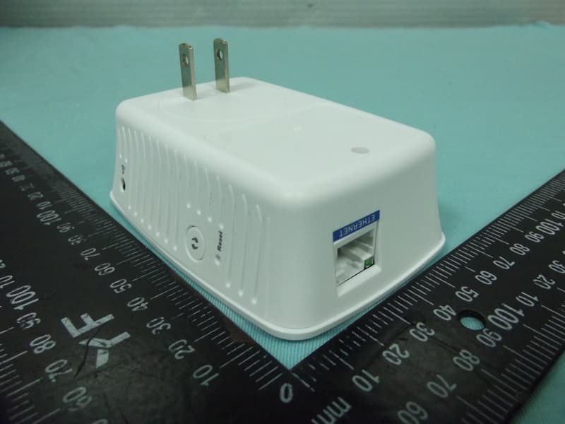
Click to zoom
Application Details
- Equipment Class
- NII - Unlicensed National Information Infrastructure TX
- Date of Grant
- Jan 15, 2015
- Application Purpose
- Original Equipment
- Date of Application
- Jan 15, 2015
- Equipment Note
- Wi-Fi repeater
- Frequency Range
- 5745.00000000 - 5825.00000000
- Company
- LINKSYS LLC
- Country
- United States
Documents & Files
Document Text
Text extracted from the exhibit documents filed with the FCC. Open a document above to read the original.
Users Manual
User Guide RE4100W Introduction This User Guide can help you connect the extender to your network and solve common setup issues. You can find more help from our award-winning, 24/7 customer support at Linksys.com/support. Contents Overview . . . . . . . . . . . . . . . . . . . . . . . . . . . . . . . . . . . . . . . . 1 How to install the range extender................ 2 How to access the browser-based utility .......... 5 Using range extender settings ............... X Using Wi-Fi Protected Setup..................... 7 How to use Site Survey.......................... 9 Troubleshooting................................ 10 Specifications.................................. 13 Overview Front The light on the front of the range extender gives you information about power and Wi-Fi Protected Setup. Use Wi-Fi Protected Setup to automatically and securely connect compatible wireless devices such as wireless printers. Power Light Status/ description Blinking Green • Powered on • Resetting to factory defaults • Upgrading its firmware Solid Green • Ready to use Solid amber • Weak connection with the router Fix: Unplug the extender, and move it closer to the router Blinking Orange • Cannot establish a connection • Other error Fix: Unplug the extender, plug it back in, wait two seconds, reconnect to your network Side Power Switch European versions only. Audio Port Connect the extender to your speaker. Wi-Fi Protected Setup Button Use Wi-Fi Protected Setup to automatically and securely add compatible wireless devices to your network. Refer to Using Wi-Fi Protected Setup on page 7. Reset Press and hold for about five seconds to reset to factory defaults. You can also restore the defaults from the Administration > Factory Defaults screen in the extender’s browser- based utility. Bottom Ethernet (blue) Connect wired devices to your wireless network with Ethernet (network) cables. The green light turns on when an Ethernet device is connected and active on this port. The light blinks when the extender is sending or receiving data over the Ethernet port. How to install the range extender Before setup, unplug or disconnect any range extenders on the network. 1. Plug in the range extender midway between your router and the area without Wi-Fi. Be sure you have at least 50% of your router’s Wi-Fi signal at that point on the device you will use for setup. The setup software will help you find the best spot if you have trouble. 2. Wait for a solid light on the cover of the range extender. It could take up to two minutes. On a computer, phone or tablet, connect to the Wi-Fi network “Linksys Extender Setup.” • Windows 7 and Windows 8 will ask you, “Do you want to set up your network?” Click the link, “Connect to network without setting it up.” 3. If setup doesn’t start automatically, open a browser to http://extender.linksys.com TIP You can also connect the range extender by using Wi-Fi Protected Setup. For more information, see “Using Wi-Fi Protected Setup” on page 7. How to access the browser-based utility After setting up the extender use the extender’s browser-based utility to change any settings. Windows XP: TIP To follow these instructions, enable UPnP: 1. Click Start, Control Panel, Add or Remove Program, then click Add/Remove Windows Components. 2. Select Network Services, then click Details. 3. Select UPnP User Interface, then click OK. 1. Open Windows Explorer. Click My Network Places on the left panel. 2. Look for the RE4100W icon on the right panel. (You might be required to change the firewall settings to allow the display of networked computers. Refer to your operating system’s help for instructions.) 3. Double-click the RE4100W icon. A web browser will open and prompt you to enter your User name and Password. 4. Leave the User name field blank, and enter the default password “admin.” 5. Click OK. Windows 8, Windows 7, or Vista: 1. Open Windows Explorer (File Explorer in Windows 8). Click Network. Look for the RE4100W icon on the right panel. (You might be required to change the firewall settings to allow the display of networked computers. Refer to your operating system’s help for instructions.) 2. Right-click the RE4100W icon. Click Properties. Click on the address link in Device webpage. A web browser will open and prompt you to enter a User name and Password. 3. Leave the User name blank, and enter the default password “admin.” 4. Click OK. Mac OS X: 1. Open Safari. Click the book icon. Click Bonjour on the left panel. Look for the RE4100W icon on the bottom right panel. 2. Double-click the RE4100W icon. 3. Leave the User name blank, and enter the default password “admin.” 4. Click OK. Using range extender settings Click Help on the right side of the screen for additional information on the screen’s options. Changes to settings will not be effective until you click Save Settings at the bottom of the screen. You also can click Cancel Changes to clear any changes. Using Wi-Fi Protected Setup Wi-Fi Protected Setup™ makes it easy to connect your extender to your network, and connect other devices to your network through the extender. Wi-Fi Protected Setup light activity WPS Light Status/ description Blinking Green • When WPS connection is in process Solid Green • When WPS connection is successful Blinking amber for two minutes • When WPS cannot establish connection or encounters a problem Fix: wait a few seconds after LED stops blinking and try again Connecting the extender to an existing access point If your access point or router supports it, you can use Wi-Fi Protected Setup to connect the range extender to the access point or router. Choose from the setup methods below to connect the extender. NOTE If you have an access point or a router that does not support Wi-Fi Protected Setup, note the wireless settings, and then manually configure the extender. Connecting with the Wi-Fi Protected Setup Button Use this method if your router or access point has a Wi-Fi Protected Setup button. 1. Press the Wi-Fi P…
Text truncated - open the document above for the full version.
Users Manual
Regulatory Information RE4100W .3".3" .3".3" 1 Wireless regulatory information FCC Statement This device complies with Part 15 of the FCC Rules. Operation is subject to the following two conditions: (1) This device may not cause harmful interference, and (2) this device must accept any interference received, including interference that may cause undesired operation. This product has been tested and complies with the specifications for a Class B digital device, pursuant to Part 15 of the FCC Rules. These limits are designed to provide reasonable protection against harmful interference in a residential installation. This equipment generates, uses, and can radiate radio frequency energy and, if not installed and used according to the instructions, may cause harmful interference to radio communications. However, there is no guarantee that interference will not occur in a particular installation. If this equipment does cause harmful interference to radio or television reception, which is found by turning the equipment off and on, the user is encouraged to try to correct the interference by one or more of the following measures: • Reorient or relocate the receiving antenna • Increase the separation between the equipment and devices • Connect the equipment to an outlet other than the receiver’s • Consult a dealer or an experienced radio/TV technician for assistance fCC Caution: Any changes or modifications not expressly approved by the party responsible for compliance could void the user’s authority to operate this equipment. IEEE 802.11b or 802.11g operation of this product in the USA is firmware-limited to channels 1 through 11. The device for the band 5150-5250 MHz is only for indoor usage to reduce the potential for harmful interference to co-channel mobile satellite systems. FCC Radiation Exposure Statement This equipment complies with FCC radiation exposure limits set forth for an uncontrolled environment. This equipment should be installed and operated with minimum distance 25 cm between the radiator and your body. This device and it’s antennas(s) must not be co-located or operating in conjunction with any other antenna or transmitter except in accordance with FCC multi-transmitter product procedures. Industry Canada Statement CAN ICES-3 (B)/NMB-3 (B) This device complies with Industry Canada license-exempt RSS standard(s). Operation is subject to the following two conditions: (1) this device may not cause interference, and (2) this device must accept any interference, including interference that may cause undesired operation of the device. For product available in the USA/Canada market, only channel 1~11 can be operated. Selection of other channels is not possible. 4 Prescriptions supplémentaires pour la bande 5600-5650 MHz Jusqu’à nouvel ordre, les appareils faisant l’objet de la présente section ne doivent pas transmettre dans la bande 5600-5650 MHz, afin que les radars météorologiques d’Environnement Canada fonctionnant dans cette bande soient protégés. Wireless Disclaimer The maximum performance for wireless is derived from IEEE Standard 802.11 specifications. Actual performance can vary, including lower wireless network capacity, data throughput rate, range and coverage. Performance depends on many factors, conditions and variables, including distance from the access point, volume of network traffic, building materials and construction, operating system used, mix of wireless products used, interference and other adverse conditions. Avis de non-responsabilité concernant les appareils sans fil Les performances maximales pour les réseaux sans fil sont tirées des spécifications de la norme IEEE 802.11. Les performances réelles peuvent varier, notamment en fonction de la capacité du réseau sans fil, du débit de la transmission de données, de la portée et de la couverture. Les performances dépendent de facteurs, conditions et variables multiples, en particulier de la distance par rapport au point d’accès, du volume du trafic réseau, des matériaux utilisés dans le bâtiment et du type de construction, du système d’exploitation et de la combinaison de produits sans fil utilisés, des interférences et de toute autre condition défavorable. 5 WARNING: Do not use this product near water, for example, in a wet basement or near a swimming pool. WARNING: Avoid using this product during an electrical storm. There may be a remote risk of electric shock from lightning. WARNING: This product may contain chemicals, known to the State of California to cause cancer, and birth defects or other reproductive harm. Wash hands after handling. WARNING: The power adaptor is the equipment ́s disconnection device. The power outlet must be located nearby the equipment and its access must be easy. ]Arabic[ العربية تحذير: لا تستخدم هذا المنتج بالقرب من الماء، على سبيل المثال، في طابق سفلي رطب أو بالقرب من حمام سباحة. تحذير: تجنب استخدام المنتج أثناء العاصفة الرعدية. قد يكون هناك خطر بعيد للتعرض لصدمة كهربائية بسبب البرق. تحذير: مهايئ الطاقة هو أداة الفصل في هذا الجهاز. يجب وضع الجهاز بالقرب من منفذ الطاقة بحيث يسهل الوصول إليه. Safety Notices ПРЕДУПРЕЖДЕНИЕ: Не използвайте устройството в близост до вода, напр. във влажно мазе или до плувен басейн. ПРЕДУПРЕЖДЕНИЕ: Изключването на оборудването се извършва чрез захранващия адаптер. Електрическият контакт трябва да бъде \ разположен в близост до оборудването леснодостъпен. ПРЕДУПРЕЖДЕНИЕ: Избягвайте да използвате това устройство по време на буря. Възможно е да съществува несъществен риск от електрически удар от светкавица. Български [Bulgarian] UPOZORENJE: Ne koristite proizvod u blizini vode, primjerice u mokrom podrumu ili blizu bazena. UPOZORENJE: Prilagodnik za napajanje je uređaj za isključivanje opreme. Strujna utičnica mora biti smještena blizu opreme i mora biti lako dostupna. UPOZORENJE: Izbjegavajte koristiti proizvod tijekom grmljavinskog vremena. Postoji rizik od strujnog udara zbog grmljavine. Hrvatski [Croatian] English 6 UPOZORNĚNÍ: Nepoužívejte tento prod…
Text truncated - open the document above for the full version.
Cover Letter(s)
RF_160, Issue 02 Declaration of Authorization We Name: LINKSYS LLC Address: 121 Theory Drive City: Irvine State: California Country: United States Declare that: Name Representative of agent: Ms. Cathy Wang Agent Company name: BTL Inc. Address: B1, No. 37, Lane 365, YangGuang St., NeiHu District 114, Taipei, Taiwan City: Taipei Country: Taiwan is authorized to apply for Certification and signing related documents of the following product(s), including 731 form(s): Product description: Wi-Fi repeater Type designation: RE4100W Trademark: Linksys on our behalf. Date: 2014-12-04 City: Irvine Name: Daniel Wesey Function: Director of Global Regulatory Compliance Signature: . Notes: (1): Required for FCC application (2): For FCC it must be the Grantee Code “owner” or the authorized agent.
Cover Letter(s)
FCC, Request for non-disclosure Date: 10-Aug-09 RF_501, Issue 5 Page 1 of 1 Company Name: LINKSYS LLC Address: 121 Theory Drive City: Irvine Country: United States To: Telefication B.V., Dept. FCC TCB Edisonstraat 12A 6902 PK ZEVENAAR The Netherlands Subject: Request for confidentiality FCC ID: Q87-RE4100W Reference number: ###### Dear FCC TCB, 1. Long-Term Confidentiality Pursuant to 47 CFR Section 0.459(a) & (b), we hereby requests non-disclosure and confidential treatment of the following materials submitted in support of FCC certification application: Bill(s) of Material Block Diagrams Operational Description Schematic Diagrams Tune-up Procedure Above materials contain secrets, proprietary and technical information, which would customarily be guarded from competitors under 47 CFR, section 0.457(d)(2). Disclosure or publication or any portion of this company confidential material to other parties could cause substantial competitive harm and provide unjustified benefits for competitors. 2. Short-Term Confidentiality (STC) Pursuant to Public Notice DA 04-1705 of the Commission’s policy, in order to comply with the marketing regulations in 47 CFR §2.803 and the importation rules in 47 CFR §2.1204, applicant hereby requests Short-Term Confidential treatment of the following materials (note 1): Internal Photos User’s Manual Test Set-up Photos External Photos Justification: Planned Release Date STC: (notes 2, 3, 4, 5) Date: 2014-12-04 Name and signature of applicant: Daniel Wesey Notes: 1) A document or type of document can only have ONE type of confidentiality! 2) Short-Term confidentiality is in principle for 45 days from date of grant; it can be extended max 3 times (total time 180 days max.)! 3) FCC must be informed when marketing begins earlier. 4) Release takes place automatically thus extension must be requested in time. Telefication does not remind you of this! 5) Request for extension or for release must be received by Telefication at least 7 days before date of actual marketing or before expiration of the STC period
Cover Letter(s)
CERTIFICATE OF COMPLIANCE Authorized under Declaration of Conformity according to 47 CFR, Part 2 and Part 15 of the FCC Rules. The product listed in follows was (were) tested in the BTL EMC Laboratory to comply with the criteria limits Class B of conducted and radiated emissions of the Technical Standards FCC Part 15, Subpart B, established by the FCC, USA. Equipment Wi-Fi repeate r Model Name RE4100W Brand Name Linksys Applicant Linksys LLC. Address 121 Theory Drive, Irvine, California, 92617, United States of America Standard(s) FCC Part 15, Subpart B: 2013 ICES-003 Issue 5: 2012 ANSI C63.4-2009 Report(s) BTL-FCCE-1-1411127 The test data, data evaluation, and equipment configuration contained in our test report(s) above was(were) obtained utilizing the test procedures, test instruments, test sites that has been accredited by the Authority of TAF according to the ISO-17025 quality assessment standard and technical standard(s). The test data contained in the referenced test report relate only to the EUT sample and item(s) tested. Andy Chiu Authorized Signatory BTL INC. B1, No. 37, Lane 365, Yang-Guang St., Nei-Hu District, Taipei City 114, Taiwan. TEL:+886-2-2657-3299 FAX:+886-2-2657-3331
External Photos
Project No.: 1411127 Page 2 of 14 Project No.: 1411127 Page 3 of 14
ID Label/Location Info
45.52±0.15mm 36.37±0.15mm FCC ID: Q87-RE4100W IC: 3839A-RE4100W RE4100W 5V 2.0A File Name RE4100W US_CA product label Belkin P/N Date 2014/09/19 RE4100W_US/CA Product label Pantone Cool grey 2C Product Label (特白龍+adhesive ,total=0.12mm) Pantone Black
Internal Photos
Project No.: 1411127 Page 4 of 14 Project No.: 1411127 Page 5 of 14 Project No.: 1411127 Page 6 of 14 Project No.: 1411127 Page 7 of 14 Project No.: 1411127 Page 8 of 14 Project No.: 1411127 Page 9 of 14 Project No.: 1411127 Page 10 of 14 Project No.: 1411127 Page 11 of 14 Project No.: 1411127 Page 12 of 14 Project No.: 1411127 Page 13 of 14 Project No.: 1411127 Page 14 of 14
Test Report
Report No.: BTL-FCCP-2-1411127 Page 1 of 18 5 FCC Radio Test Report FCC ID: Q87-RE4100W This report concerns (check one): Original Grant Class II Change Project No. : 1411127 Equipment : Wi-Fi repeater Model Name : RE4100W Applicant : Linksys LLC. Address : 121 Theory Drive, Irvine, California, 92617, United States of America Date of Receipt : Nov. 17, 2014 Date of Test : Nov. 17, 2014 ~ Dec. 06, 2014 Issued Date : Dec. 08, 2014 Tested by : BTL Inc. Testing Engineer : (David Mao) Technical Manager : (Leo Hung) Authorized Signatory : (Steven Lu) BTL INC. No.3, Jinshagang 1st Road, Shixia, Dalang Town, Dongguan, Guangdong, China. TEL: +86-769-8318-3000 FAX: +86-769-8319-6000 Report No.: BTL-FCCP-2-1411127 Page 2 of 18 5 Declaration BTLrepresents to the client that testing is done in accordance with standard procedures as applicable and that test instruments used has been calibrated with the standards traceable to National Measurement Laboratory (NML) of R.O.C., or National Institute of Standards and Technology (NIST) of U.S.A. BTL's reports apply only to the specific samples tested under conditions. It is manufacture’s responsibility to ensure that additional production units of this model are manufactured with the identical electrical and mechanical components. BTLshall have no liability for any declarations, inferences or generalizations drawn by the client or others from BTLissued reports. BTL’s reports must not be used by the client to claim product endorsement by the authorities or an y agency of the Government. This report is the confidential property of the client. As a mutual protection to the clients, the public and BTL-self, extracts from the test report shall not be reproduced except in full with BTL’s authorized written approval. BTL’s laboratory quality assurance procedures are in compliance with the ISO Guide 17025 requirements, and accredited by the conformity assessment authorities listed in this test report. Limitation For the use of the authority's logo is limited unless the Test Standard(s)/Scope(s)/Item(s) mentioned in this test report is (are) included in the conformity assessment authorities acceptance respective. Report No.: BTL-FCCP-2-1411127 Page 3 of 18 5 Table of Contents Page 1 . CERTIFICATION 7 2 . SUMMARY OF TEST RESULTS 8 2.1 TEST FACILITY 9 2.2 MEASUREMENT UNCERTAINTY 9 3 . GENERAL INFORMATION 10 3.1 GENERAL DESCRIPTION OF EUT 10 3.2 DESCRIPTION OF TEST MODES 12 3.3 TABLE OF PARAMETERS OF TEXT SOFTWARE SETTING 15 3.4 BLOCK DIAGRAM SHOWING THE CONFIGURATION OF SYSTEM TESTED 16 3.5 DESCRIPTION OF SUPPORT UNITS 16 4 . EMC EMISSION TEST 17 4.1 CONDUCTED EMISSION MEASUREMENT 17 4.1.1 POWER LINE CONDUCTED EMISSION 17 4.1.2 TEST PROCEDURE 17 4.1.3 DEVIATION FROM TEST STANDARD 17 4.1.4 TEST SETUP 18 4.1.5 EUT OPERATING CONDITIONS 18 4.1.6 EUT TEST CONDITIONS 18 4.1.7 TEST RESULTS 18 4.2 RADIATED EMISSION MEASUREMENT 19 4.2.1 RADIATED EMISSION LIMITS 19 4.2.2 TEST PROCEDURE 20 4.2.3 DEVIATION FROM TEST STANDARD 20 4.2.4 TEST SETUP 20 4.2.5 EUT OPERATING CONDITIONS 21 4.2.6 EUT TEST CONDITIONS 21 4.2.7 TEST RESULTS (9KHZ TO 30MHZ) 22 4.2.8 TEST RESULTS (30MHZ TO 1000 MHZ) 22 4.2.9 TEST RESULTS (1GHZ~10 TH HARMONIC) 22 4.3 BAND EDGE MEASUREMENT 23 4.3.1 RADIATED EMISSION LIMITS 23 4.3.2 TEST PROCEDURE 24 4.3.3 TEST SETUP LAYOUT 24 4.3.4 DEVIATION FROM TEST STANDARD 24 4.3.5 EUT OPERATING CONDITIONS 24 4.3.6 TEST RESULTS (BAND EDGE AND FUNDAMENTAL EMISSIONS) 24 5 . 26dB SPECTRUM BANDWIDTH 25 5.1 APPLIED PROCEDURES / LIMIT 25 Report No.: BTL-FCCP-2-1411127 Page 4 of 18 5 Table of Contents Page 5.1.1 TEST PROCEDURE 25 5.1.2 DEVIATION FROM STANDARD 25 5.1.3 TEST SETUP 25 5.1.4 EUT OPERATION CONDITIONS 25 5.1.5 EUT TEST CONDITIONS 26 5.1.6 TEST RESULTS 26 6 . MAXIMUM CONDUCTED OUTPUT POWER 27 6.1 APPLIED PROCEDURES / LIMIT 27 6.1.1 TEST PROCEDURE 27 6.1.2 DEVIATION FROM STANDARD 28 6.1.3 TEST SETUP 28 6.1.4 EUT OPERATION CONDITIONS 28 6.1.5 EUT TEST CONDITIONS 28 6.1.6 TEST RESULTS 28 7 . ANTENNA CONDUCTED SPURIOUS EMISSION 29 7.1 APPLIED PROCEDURES / LIMIT 29 7.1.1 TEST PROCEDURE 29 7.1.2 DEVIATION FROM STANDARD 29 7.1.3 TEST SETUP 29 7.1.4 EUT OPERATION CONDITIONS 29 7.1.5 EUT TEST CONDITIONS 29 7.1.6 TEST RESULTS 29 8 . POWER SPECTRAL DENSITY TEST 30 8.1 APPLIED PROCEDURES / LIMIT 30 8.1.1 TEST PROCEDURE 30 8.1.1 DEVIATION FROM STANDARD 31 8.1.2 TEST SETUP 31 8.1.3 EUT OPERATION CONDITIONS 31 8.1.4 EUT TEST CONDITIONS 31 8.1.5 TEST RESULTS 31 9 . FREQUENCY STABILITY MEASUREMENT 32 9.1 APPLIED PROCEDURES / LIMIT 32 9.1.1 TEST PROCEDURE 32 9.1.2 DEVIATION FROM STANDARD 32 9.1.3 TEST SETUP 33 9.1.4 EUT OPERATION CONDITIONS 33 9.1.5 EUT TEST CONDITIONS 33 9.1.6 TEST RESULTS 33 10 . MEASUREMENT INSTRUMENTS LIST 34 11 . EUT TEST PHOTOS 36 Report No.: BTL-FCCP-2-1411127 Page 5 of 18 5 Table of Contents Page ATTACHMENT A - CONDUCTED EMISSION 40 ATTACHMENT B - RADIATED EMISSION (9KHZ TO 30MHZ) 43 ATTACHMENT C - RADIATED EMISSION (30MHZ TO 1000MHZ) 45 ATTACHMENT D - RADIATED EMISSION (1GHZ~10 TH HARMONIC) 58 ATTACHMENT E - BAND EDGE AND FUNDAMENTAL EMISSIONS 91 ATTACHMENT F - BANDWIDTH 127 ATTACHMENT G - MAXIMUM OUTPUT POWER 140 ATTACHMENT H - ANTENNA CONDUCTED SPURIOUS EMISSION 147 ATTACHMENT I - POWER SPECTRAL DENSITY 158 ATTACHMENT J - FREQUENCY STABILITY 183 Report No.: BTL-FCCP-2-1411127 Page 6 of 18 5 REPORT ISSUED HISTORY Issued No. Description Issued Date BTL-FCCP-2-1411127 Original Issue. Dec. 08, 2014 Report No.: BTL-FCCP-2-1411127 Page 7 of 18 5 1. CERTIFICATION Equipment : Wi-Fi repeater Brand Name : Linksys Model Name : RE4100W Applicant : Linksys LLC. Manufacturer : U-MEDIA Communications, Inc. Address : 3F, No.1, Jin-Shan 8th St., Hsinchu 300, Taiwan, ROC Factory : U-MEDIA Communications, Inc. Address : NO.90, Kuang Fu Nth.Rd., Hsinchu Industrial Park, Hu Kou, Hsinchu 303, Taiwan, R.O.C. Date of Test : Nov. 17, 2014 ~ Dec. 06, 2014 Test Sample : ENGINEERING SAMPLE Standard(s) : FCC Part15, Subpart E(15.407) / ANSI C63.4: 2009 FCC KDB 789033 D02 General UNII Test Pro…
Text truncated - open the document above for the full version.
Test Setup Photos
Report No.: BTL-FICP-1-1411127 Page 31 of 149 10. EUT TEST PHOTO Conducted Measurement Photos Report No.: BTL-FICP-1-1411127 Page 32 of 149 Radiated Measurement Photos 9KHz to 30MHz Report No.: BTL-FICP-1-1411127 Page 33 of 149 Radiated Measurement Photos 30MHz to 1000MHz Report No.: BTL-FICP-1-1411127 Page 34 of 149 Radiated Measurement Photos Above 1000MHz
Contact Information
Applicant
Po-Wen Cheng(Regulatory Compliance Manager)
Technical Contact
Non-Technical Contact
BTL Inc.Cathy Wang
[email protected]86-769-83183000
Test Firm
BTL Inc.Daisy Dai
Technical Specifications
| # | Rule Parts | Frequency Range | Power Output |
|---|---|---|---|
| 2 | 15E | 5.75 GHz - 5.83 GHz | 130.00 mW |
Other Applications from LINKSYS LLC

Q87-WDS060
Aug 11, 2020WiFi Smart Light Switch with Dimmer
Equipment Class
DTS - Digital Transmission System
Q87-03564
Jun 28, 2020Linksys Tri-Band Wireless-AC Router
Equipment Class
NII - Unlicensed National Information Infrastructure TX
Q87-03566
Jun 23, 2020Linksys Tri-Band Wireless-AC Router
Equipment Class
NII - Unlicensed National Information Infrastructure TX
Q87-03530
Apr 29, 2020Linksys MAX-STREAM AC1900+ WiFi Range Extender
Equipment Class
NII - Unlicensed National Information Infrastructure TX
Q87-08151
Mar 30, 2020Linksys Dual-Band 802.11ax Wireless Router
Equipment Class
DTS - Digital Transmission System