Q87-WAG54GV2MWLAN 802.11g MiniPCI Card
LINKSYS LLC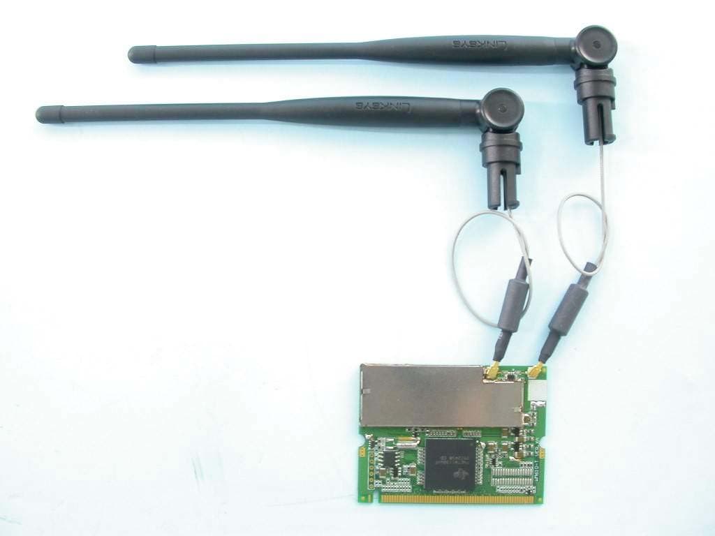
Click to zoom
Application Details
- Equipment Class
- DTS - Digital Transmission System
- Date of Grant
- Mar 23, 2004
- Application Purpose
- Original Equipment
- Date of Application
- Mar 23, 2004
- Equipment Note
- WLAN 802.11g MiniPCI Card
- Frequency Range
- 2412.00000000 - 2462.00000000
- Company
- LINKSYS LLC
- Country
- United States
Documents & Files
Document Text
Text extracted from the exhibit documents filed with the FCC. Open a document above to read the original.
Users Manual
Configuration Utility User’s Guide Revision 0.1 1 1 Introduction...........................................................................................................................3 1.1 List of abbreviations and Terms............................................................................................3 2 Installation.............................................................................................................................4 3 Using the TI WLAN CU....................................................................................................... 5 3.1 The Main (Status) Screen.......................................................................................................6 3.2 The Modify Property Sheet....................................................................................................9 3.2.1 The New Connection tab............................................................................9 3.2.2 Advanced tab............................................................................................11 3.3 The Advanced Properties Screen......................................................................................... 12 3.4 The Privacy Screen................................................................................................................ 14 3.4.1 The WEP Screen.......................................................................................15 3.4.2 The CCX Configuration Screen................................................................16 3.5 The Statistics Screen..............................................................................................................17 3.6 The About Screen...................................................................................................................18 3.7 Debug Screen..........................................................................................................................19 3.7.1 Debug Tab activation................................................................................19 3.7.2 Debug Screen options...............................................................................20 Revi si on 0.1 2 Technology,Inc. 1 Introduction The configuration utility provides displaying and changing parameters of the TI WLAN driver. 1.1 List of abbreviations and Terms AES - Advanced Encryption Standard AP - Access Point BSS - Basic Service Set BSSID - Basic Service Set Identifier CU - Configuration Utility FCS - Frame Check Sequence GUI - Graphical User Interface IBSS - Independent Basic Service Set LEAP - Lightweight Extensible Authentication Protocol MAC - Medium Access Control MSDU - MAC Service Data Unit PBCC - Packet Broadcast Control Channel PRS - Product Requirements Specification RSSI - Received Signal Strength Indication SSID - Service Set Identifier SSN - Sub System Number TI - Texas Instruments Inc. TKIP - Temporal Key Integrity Protocol WEP - Wired Equivalent Privacy WiFi - Wireless Fidelity WPA - WiFi Protected Access WLAN - Wireless Local Area Network Revision 0.1 3 2 Installation Revision 0.1 4 3 Using the TI WLAN CU Important Notes: • In case that the device was not installed properly or that it is disconnected, all buttons, combo boxes, edit boxes etc. will be disabled. Also the status text in the main window will be set to Driver not loaded. • To save any changes – press the Apply button. Changes will not be saved if changed focus to another tab without previously clicking the Apply button. • Pressing the OK / Cancel button from the main property sheet will minimize the application to the task bar. In case that there were changes, clicking the Cancel button will return the displayed data to the one stored on the driver. Another click will minimize the application to the task bar. Left click the application icon on the task bar, or right click and choose Restore to restore it. Choose Exit to exit the application. Revision 0.1 5 3.1 The Main (Status) Screen The Main Screen is the main page for the CU. It contains the available 802.11 networks and the current configuration basic data. It enables rescanning the network, modifying the current configuration parameters and connecting to each one of the listed SSIDs. It also enables activating and deactivating of using an external configuration. Revision 0.1 6 Getting Started: In order to connect to a network, do the following: 1) In the Available Networks Window the currently available networks are displayed. In order to connect to a specific network – select the appropriate raw (will be highlighted as a result) 2) Click on the Connect button (another option is to double click the appropriate raw). After doing so, the CU will attempt associating with the chosen network. If there are no available networks on the available networks window, you can choose to rescan for currently available networks by pressing the Rescan button. After choosing a network, a basic connection data will be displayed on the screen. See Displayed data section for details . If no network is available or refreshing the available networks list is desired – click on the Rescan button. Displayed data: Status – can be one the following: • Driver not loaded – driver not installed or not inserted. • Disconnected from network – disconnected from current configured SSID. • Connecting to network – while in the process of connecting. • Connected to network – connected to current configured SSID. • Scanning network – scanning network for available SSIDs. • Not connected to network – sidle status Current configuration - provides read-only status information of the current active connection. • Pref: SSID - Preferred Service Set Identifier. • BSS Type - Basic Service Set Type. • BSSID - Basic Service Set Identifier. • Channe - the channel number through which we are connected. • Tx Rate - current rate used for transmitting frames. For more information, see section 3.2.1 Signal quality – displays the Received Signal Streng…
Text truncated - open the document above for the full version.
Cover Letter(s)
FCC ID: Q87-WAG54GV2M ADT No. 930211R02 Modular Approval Request Letter Advance Data Technology March 1, 2004 Dear Application Examiner, Cisco-Linksys, LLC. It’s WLAN 802.11g MiniPCI Card, FCC ID: Q87-WAG54GV2M, would like to have your authorization as a limited modular approval specific to the mobile device such as Access Point and Router. The requirements of Public Notice DA00-1407 have been met and shown on the following statements. 1. “The modular transmitter must have its own RF shielding.”: The radio portion of this module has been shielded, please see exhibition External Photo. 2. “The modular transmitter must have buffered modulation/data inputs.” The EUT has buffered data inputs, it is integrated in chip TNET1130 BGA288. 3. “The modular transmitter must have its own power supply regulation.” The chips IF converter and RF/IF converter which will influence the frequency radiation, have to be 2.85V DC powered. The mini-PCI interface provides 3.3Vdc, so there are regulators in front of these chips, the part number of this regulator is TPS793285DBVR. 4. “The modular transmitter must comply with the antenna requirements of section 15.203 and 15.204(C).” The EUT meets the FCC antenna requirements. The spurious emission, unique antenna connector and photo of antennas are shown in the test report. 5. “The modular transmitter must be tested in a stand-alone configuration” The EUT was tested in a stand-alone configuration via a PCMCIA to mini-PCI extender. Please see section Photographs of Test Configuration in the test report, the EUT was plugged in this extender. 6. “The modular transmitter must be labeled with its own FCC ID number.” Please see exhibition Label Sample for the FCC ID of this module. And also in the exhibition Users Manual, there are instructions give to the OEM on how to label the end product. FCC ID: Q87-WAG54GV2M ADT No. 930211R02 7. “The modular transmitter must comply with any specific rule or operating requirements applicable to the transmitter and the manufacturer must provide adequate instructions along with the module to explain any such requirements.” The EUT is compliant with all applicable FCC rules. Detail instructions for maintaining compliance are given in the Users Manual. 8. “The modular transmitter must comply with any applicable RF exposure requirements.” The EUT is compliant with all applicable RF exposure requirements. RF Exposure is addressed in the RF exposure exhibition. Please contact me if you have any further questions. Thanks for your attention. Best Regards, Ellis Wu Manager Advance Data Technology
External Photos
Page 1 CONSTRUCTION PHOTOS OF EUT
ID Label/Location Info
Label Location
Internal Photos
Page 2 Page 3 Page 4 Page 5
Operational Description
FCC ID: Q87-WAG54GV2M Report No. RF930211R02 Operational Description This device is a WLAN 802.11g MiniPCI Card which operates in the 2.4GHz frequency spectrum with throughput of up to 54Mbps which OFDM technique will be applied. If the signal to noise radio is too poor which could not support 54Mbps, the 11Mbps data rate with CCK technique will be applied. The transmitter of the EUT is powered by notebook and connected with managing computer through PCMCIA. The antenna is External(monopole) Antenna with UFL connector. Under normal use condition, the user has to keep at least 20cm separation distance between radiator and the body of the user. The other instruction, please have a look at the users manual.
RF Exposure Info
FCC ID: Q87-WAG54GV2M Report No: SA930211R02 1 RF EXPOSURE REPORT REPORT NO.: SA930211R02 MODEL NO.: WAG54GV2M ACCORDING: FCC Guidelines for Human Exposure IEEE C95.1 APPLICANT: Cisco-Linksys, LLC ADDRESS: 17401, Armstrong Ave, Irvine, California, United States ISSUED BY: Advance Data Technology Corporation LAB LOCATION: 47 14th Lin, Chiapau Tsun, Linko, Taipei, Taiwan, R.O.C. FCC ID: Q87-WAG54GV2M Report No: SA930211R02 2 RF Exposure Measurement (Mobile Device) 1. Introduction In this document, we try to prove the safety of radiation harmfulness to the human body for our product. The limit for Maximum Permissible Exposure (MPE) specified in FCC 1.1310 is followed. The Gain of the antenna used in this product is measured in a Fully Anechoic Chamber (FAC) calibrated for antenna measurement in ADT, and also the maximum total power input to the antenna is measured. Through the Friis transmission formula and the maximum gain of the antenna, we can calculate the distance, away from the product, where the limit of MPE is reached. Although the Friis transmission formula is a far field assumption, the calculated result of that is an over-prediction for near field power density. We will take that as the worst case to specify the safety range. 2. RF Exposure Limit According to FCC 1.1310: The criteria listed in the following table shall be used to evaluate the environmental impact of human exposure to radio-frequency (RF) radiation as specified in 1.1307(b) LIMITS FOR MAXIMUM PERMISSIBLE EXPOSURE (MPE) Frequency Range (MHz) Electric Field Strength (V/m) Magnetic Field Strength (A/m) Power Density (mW/cm 2 ) Average Time (minutes) (A)Limits For Occupational / Control Exposures 300-1500......F/3006 1500-100,000......56 (B)Limits For General Population / Uncontrolled Exposure 300-1500......F/15006 1500-100,000......1.030 F = Frequency in MHz FCC ID: Q87-WAG54GV2M Report No: SA930211R02 3 3. Friis Formula Friis transmission formula : Pd = (Pout*G) / (4*pi*r 2 ) where Pd = power density in mW/cm 2 Pout = output power to antenna in mW G = gain of antenna in linear scale Pi = 3.1416 R = distance between observation point and center of the radiator in cm If we know the maximum Gain of the antenna and the total power input to the antenna, through the calculation, we will know the MPE value at distance r. Ref. : David K. Cheng, Field and Wave Electromagnetics, Second Edition, Page 640, Eq. (11-133). 4. EUT Operating condition The software provided by Manufacturer enabled the EUT to transmit and receive data at lowest, middle and highest channel individually. 5. Classification This modular is specified to be installed in access point which is connected with host through wire. So it is easy to be re-located in the place where at least 20cm far away from the body of the user. Warning statement to the user for keeping at least 20cm or more separation distance with the antenna should be included in users manual. So, this device is classified as Mobile Device. FCC ID: Q87-WAG54GV2M Report No: SA930211R02 4 6. Test Results 6.1 Antenna Gain The maximum Gain measured in Fully Anechoic Chamber is 3.3dBi or 2.138 (numeric) 6.2 Output Power Into Antenna & RF Exposure value at distance 20cm: For 802.11b (CCK technique): Channel Channel Frequency (MHz) Output Power to Antenna (mW) Power Density (mW/cm 2 ) Limit of Power Density (mW/cm 2 ) 1241253.7030.0231 6243756.2340.0241 11246252.4810.0221 For 802.11g (OFDM technique): Channel Channel Frequency (MHz) Output Power to Antenna (mW) Power Density (mW/cm 2 ) Limit of Power Density (mW/cm 2 ) 1241240.2720.0171 6243742.1700.0181 11246240.5510.0171
Test Report
FCC ID: Q87-WAG54GV2M Report No.: RF930211R021Issued: February 27, 2004 FCC TEST REPORT REPORT NO.: RF930211R02 MODEL NO.: WAG54GV2M RECEIVED: February 11, 2004 TESTED: February 12 ~ February 27, 2004 APPLICANT: Cisco-Linksys, LLC ADDRESS: 121 Theory Drive Irvine, CA 92612 (USA) ISSUED BY: Advance Data Technology Corporation LAB LOCATION: 47 14th Lin, Chiapau Tsun, Linko, Taipei, Taiwan, R.O.C. This test report consists of 69 pages in total. It may be duplicated completely for legal use with the approval of the applicant. It should not be reproduced except in full, without the written approval of our laboratory. The client should not use it to claim product endorsement by CNLA or any government agencies. The test results in the report only apply to the tested sample. 0528 ILAC MRA FCC ID: Q87-WAG54GV2M Report No.: RF930211R022Issued: February 27, 2004 Table of Contents 1CERTIFICATION ........................................................................................... 4 2SUMMARY OF TEST RESULTS................................................................... 5 3GENERAL INFORMATION ........................................................................... 6 3.1GENERAL DESCRIPTION OF EUT.............................................................. 6 3.2DESCRIPTION OF TEST MODES................................................................ 7 3.3GENERAL DESCRIPTION OF APPLIED STANDARDS ............................... 7 3.4DESCRIPTION OF SUPPORT UNITS .......................................................... 8 3.5CONFIGURATION OF SYSTEM UNDER TEST........................................... 8 4TEST TYPES AND RESULTS....................................................................... 9 4.1CONDUCTED EMISSION MEASUREMENT ................................................ 9 4.1.1LIMITS OF CONDUCTED EMISSION MEASUREMENT.............................. 9 4.1.2TEST INSTRUMENTS .................................................................................. 9 4.1.3TEST PROCEDURES................................................................................. 10 4.1.4DEVIATION FROM TEST STANDARD ....................................................... 10 4.1.5TEST SETUP ...............................................................................................11 4.1.6EUT OPERATING CONDITIONS.................................................................11 4.1.7TEST RESULTS.......................................................................................... 12 4.2RADIATED EMISSION MEASUREMENT ................................................... 18 4.2.1LIMITS OF RADIATED EMISSION MEASUREMENT................................. 18 4.2.2TEST INSTRUMENTS ................................................................................ 19 4.2.3TEST PROCEDURES................................................................................. 20 4.2.4DEVIATION FROM TEST STANDARD ....................................................... 20 4.2.5TEST SETUP .............................................................................................. 21 4.2.6EUT OPERATING CONDITIONS................................................................ 21 4.2.7.TEST RESULTS.......................................................................................... 22 4.36dB BANDWIDTH MEASUREMENT .......................................................... 30 4.3.1LIMITS OF 6dB BANDWIDTH MEASUREMENT ........................................ 30 4.3.2TEST INSTRUMENTS ................................................................................ 30 4.3.3TEST PROCEDURE ................................................................................... 31 4.3.4DEVIATION FROM TEST STANDARD ....................................................... 31 FCC ID: Q87-WAG54GV2M Report No.: RF930211R023Issued: February 27, 2004 4.3.5TEST SETUP .............................................................................................. 31 4.3.6EUT OPERATING CONDITIONS................................................................ 31 4.3.7TEST RESULTS.......................................................................................... 32 4.4MAXIMUM PEAK OUTPUT POWER .......................................................... 40 4.4.1LIMITS OF MAXIMUM PEAK OUTPUT POWER MEASUREMENT ........... 40 4.4.2TEST INSTRUMENTS ................................................................................ 40 4.4.3TEST PROCEDURES................................................................................. 41 4.4.4DEVIATION FROM TEST STANDARD ....................................................... 41 4.4.5TEST SETUP .............................................................................................. 41 4.4.6EUT OPERATING CONDITIONS................................................................ 41 4.4.7TEST RESULTS.......................................................................................... 42 4.5POWER SPECTRAL DENSITY MEASUREMENT...................................... 44 4.5.1LIMITS OF POWER SPECTRAL DENSITY MEASUREMENT ................... 44 4.5.2TEST INSTRUMENTS ................................................................................ 44 4.5.3TEST PROCEDURE ................................................................................... 45 4.5.4DEVIATION FROM TEST STANDARD ....................................................... 45 4.5.5TEST SETUP .............................................................................................. 45 4.5.6EUT OPERATING CONDITIONS................................................................ 45 4.5.7TEST RESULTS.......................................................................................... 46 4.6BAND EDGES MEASUREMENT ................................................................ 54 4.6.1LIMITS OF BAND EDGES MEASUREMENT ............................................. 54 4.6.2TEST INSTRUMENTS ..............................................…
Text truncated - open the document above for the full version.
Test Setup Photos
CONDUCTED EMISSION TEST RADIATED EMISSION TEST
Contact Information
Applicant
Po-Wen Cheng(Regulatory Compliance Manager)
Technical Contact
Advance Data Technology Corp.Ellis Wu
[email protected]+886-3-327-0910
13-1 Lane 19 WenShan 3rd Street · Taoyuan · Taiwan
Test Firm
Advance Data Technology CorporationStephen Chen
Technical Specifications
| # | Rule Parts | Frequency Range | Power Output |
|---|---|---|---|
| 1 | 15C | 2.41 GHz - 2.46 GHz | 56.00 mW |
Other Applications from LINKSYS LLC

Q87-WDS060
Aug 11, 2020WiFi Smart Light Switch with Dimmer
Equipment Class
DTS - Digital Transmission System
Q87-03564
Jun 28, 2020Linksys Tri-Band Wireless-AC Router
Equipment Class
NII - Unlicensed National Information Infrastructure TX
Q87-03566
Jun 23, 2020Linksys Tri-Band Wireless-AC Router
Equipment Class
NII - Unlicensed National Information Infrastructure TX
Q87-03530
Apr 29, 2020Linksys MAX-STREAM AC1900+ WiFi Range Extender
Equipment Class
NII - Unlicensed National Information Infrastructure TX
Q87-08151
Mar 30, 2020Linksys Dual-Band 802.11ax Wireless Router
Equipment Class
DTS - Digital Transmission System