Q87-WCG200Wireless-G Cable Gateway
LINKSYS LLC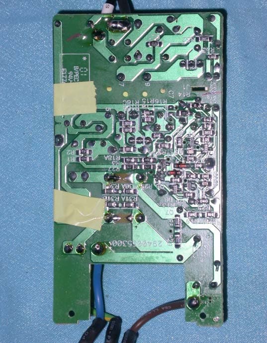
Click to zoom
Application Details
- Equipment Class
- DTS - Digital Transmission System
- Date of Grant
- Jul 14, 2003
- Application Purpose
- Original Equipment
- Date of Application
- Jul 13, 2003
- Equipment Note
- Wireless-G Cable Gateway
- Frequency Range
- 2412.00000000 - 2462.00000000
- Company
- LINKSYS LLC
- Country
- United States
Documents & Files
Document Text
Text extracted from the exhibit documents filed with the FCC. Open a document above to read the original.
Users Manual
L INKSYS WCG200 Cable Modem User’s Manual LINKSYS WCG200 User Manual Safety Notes For Installation Use only the type of power source indicated on the marking labels. Use only the power adapter supplied with the product. Do not overload wall outlet or extension cords as this may increase the risk of electric shock or file. If the power cord is frayed, replace it with a new one. Proper ventilation is necessary to prevent the product overheating. Do not block or cover the slots and openings on the device, which are intended for ventilation and proper operation. It is recommended to mount the product with a stack. Do not place the product near any source of heat or expose it to direct sunshine. Do not expose the product to moisture. Never spill any liquid on the product. Do not attempt to connect with any computer accessory or electronic product without instructions from qualified service personnel. This may result in risk of electronic shock or file. Do not place this product on an unstable stand or table. For Using Power off and unplug this product from the wall outlet when it is not in use or before cleaning. Pay attention to the temperature of the power adapter. The temperature might be high. After powering off the product, power on the product at least 15 seconds later. Do not block the ventilating openings of this product. When the product is expected to be not in use for a period of time, unplug the power cord of the product to prevent it from the damage of storm or sudden increases in rating. For Service Do not attempt to disassemble or open covers of this unit by yourself. Nor should you attempt to service the product yourself, which may void the user’s authority to operate it. Contact qualified service personnel under the following conditions: If the power cord or plug is damaged or frayed. If liquid has been spilled into the product. If the product has been exposed to rain or water. If the product does not operate normally when the operating instructions are followed. If the product has been dropped or the cabinet has been damaged. If the product exhibits a distinct change in performance. Warning This equipment must be installed and operated in accordance with provided instructions and a minimum 20 cm spacing must be provided between computer mounted antenna and person’s body (excluding extremities of hands, wrist and feet) during wireless modes of operation. This device complies with Part 15 of the FCC Rules. Operation is subject to the following two conditions: (1) this device may not cause harmful interference, and (2) this device must accept any interference received, including interference that may cause undesired operation. The antenna(s) used for this transmitter must be installed to provide a separation distance of at least 20 cm from all persons and must not be co-located or operating in conjunction with any other antenna or transmitter. " Caution Any changes or modifications not expressly approved by the party responsible for compliance could void the authority to operate equipment. LINKSYS WCG200 User Manual C C h h a a p p t t e e r r 1 1 : : O O v v e e r r v v i i e e w w 1.1 Physical Outlook 1 1 . . 1 1 - - 1 1 F F r r o o n n t t P P a a n n e e l l The following illustration shows the front panel of the LINKSYS WCG200 Cable Modem. LED Indicators The LEDs on the front panel are described in the table below (from left to right): LED Color Status Description Off Power off. POWER Green On Power on. Off Power off or the initial test is over. Cable Green Blinking To indicate cable modem is on line. Off Power off or the initial test is over. Activity Green On To indicate transmit RF US traffic. Off Power off or the initial test is over. Blinking To indicate Ethernet data traffic. LINE 1~4 Green On Ethernet line is in use. Off Power off or the initial test is over. Blinking To indicate USB data traffic. USB Green On USB interface is in use. Off Power off or the initial test is over. Blinking To indicate wireless data traffic. Wireless Green On Wireless interface is in use. LINKSYS WCG200 User Manual 1 1 . . 1 1 - - 2 2 R R e e a a r r P P a a n n e e l l Power Switch: Standard Power Switch 12 VDC: 12V Power connector RESET︰ Reset-to-Default push button ETHERNET(L1 to L4)︰ 10/100BaseTX RJ-45 connectors, 4 ports auto-sensing & auto-crossover Ethernet switch USB: USB Connector CABLE︰ F-Connector LINKSYS WCG200 User Manual C C h h a a p p t t e e r r 2 2 : : I I n n s s t t a a l l l l a a t t i i o o n n 2.1 Connecting the Cable Modem to Your Computer 2 2 . . 1 1 - - 1 1 I I n n s s t t a a l l l l a a t t i i o o n n P P r r o o c c e e d d u u r r e e f f o o r r E E t t h h e e r r n n e e t t I I n n t t e e r r f f a a c c e e Follow the steps below for proper installation: 1. Make sure your computer meets the system requirements. 2. Connect a coaxial cable (supplied by the local Cable Television Company) to the CABLE connector on the modem. 3. Plug the power adapter into the POWER connector of the modem. 4. Plug the other end of the power adapter into a power outlet. 5. Check CABLE LED. If it is solid ON, the Cable Modem is on-line now. If it is not, contact your service provider. 5. Connect the RJ-45 Ethernet cable to one of the ETHERNET connector on the modem, connect the other end with the 10/100BaseT Ethernet port on your computer. 6. When the connection is established, the client PCs can access the Internet or remote network through the L INKSYS WCG200. Note: You can go to Chapter 3.3 “Setting TCP/IP on client PC” now Below shows the connection status among the cable modem and your computer. LINKSYS WCG200 User Manual 2 2 . . 1 1 - - 2 2 I I n n s s t t a a l l l l a a t t i i o o n n P P r r o o c c e e d d u u r r e e f f o o r r U U S S B B I I n n t t e e r r f f a a c c e e Follow the steps below for proper installation: 1. Make sure your computer meets the system requirements. 2. Connect a coaxial cable (supplied b…
Text truncated - open the document above for the full version.
External Photos
Company : Cisco-Linksys, LLC Page : 1 of 22 Product : Wireless-G Cable Gateway Model : WCG200 Company : Cisco-Linksys, LLC Page : 2 of 22 Product : Wireless-G Cable Gateway Model : WCG200 Company : Cisco-Linksys, LLC Page : 3 of 22 Product : Wireless-G Cable Gateway Model : WCG200 Company : Cisco-Linksys, LLC Page : 4 of 22 Product : Wireless-G Cable Gateway Model : WCG200 Company : Cisco-Linksys, LLC Page : 5 of 22 Product : Wireless-G Cable Gateway Model : WCG200 Company : OEM Page : 6 of 22 Product : Wireless-G Cable Gateway Adapter (1) Model : AD-121ANDT Company : OEM Page : 7 of 22 Product : Wireless-G Cable Gateway Adapter (1) Model : AD-121ANDT Company : OEM Page : 8 of 22 Product : Wireless-G Cable Gateway Adapter (1) Model : AD-121ANDT Company : OEM Page : 9 of 22 Product : Wireless-G Cable Gateway Adapter (1) Model : AD-121ANDT Company : OEM Page : 10 of 22 Product : Wireless-G Cable Gateway Adapter (1) Model : AD-121ANDT Company : OEM Page : 11 of 22 Product : Wireless-G Cable Gateway Adapter (1) Model : AD-121ANDT Company : OEM Page : 12 of 22 Product : Wireless-G Cable Gateway Adapter (1) Model : AD-121ANDT Company : OEM Page : 13 of 22 Product : Wireless-G Cable Gateway Adapter (1) Model : AD-121ANDT Company : DELTA ELECTRONIC, INC Page : 14 of 22 Product : Wireless-G Cable Gateway Adapter (2) Model : ADP-12SB Rev.B Company : DELTA ELECTRONIC, INC Page : 15 of 22 Product : Wireless-G Cable Gateway Adapter (2) Model : ADP-12SB Rev.B Company : DELTA ELECTRONIC, INC Page : 16 of 22 Product : Wireless-G Cable Gateway Adapter (2) Model : ADP-12SB Rev.B Company : DELTA ELECTRONIC, INC Page : 17 of 22 Product : Wireless-G Cable Gateway Adapter (2) Model : ADP-12SB Rev.B Company : DELTA ELECTRONIC, INC Page : 18 of 22 Product : Wireless-G Cable Gateway Adapter (2) Model : ADP-12SB Rev.B Company : DELTA ELECTRONIC, INC Page : 19 of 22 Product : Wireless-G Cable Gateway Adapter (2) Model : ADP-12SB Rev.B Company : DELTA ELECTRONIC, INC Page : 20 of 22 Product : Wireless-G Cable Gateway Adapter (2) Model : ADP-12SB Rev.B Company : DELTA ELECTRONIC, INC Page : 21 of 22 Product : Wireless-G Cable Gateway Adapter (2) Model : ADP-12SB Rev.B Company : DELTA ELECTRONIC, INC Page : 22 of 22 Product : Wireless-G Cable Gateway Adapter (2) Model : ADP-12SB Rev.B
ID Label/Location Info
Company : Cisco-Linksys, LLC Model : WCG200 : Wireless-G Cable Gateway Wireless-G Cable Gateway Model No: WCG200 FCC IDQ87-WCG200 This device complies with part 15 of the FCC Rules. Operation is subject to the following two conditions: [1] this device may not cause harmful interference and [2] this device must accept any interference received, including interference that may cause undesired operation. S/N Made in Taiwan
Internal Photos
Company : Cisco-Linksys, LLC Page : 1 of 13 Product : Wireless-G Cable Gateway Model : WCG200 Company : Cisco-Linksys, LLC Page : 2 of 13 Product : Wireless-G Cable Gateway Model : WCG200 Company : Cisco-Linksys, LLC Page : 3 of 13 Product : Wireless-G Cable Gateway Model : WCG200 Company : Cisco-Linksys, LLC Page : 4 of 13 Product : Wireless-G Cable Gateway Model : WCG200 Company : Cisco-Linksys, LLC Page : 5 of 13 Product : Wireless-G Cable Gateway Model : WCG200 Company : Cisco-Linksys, LLC Page : 6 of 13 Product : Wireless-G Cable Gateway Model : WCG200 Company : Cisco-Linksys, LLC Page : 7 of 13 Product : Wireless-G Cable Gateway Model : WCG200 Company : Cisco-Linksys, LLC Page : 8 of 13 Product : Wireless-G Cable Gateway Model : WCG200 Company : Cisco-Linksys, LLC Page : 9 of 13 Product : Wireless-G Cable Gateway Model : WCG200 Company : Cisco-Linksys, LLC Page : 10 of 13 Product : Wireless-G Cable Gateway Model : WCG200 Company : Cisco-Linksys, LLC Page : 11 of 13 Product : Wireless-G Cable Gateway Model : WCG200 Company : Cisco-Linksys, LLC Page : 12 of 13 Product : Wireless-G Cable Gateway Model : WCG200 Company : Cisco-Linksys, LLC Page : 13 of 13 Product : Wireless-G Cable Gateway Model : WCG200
Operational Description
WCG200 Product Specification Rev00 June 25, 2003 WCG200 Cable Gateway Product Specification Product Overview WCG200 is a DOCSIS 1.1 compliant wireless cable residential gateway that provide high-speed connectivity to residential, commercial, and education subscribers on public and private networks via an existing cable infrastructure. WCG200 is equipped with 4-port Ethernet switch, USB, and IEEE802.11g Wireless interfaces. WCG200 can inter-operate with any DOCSIS compliant headend equipment. It provides high-speed access to local area networks and high-speed Internet access. The data security secures upstream and downstream communications. Features General • F-Connector for the cable interface • Four ports 10/100BaseT Ethernet switch with auto-negotiation function and auto-media dependent interface crossover (MDIX) • USB Connector for USB interface • IEEE802.11g Wireless Access Point • Clear LED Display • Plug and Play • UPnP support CableLabs DOCSIS 1.0/1.1 Standard Compliant • Up to 42.88 Mbps downstream and up to 10.24 Mbps upstream • Frequency agility • Bridging wired & wireless segments of network • Security with X.509 Authentication / RSA protected Key Exchange / 56 bits DES Data Encryption • Interoperable with any DOCSIS compatible headend equipment Two-Way Cable Residential Gateway • NAT (Network Address Translation) to support multiple users with one IP account for routing mode − One to Many − Many to Many − Reverse NAT − PPTP, L2TP & IPSec Pass-Through WCG200 Product Specification Rev00 June 25, 2003 − Advanced Application Level Gateways (ALG) Support • Transparent bridging for IP traffic for bridge mode • DHCP Client/Server • DNS Proxy • DNS Server • Dynamic DNS • Firewall Function • Virtual Servers for Web, FTP, and Mail Wireless • Fully 802.11g (Draft) Compatible • Fully 802.11b Compatible • Up to 54 Mbps Data Rate • Auto Channel Selection • Seamless Link Quality Around Home & Business Office • Support Efficient Power Management • 64/128 bit WEP Encryption for Wireless Security • Support Wi-Fi Protected Access ( WPA ) • Support Temporal Key Integrity Protocol (TKIP) • IEEE 802.1x Port-Based Authentication with RADIUS Client, support MD5, TLS, TTLS • Support Authentication: Open System, Shared Key • Wireless LAN MAC Filtering • Association Control List (ACL) for Wireless Clients Management Firewall • IP Filtering • Stateful Packet Inspection (SPI) • Intrusion Detection System (IDS) • Application Content Filtering • Configurable Access Policy • Web-Based User Interface Management and Administration • Remote User Access • Logging & Alert • DMZ Hosting Management & Maintenance • Support Web pages and private DHCP server for status monitoring WCG200 Product Specification Rev00 June 25, 2003 monitoring • SNMP v1/v2c/v3 Management • Remote secured operating firmware downloading • Reset To Default Settings by RESET Push Button • Syslog (Remote) • Event Log (Local) Specifications Cable RF : Downstream Upstream Operating Frequency Range 88-860MHz 5-42MHz Frequency Channel HRC, IRC, STD Frequency Selection Auto Scanning Controlled by Headend Bandwidth 6MHz Programmable (200*N KHz) N=1, 2, 4, 8, 16 Characteristic Impedance 75Ω Nominal 75Ω Nominal Signal Level Range -15 to +15dBmV/64QAM -15 to +15dBmV/256QAM +8 to +58dBmV/QPSK +8 to +55dBmV/16QAM Modulation 64QAM/256QAM QPSK/16QAM Modulation Rate 5.056941/5.360537 Msym/sec 160/320/640/1280/2560 Ksym/sec Maximum Bit Rate 42.88Mbps/256QAM 30.34Mbps/64QAM 10.24Mbps/16QAM 5.12Mbps/QPSK Forward Error Correction (FEC) RS(128,122)/Trellis Reed Solomon Signal to Noise Ratio (SNR) >30 Bit Error Rate (BER) 1×10 -8 @ C/N=23.5dB, 64QAM with FEC 1×10 -8 @ C/N=30dB, 256QAM with FEC, received power = -6dBmV to +15dBmV 1x10 -8 @ C/N=33dB, 256QAM with FEC, received power = -15dBmV to –6dBmV WCG200 Product Specification Rev00 June 25, 2003 Physical & Hardware: Dimensions • L = 186 mm • W = 154.5 mm • H = 63 mm Weight • TBD Ports • 4 * 10/100 Ethernet Port (RJ-45) • USB port (Type B) Antenna • Dual External Antenna Case • Lay down Reset Button • Restore Factory Default Settings Power • 12VDC, 1.0 A LED Status: Green ON Power On / Device Ready Power Orange ON Error OFF | Blinking Scanning D/S channels OFF | ON D/S channel acquired, Start ranging process Blinking | OFF Ranging complete, start DHCP / TFTP / ToD / Registration ON | OFF Registered Cable|Activity ON | Blinking Traffic (Send / Receive) OFF No Ethernet Link Green ON Ethernet Link Green Blinking Traffic Ethernet Orange Blinking Collision USB OFF No USB Link or PC Off WCG200 Product Specification Rev00 June 25, 2003 Orange Blinking USB cable attached / but drivers not loaded Green ON USB Link / drivers loaded and port functional Green Blinking Traffic Green OFF No 802.11g module installed or wireless is disabled from WEB Green ON 802.11g module is functional Green Blinking Traffic Wireless Orange Blinking 802.11g module is installed but in Error condition Wireless: Media Access Control • CSMA/CA with ACK for unicast data frames • CSMA/CA with ACK for broadcast data frames and management frames Data Rate • 802.11g ¾ 54, 48, 36, 24, 18, 12, 9, 6 Mbps • 802.11b ¾ 11, 5.5, 2, 1 Mbps Frequency Range • 2.4 GHz ~ 2.4835 GHz ISM Band • N.America/FCC: 2.412~2.462GHz (1 - 11Channels) Modulation • 802.11g ¾ OFDM • 802.11b ¾ Barker (1Mbps, 2Mbps) ¾ CCK (5.5Mbps, 11Mbps) • Receiver Sensitivity • -80 dbm @ 11Mbps Output Power • 11b: 14 dBm • 11g: 14 dBm Operating Range • Indoors: 20m @ 54Mb 30m @ 18Mb WCG200 Product Specification Rev00 June 25, 2003 35m @ 11Mb 40m @ 5.5Mb 45m @ 2Mb 50m @ 1Mb • Outdoors: 50m @ 54Mb 70m @ 18Mb 100m @ 11Mb 150m @ 5.5Mb 250m @ 2Mb 300m @ 1Mb Standards & Protocols: Standards • DOCSIS 1.0/1.1 Compliant • IEEE 802.11g • IEEE 802.11b • IEEE 802.3 • IEEE 802.3u • IEEE 802.1x • USB v1.1 Protocols • TCP/IP • DHCP • NAT • RIP • DNS • ICMP • ARP • SNMP v1/v2c/v3 • Syslog • HTTP • TFTP • UPnP • Kerberos • WPA / TKIP WCG200 Product Specification Rev00 June 25, 2003 MIB Support: • MIB 2 • RFC278…
Text truncated - open the document above for the full version.
RF Exposure Info
Ecom Sertech Corp. Rm. 258, Bldg. 17, NO.195, Sec. 4 Chung Hsing Rd.,Chu -Tung Chen, Hsinchu, Taiwan 310, R.O.C TEL:886 - 3 - 5918012 FAX : 886 - 3 - 5825720 FCC ID Q87-WCG200 Report No. ER03-07-009FRF Page 1 of 2 RF EXPOSURE EVALUATION According to FCC 1.1310 : The criteria listed in the following table shall be used to evaluate the environment impact of human exposure to radio frequency (RF) radiation as specified in 1.1307(b) LIMITS FOR MAXIMUM PERMISSIBLE EXPOSURE (MPE) Frequency Range (MHz) Electric Field Strength (V/m) Magnetic Field Strength (A/m) Power Density (mW/cm 2 ) Average Time (A) Limits for Occupational / Control Exposures 300-1,500 -- -- F/300 6 1,500-100,000 -- -- 5 6 (B) Limits for General Population / Uncontrol Exposures 300-1,500 -- -- F/1500 6 1,500-100,000 -- -- 1 30 Friis Formula Friis transmission formula : Pd = (Pout*G)/(4*pi*r 2 ) Where Pd = power density in mW/cm 2 Pout = output power to antenna in mW G = gain of antenna in linear scale Pi = 3.1416 R = distance between observation point and center of the radiator in cm Pd id the limit of MPE, 1 mW/cm2. If we know the maximum gain of the antenna and the total power input to the antenna, through the calculation, we will know the distance r where the MPE limit is reached. EUT Operating Condition A software provided by client enabled the EUT to transmit and receive data at lowest, middle and highest channel individually. Ecom Sertech Corp. Rm. 258, Bldg. 17, NO.195, Sec. 4 Chung Hsing Rd.,Chu -Tung Chen, Hsinchu, Taiwan 310, R.O.C TEL:886 - 3 - 5918012 FAX : 886 - 3 - 5825720 FCC ID Q87-WCG200 Report No. ER03-07-009FRF Page 2 of 2 Test Result of Rf Exposure Evaluation Test Item RF Exposure Evaluation Data Test Mode Normal Operation Antenna Gain Antenna GainThe maximum Gain measured in fully anechoic chamber is 2dBi linear scale. Output Power Into Antenna & Rf Exposure Evaluation Distance For Wireless 802.11b mode Channel Channel Frequency (MHz) Output Power to Antenna (dBm) Power density in mW/cm2 at Friis formula when r=20cm(mW/cm2) LIMITS CH1 2412.00 14.25 0.008389 1 CH6 2437.00 13.60 0.007223 1 CH11 2462.00 11.83 0.004805 1 For Wireless 802.11g mode Channel Channel Frequency (MHz) Output Power to Antenna (dBm) Power density in mW/cm2 at Friis formula when r=20cm(mW/cm2) LIMITS CH1 2412.00 21.16 0.041184 1 CH6 2437.00 20.79 0.037821 1 CH11 2462.00 20.33 0.034020 1 The power density Pd (4 th column) at a distance of 20cm calculated from the Friis transmission formula is far belowthe limit of 1 mW/cm 2 . So, RF exposure limit warning or SAR test are not required.
Test Report
Ecom Sertech Corp. Rm. 258, Bldg. 17, NO.195, Sec. 4 Chung Hsing Rd.,Chu -Tung Chen, Hsinchu, Taiwan 310, R.O.C TEL:886 - 3 - 5918012 FAX : 886 - 3 - 5825720 FCC ID :Q87-WCG200 Report No.:ER03-07-009FRF Page 1 of 54 0 TEST REPORT Product Name : Wireless-G Cable Gateway Model Number : WCG200 Applicant : Cisco-Linksys, LLC Address : 17401 Armstrong AVE. Irvine. CA92614 U.S.A. Date Received : JUL. 02, 2003 Date Tested : JUN. 28, 2003 Notes : 1. This report will be invalid if duplicated or photocopied in part. 2. This report refers only to the specimen(s) submitted to testing, and be invalid as seperately used. 3. This report is invalid without examination stamp and signature of this institute. 4. The tested specimen(s) will be preserved for thirty days from the data issued. 5. The report must not be used to claim product certification, approval, or endorsement by NVLAP, NIST, or any agency of the federal government. Ecom Sertech Corp. Rm. 258, Bldg. 17, NO.195, Sec. 4 Chung Hsing Rd.,Chu -Tung Chen, Hsinchu, Taiwan 310, R.O.C TEL:886 - 3 - 5918012 FAX : 886 - 3 - 5825720 FCC ID :Q87-WCG200 Report No.:ER03-07-009FRF Page 2 of 54 Test Report Cerification Product Name :Wireless-G Cable Gateway Model Number : WCG200 Applicant : Cisco-Linksys, LLC Measurement Standard : 47 CFR Part 15, Subpart B and Subpart C (Section 15.247), ANSI C63.4-2001 WE HEREBY CERTIFY THAT: The measurements shown in the attachment were made in accordance with the procedures indicated, and the energy emitted by the equipment was found to be within the limits applicable. We assume full responsibility for the accuracy and completeness of these measurements and vouch for the qualifications of all persons taking them. Ecom Sertech Corp. Rm. 258, Bldg. 17, NO.195, Sec. 4 Chung Hsing Rd.,Chu -Tung Chen, Hsinchu, Taiwan 310, R.O.C TEL:886 - 3 - 5918012 FAX : 886 - 3 - 5825720 FCC ID :Q87-WCG200 Report No.:ER03-07-009FRF Page 3 of 54 TABLE OF CONTENTS TITLE PAGE NO. 1. GENERAL INFORMATION ....................................................................................................................5 1.1 GENERAL STATEMENT.......................................................................................................................5 1.2 GENERAL DESCRIPTION OF EUT & POWER...................................................................................5 1.3 DESCRIPTION OF PERIPHERALS.......................................................................................................6 1.4 EUT & PERIPHERALS SETUP DIAGRAM..........................................................................................7 1.5 EUT OPERATING CONDITION............................................................................................................7 1.6 DESCRIPTION OF TEST SITE ..............................................................................................................8 1.7 SUMMARY OF TEST RESULTS...........................................................................................................8 2. CONDUCTED POWERLINE TEST .........................................................................................................9 2.1 TEST EQUIPMENTS ..............................................................................................................................9 2.2 TEST SETUP ...........................................................................................................................................9 2.3 CONDUCTED POWER LINE EMISSION LIMIT.................................................................................10 2.4 TEST PROCEDURE................................................................................................................................10 2.5 UNCERTAINTY OF CONDUCTED EMISSION ..................................................................................10 2.6 CONDUCTED RF VOLTAGE MEASUREMENT ................................................................................11-12 2.7 PHOTOS OF CONDUCTION TEST.......................................................................................................13 3. RADIATED EMISSION TEST .................................................................................................................14 3.1 TEST EQUIPMENTS ..............................................................................................................................14 3.2 TEST SETUP ...........................................................................................................................................14 3.3 RADIATION LIMIT ................................................................................................................................15 3.4 TEST PROCEDURES..............................................................................................................................16 3.5 UNCERTAINTY OF RADIATED EMISSION ......................................................................................16 3.6 RADIATED RF NOISE MEASUREMENT............................................................................................17-34 3.7 PHOTOS OF OPEN SITE........................................................................................................................35-36 4. 6dB BANDWIDTH MEASUREMENT ....................................................................................................37 4.1 TEST EQUIPMENTS ..............................................................................................................................37 4.2 TEST SETUP ...........................................................................................................................................37 4.3 LIMITS OF 6dB BANDWIDTH MEASUREMENT ..............................................................................37 4.4 TEST PROCEDURE................................................................................................................................37 4.5 UN…
Text truncated - open the document above for the full version.
Test Setup Photos
Ecom Sertech Corp. Rm. 258, Bldg. 17, NO.195, Sec. 4 Chung Hsing Rd.,Chu -Tung Chen, Hsinchu, Taiwan 310, R.O.C TEL:886 - 3 - 5918012 FAX : 886 - 3 - 5825720 FCC ID :Q87-WCG200 Report No. :ER03-07-009FRF Page 1 of 3 PHOTOS OF CONDUCTION TEST Ecom Sertech Corp. Rm. 258, Bldg. 17, NO.195, Sec. 4 Chung Hsing Rd.,Chu -Tung Chen, Hsinchu, Taiwan 310, R.O.C TEL:886 - 3 - 5918012 FAX : 886 - 3 - 5825720 FCC ID :Q87-WCG200 Report No. :ER03-07-009FRF Page 2 of 3 PHOTOS OF OPEN SITE Ecom Sertech Corp. Rm. 258, Bldg. 17, NO.195, Sec. 4 Chung Hsing Rd.,Chu -Tung Chen, Hsinchu, Taiwan 310, R.O.C TEL:886 - 3 - 5918012 FAX : 886 - 3 - 5825720 FCC ID :Q87-WCG200 Report No. :ER03-07-009FRF Page 3 of 3 PHOTOS OF OPEN SITE
Contact Information
Applicant
Po-Wen Cheng(Regulatory Compliance Manager)
Test Firm
Compliance Certification Services Inc.Paul Liau
Technical Specifications
| # | Rule Parts | Frequency Range | Power Output |
|---|---|---|---|
| 1 | 15C | 2.41 GHz - 2.46 GHz | 131.00 mW |
Other Applications from LINKSYS LLC

Q87-WDS060
Aug 11, 2020WiFi Smart Light Switch with Dimmer
Equipment Class
DTS - Digital Transmission System
Q87-03564
Jun 28, 2020Linksys Tri-Band Wireless-AC Router
Equipment Class
NII - Unlicensed National Information Infrastructure TX
Q87-03566
Jun 23, 2020Linksys Tri-Band Wireless-AC Router
Equipment Class
NII - Unlicensed National Information Infrastructure TX
Q87-03530
Apr 29, 2020Linksys MAX-STREAM AC1900+ WiFi Range Extender
Equipment Class
NII - Unlicensed National Information Infrastructure TX
Q87-08151
Mar 30, 2020Linksys Dual-Band 802.11ax Wireless Router
Equipment Class
DTS - Digital Transmission System