Q87-WET54GS5Wireless-G Ethernet Bridge with 5-Port Switch
LINKSYS LLC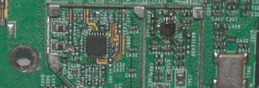
Click to zoom
Application Details
- Equipment Class
- DTS - Digital Transmission System
- Date of Grant
- Apr 13, 2004
- Application Purpose
- Original Equipment
- Date of Application
- Apr 13, 2004
- Equipment Note
- Wireless-G Ethernet Bridge with 5-Port Switch
- Frequency Range
- 2412.00000000 - 2462.00000000
- Company
- LINKSYS LLC
- Country
- United States
Documents & Files
Document Text
Text extracted from the exhibit documents filed with the FCC. Open a document above to read the original.
Users Manual
A Division of Cisco Systems, Inc. ® Model No. Ethernet Bridge Wireless-G WET54GS5 User Guide WIRELESS GHz 2.4 802.11g Wireless-G Ethernet Bridge Copyright and Trademarks Specifications are subject to change without notice. Linksys is a registered trademark or trademark of Cisco Systems, Inc. and/or its affiliates in the U.S. and certain other countries. Copyright © 2004 Cisco Systems, Inc. All rights reserved. Other brands and product names are trademarks or registered trademarks of their respective holders. How to Use this Guide Your guide to the Wireless-G Ethernet Bridge has been designed to make understanding networking with the Wireless-G Ethernet Bridge easier than ever. Look for the following items when reading this guide: In addition to these symbols, there are definitions for technical terms that are presented like this: Also, each figure (diagram, screenshot, or other image) is provided with a figure number and description, like this: Figure numbers and descriptions can also be found in the “List of Figures” section in the “Table of Contents”. This exclamation point means there is a Caution or warning and is something that could damage your property or the Wireless-G Ethernet Bridge. word: definition. This checkmark means there is a Note of interest and is something you should pay special attention to while using the Wireless-G Ethernet Bridge. This question mark provides you with a reminder about something you might need to do while using the Wireless-G Ethernet Bridge. Figure 0-1: Sample Figure Description WET54GS5-UG-403011A BW Wireless-G Ethernet Bridge Table of Contents Chapter 1: Introduction1 Welcome1 What’s in this Guide?2 Chapter 2: Planning Your Wireless Network4 Network Topology4 Network Layout5 Chapter 3: Getting to Know the Wireless-G Ethernet Bridge6 The Back Panel6 The Front Panel7 Chapter 4: Connecting the Wireless-G Ethernet Bridge for Setup8 Chapter 5: Setting Up the Wireless-G Ethernet Bridge9 Chapter 6: Connecting the Wireless-G Ethernet Bridge for Network Use14 Connection to a Network Device14 Placement Options14 Chapter 7: Using the Wireless-G Ethernet Bridge Web-based Utility16 Overview16 Starting the Web-based Utility16 Setup17 Password24 Advanced Settings24 Status26 Help27 Appendix A: Troubleshooting28 Common Problems and Solutions28 Frequently Asked Questions29 Appendix B: Wireless Security32 Security Precautions32 Security Threats Facing Wireless Networks32 Appendix C: Upgrading Firmware35 Appendix D: Windows Help36 Wireless-G Ethernet Bridge Appendix E: Glossary37 Appendix F: Specifications43 Appendix G: Warranty Information45 Appendix H: Regulatory Information46 Appendix I: Contact Information48 Wireless-G Ethernet Bridge List of Figures Figure 2-1: Infrastructure Network4 Figure 2-2: Ad-Hoc Network5 Figure 2-3: Network Using Wireless Bridging5 Figure 3-1: Back Panel6 Figure 3-2: Front Panel7 Figure 4-1: Connect to the Network8 Figure 4-2: Connect the Power8 Figure 5-1: Welcome9 Figure 5-2: Connection9 Figure 5-3: List of Bridges10 Figure 5-4: Password10 Figure 5-5: Mode Settings10 Figure 5-6: Wireless Settings11 Figure 5-7: IP Settings11 Figure 5-8: Security Settings-WEP12 Figure 5-9: Security Settings-WPA-PSK12 Figure 5-10: Confirmation13 Figure 5-11: Congratulations13 Figure 6-1: Horizontal Placement14 Figure 6-2: Vertical Placement15 Figure 7-1: Password Screen16 Figure 7-2: Setup Tab17 Figure 7-3: Site Survey18 Figure 7-4: Security Settings18 Figure 7-5: WEP19 Figure 7-6: WPA Pre-Shared Key20 Figure 7-7: Log Table20 Figure 7-8: RADIUS-MD521 Figure 7-9: RADIUS-TLS22 Wireless-G Ethernet Bridge Figure 7-10: RADIUS-TTLS23 Figure 7-11: Password Tab24 Figure 7-12: Advanced Settings Tab24 Figure 7-13: Status Tab26 Figure 7-14: Help Tab27 Figure 7-15: Firmware Upgrade27 Figure C-1: Firmware Upgrade35 1 Chapter 1: Introduction Welcome Wireless-G Ethernet Bridge Chapter 1: Introduction Welcome Thank you for choosing the Wireless-G Ethernet Bridge. The versatile Wireless-G Ethernet Bridge can make any wired Ethernet-equipped device a part of your wireless network. At home, use the Bridge to connect game consoles, set-top boxes, or computers to your Wireless-G network and its shared high-speed Internet connection. In the office, convert your Ethernet-wired printer, camera, notebook or desktop into a wireless networked device. It's completely driver-free, so it works on any platform and under any operating system! Since there's no drivers to load, setup is a snap—configure the network settings through your PC's web browser, then plug it into your device and go. And physical installation is simplified by support for Power Over Ethernet. With an optional POE Adapter, you can mount the Bridge wherever you want—power and data are both supplied through the Category 5 Ethernet cable. You can also use the Wireless-G Ethernet Bridge as a kind of “cable-less cable” to connect remote areas together. Maybe Shipping is all the way across the warehouse from Receiving. Or maybe you want to set up a home office in your detached garage. With a Wireless-G Ethernet Bridge in the garage, and another one (or a Wireless-G Access Point) in the house, you're connected—no digging trenches, and no overhead wires. Let the Wireless-G Ethernet Bridge from Linksys open up exciting new possibilities for your wireless network. Use the instructions in this Guide to help you set up and connect the Bridge. These instructions should be all you need to get the most out of the Wireless-G Ethernet Bridge. Ethernet: an IEEE standard network protocol that specifies how data is placed on and retrieved from a common transmission medium. 802.11g: an IEEE wireless networking standard that specifies a maximum data transfer rate of 54Mbps, an operating frequency of 2.4GHz, and backward compatibility with 802.11b devices. 2 Chapter 1: Introduction What’s in this Guide? Wireless-G Ethernet Bridge What’s in this Guide? This user guide covers the steps for setting up and using the Wireless-G Ethernet Bridg…
Text truncated - open the document above for the full version.
Users Manual
22 Chapter 7: Using the Wireless-G Ethernet Bridge Web-based Utility Setup Wireless-G Ethernet Bridge TLS TLS is a mutual authentication method that uses digital certificates.Select TLS from the EAP Type drop-down menu. Enter the Login name of your wireless network in the User ID field. Enter the User Certificate and Root Certificate in the fields or click the Browse button to browse for it, then upload it. • EAP Type - The authentication method that your network uses. Select TLS from the drop-down menu. • User ID -Your User ID is the Login name of your wireless network. Enter the Login name of your wireless network in the User ID field. • User Certificate - Enter the user certificate you have installed to authenticate you on your wireless network or click the Browse button to browse for it. Click the Upload button to upload the certificate. • Root Certificate - Enter the root certificate you have installed to authenticate you on your wireless network or click the Browse button to browse for it. Click the Upload button to upload the certificate. Click the Apply button to save your changes. If your page doesn’t automatically refresh itself, then click the Refresh button of your web browser. Click the View Log button to view a log. Figure 7-9: RADIUS-TLS TLS (Transport Layer Security) - A mutual authentication method that uses digital certificates. EAP (Extensible Authentication Protocol) - A general authentication protocol used to control network access. Many specific authentication methods work within this framework. 23 Chapter 7: Using the Wireless-G Ethernet Bridge Web-based Utility Setup Wireless-G Ethernet Bridge TTLS TTLS is a mutual authentication method that uses digital certificates. Select TTLS from the EAP Type drop- down menu. Enter the Login name of your wireless network in the User ID field and the password in the Password field. Enter the Root Certificate in the field or click the Browse button to browse for it, then upload it. • EAP Type - The authentication method that your network uses. Select TTLS from the drop-down menu. • User ID -Your User ID is the Login name of your wireless network. Enter the Login name of your wireless network in the User ID field. • Password - This is the password used for your wireless network. Enter the password in the Password field. • Root Certificate - Enter the root certificate you have installed to authenticate you on your wireless network or click the Browse button to browse for it. Click the Upload button to upload the certificate. Click the Apply button to save your changes. If your page doesn’t automatically refresh itself, then click the Refresh button of your web browser. Click the View Log button to view a log. To save your changes, click the Apply button. Click the Cancel button to cancel your changes. Click the Help button for additional on-screen information. Figure 7-10: RADIUS-TTLS 24 Chapter 7: Using the Wireless-G Ethernet Bridge Web-based Utility Password Wireless-G Ethernet Bridge Password The Password screen, shown in Figure 7-11, lets you change the Bridge’s Password and restore the factory default settings. • Administrative Password - It is strongly recommended that you change the factory default password of the Bridge from admin to a new password that you create. All users who try to access the Bridge’s Web-based Utility will be prompted for the Bridge’s Password. The new Password must not exceed 12 characters in length and must not include any spaces. Enter the new Password a second time to confirm it. • Restore Factory Defaults - Click the Yes radio button to reset all configuration settings to their default values. If you do not want to restore the factory defaults, then keep the default setting, No. To save your changes, click the Apply button. Click the Cancel button to cancel your changes. Click the Help button for additional on-screen information. Advanced Settings Use the Advanced Settings screen, shown in Figure 7-12, to customize advanced wireless settings and clone a MAC address onto the Bridge. Wireless • Transmission Rate - The default setting is Auto. The range is from 1 to 54Mbps.The rate of data transmission should be set depending on the speed of your wireless network. You can select from a range of transmission speeds, or you can keep the default setting, Auto, to have the Bridge automatically use the fastest possible data rate and enable the Auto-Fallback feature. Auto-Fallback will negotiate the best possible connection speed between the Bridge and another wireless-equipped device. • Authentication Type - The default setting is Auto. The choices are Auto, Open, and Shared. This setting allows the Bridge to authenticate communication with the wireless devices in your network. With the Shared key setting, all wireless devices must have the same WEP keys so that the Bridge and the client can authenticate each other and start transmitting data. With the Open system setting, any device can join a network without performing any security check. Using the Auto setting, the Bridge will automatically detect Figure 7-12: Advanced Settings Tab Figure 7-11: Password Tab IMPORTANT:Any settings you have saved will be lost if the default settings are restored. 25 Chapter 7: Using the Wireless-G Ethernet Bridge Web-based Utility Advanced Settings Wireless-G Ethernet Bridge whether a wireless device uses shared key or open system authentication, and then it will transmit data using the appropriate authentication type. • RTS Threshold - This value should remain at its default setting of 2347. The range is 0-2347 bytes. Should you encounter inconsistent data flow, only minor modifications are recommended. If a network packet is smaller than the preset RTS threshold size, the RTS/CTS mechanism will not be enabled. The Router sends Request to Send (RTS) frames to a particular receiving station and negotiates the sending of a data frame. After receiving an RTS, the wireless station responds with a Clear to Send (CTS) fram…
Text truncated - open the document above for the full version.
External Photos
Page 1 CONSTRUCTION PHOTOS OF EUT Page 2
ID Label/Location Info
(Fig. 1) FCC ID: Q87-WET54GS5 FCC LABEL LOCATION The label will be permanently affixed at a conspicuous location on the device. Label
Internal Photos
Page 1 CONSTRUCTION PHOTOS OF EUT Page 2 Page 3 Page 4 Page 5 Page 6 Page 7
Operational Description
FCC ID: Q87-WET54GS5 Report No.: 930311H04 Operational Description This device is a WET54GS5 Linksys Wireless-G Ethernet Bridge with 5-Port Switch, the maximum data rate could be up to 54Mbps which OFDM technique will be applied. If the signal to noise radio is too poor which could not support 54Mbps, the 11Mbps data rate with CCK technique will be applied. The transmitter of the EUT (WET54GS5 Linksys Wireless-G Ethernet Bridge with 5- Port Switch) is powered by power adapter. The antenna type used in this product is Dipole Antenna with Reversed SMA connector. The other instruction, please have a look at the users manual.
RF Exposure Info
FCC ID: Q87-WET54GS5 Report No.: RF930311H04 1 RF EXPOSURE REPORT REPORT NO.:RF930311H04 MODEL NO.: WET54GS5 ACCORDING: FCC Guidelines for Human Exposure IEEE C95.1 APPLICANT: Cisco-Linksys, LLC ADDRESS: 121 Theory Drive Irvine, CA 92612 (USA) ISSUED BY: Advance Data Technology Corporation LAB LOCATION: No. 81-1, Lu Liao Keng, 9 Ling, Wu Lung Tsuen, Chiung Lin Hsiang, Hsin Chu Hsien, Taiwan, R.O.C. Lab Code: 200376-0 FCC ID: Q87-WET54GS5 Report No.: RF930311H04 2 RF Exposure Measurement 1. Introduction In this document, we try to prove the safety of radiation harmfulness to the human body for our product. The limit for Maximum Permissible Exposure (MPE) specified in FCC 1.1310 is followed. The Gain of the antenna used in this product is measured in a Fully Anechoic Chamber (FAC) calibrated for antenna measurement in ADT, and also the maximum total power input to the antenna is measured. Through the Friis transmission formula and the maximum gain of the antenna, we can calculate the distance, away from the product, where the limit of MPE is reached. Although the Friis transmission formula is a far field assumption, the calculated result of that is an over-prediction for near field power density. We will take that as the worst case to specify the safety range. 2. RF Exposure Limit According to FCC 1.1310: The criteria listed in the following table shall be used to evaluate the environmental impact of human exposure to radio-frequency (RF) radiation as specified in 1.1307(b) LIMITS FOR MAXIMUM PERMISSIBLE EXPOSURE (MPE) Frequency Range (MHz) Electric Field Strength (V/m) Magnetic Field Strength (A/m) Power Density (mW/cm 2 ) Average Time (minutes) (A)Limits For Occupational / Control Exposures 300-1500......F/3006 1500-100,000......56 (B)Limits For General Population / Uncontrolled Exposure 300-1500......F/15006 1500-100,000......1.030 F = Frequency in MHz FCC ID: Q87-WET54GS5 Report No.: RF930311H04 3 3. Friis Formula Friis transmission formula : Pd = (Pout*G) / (4*pi*r 2 ) where Pd = power density in mW/cm 2 Pout = output power to antenna in mW G = gain of antenna in linear scale Pi = 3.1416 R = distance between observation point and center of the radiator in cm Pd is the limit of MPE, 1 mW/cm 2 . If we know the maximum Gain of the antenna and the total power input to the antenna, through the calculation, we will know the MPE value at distance 20cm. Ref. : David K. Cheng, Field and Wave Electromagnetics, Second Edition, Page 640, Eq. (11-133). 4. EUT Operating condition The software provided by Manufacturer enabled the EUT to transmit and receive data at lowest, middle and highest channel individually. 5. Classification This device is not fixed inside the host equipment, it is connected with host through wire. So it is easy to be re-located in the place where at least 20 cm far away from the body of the user. Warning statement to the user for keeping at least 20cm or more separation distance with the antenna should be included in users manual. So, this device is classified as Mobile Device. FCC ID: Q87-WET54GS5 Report No.: RF930311H04 4 6. Test Results 6.1 Antenna Gain The maximum Gain measured in Fully Anechoic Chamber are 3.5dBi or 2.24 (numeric). 6.2 Output Power Into Antenna & RF Exposure value at distance 20cm: FOR DSSS: Channel Channel Frequency (MHz) Output Power to Antenna (mW) Power Density (mW/cm 2 ) Limit of Power Density (mW/cm 2 ) 1241250.5820.02251.0 6243751.4040.02291.0 11246251.1680.02281.0 FOR OFDM: Channel Channel Frequency (MHz) Output Power to Antenna (mW) Power Density (mW/cm 2 ) Limit of Power Density (mW/cm 2 ) 1241220.5120.00911.0 6243720.3240.00911.0 11246220.4640.00911.0
Test Report
FCC ID: Q87-WET54GS5 Report No.: RF930311H041Issued: Mar. 24, 2004 FCC TEST REPORT REPORT NO.: RF930311H04 MODEL NO.: WET54GS5 RECEIVED: Mar. 11, 2004 TESTED: Mar. 12 to 16, 2004 APPLICANT:Cisco-Linksys, LLC ADDRESS:121 Theory Drive Irvine, CA 92612 (USA) ISSUED BY:Advance Data Technology Corporation LAB LOCATION:No. 81-1, Lu Liao Keng, 9 Ling, Wu Lung Tsuen, Chiung Lin Hsiang, Hsin Chu Hsien, Taiwan, R.O.C. This test report consists of 58 pages in total. It may be duplicated completely for legal use with the approval of the applicant. It should not be reproduced except in full, without the written approval of our laboratory.. The test results in the report only apply to the tested sample. 0536 ILAC MRA FCC ID: Q87-WET54GS5 Report No.: RF930311H042Issued: Mar. 24, 2004 Table of Contents 1CERTIFICATION ........................................................................................... 4 2SUMMARY OF TEST RESULTS................................................................... 5 3GENERAL INFORMATION ........................................................................... 6 3.1GENERAL DESCRIPTION OF EUT.............................................................. 6 3.2DESCRIPTION OF TEST MODES................................................................ 7 3.3GENERAL DESCRIPTION OF APPLIED STANDARDS ............................... 7 3.4DESCRIPTION OF SUPPORT UNITS.......................................................... 8 4TEST TYPES AND RESULTS....................................................................... 9 4.1CONDUCTED EMISSION MEASUREMENT ................................................ 9 4.1.1LIMITS OF CONDUCTED EMISSION MEASUREMENT ............................. 9 4.1.2TEST INSTRUMENTS .................................................................................. 9 4.1.3TEST SETUP .............................................................................................. 10 4.1.4EUT OPERATING CONDITIONS.................................................................11 4.1.5TEST RESULTS.......................................................................................... 12 4.2RADIATED EMISSION MEASUREMENT ................................................... 14 4.2.1LIMITS OF RADIATED EMISSION MEASUREMENT ................................ 14 4.2.2TEST INSTRUMENTS ................................................................................ 15 4.2.3TEST PROCEDURES................................................................................. 16 4.2.4TEST SETUP .............................................................................................. 17 4.2.5EUT OPERATING CONDITIONS................................................................ 17 4.2.6TEST RESULTS.......................................................................................... 18 4.2.7TEST RESULTS - DSSS............................................................................. 19 4.2.8TEST RESULTS -OFDM ............................................................................. 22 4.36dB BANDWIDTH MEASUREMENT .......................................................... 25 4.3.1LIMITS OF 6dB BANDWIDTH MEASUREMENT........................................ 25 4.3.2TEST INSTRUMENTS ................................................................................ 25 4.3.3TEST PROCEDURE ................................................................................... 26 4.3.4TEST SETUP .............................................................................................. 26 4.3.5EUT OPERATING CONDITIONS................................................................ 26 4.3.6TEST RESULTS-DSSS............................................................................... 27 4.3.7TEST RESULTS-OFDM .............................................................................. 31 4.4MAXIMUM PEAK OUTPUT POWER .......................................................... 35 4.4.1LIMITS OF MAXIMUM PEAK OUTPUT POWER MEASUREMENT ........... 35 4.4.2TEST INSTRUMENTS ................................................................................ 35 4.4.3TEST PROCEDURES................................................................................. 36 FCC ID: Q87-WET54GS5 Report No.: RF930311H043Issued: Mar. 24, 2004 4.4.4TEST SETUP .............................................................................................. 36 4.4.5EUT OPERATING CONDITIONS................................................................ 36 4.4.6TEST RESULTS- DSSS.............................................................................. 37 4.4.7TEST RESULTS- OFDM ............................................................................. 37 4.5POWER SPECTRAL DENSITY MEASUREMENT...................................... 38 4.5.1LIMITS OF POWER SPECTRAL DENSITY MEASUREMENT ................... 38 4.5.2TEST INSTRUMENTS ................................................................................ 38 4.5.3TEST PROCEDURE ................................................................................... 39 4.5.4TEST SETUP .............................................................................................. 39 4.5.5EUT OPERATING CONDITIONS................................................................ 39 4.5.6TEST RESULTS-DSSS............................................................................... 40 4.5.7TEST RESULTS-OFDM .............................................................................. 44 4.6BAND EDGES MEASUREMENT ................................................................ 48 4.6.1LIMITS OF BAND EDGES MEASUREMENT ............................................. 48 4.6.2TEST INSTRUMENTS ................................................................................ 48 4.6.3TEST PROCEDURE ................................................................................... 48 4.6.4EUT OPERATING CONDITION ................................................................…
Text truncated - open the document above for the full version.
Test Report
Report No. 930311H04 1 The Measurement of Conducted Spurious Emissions CONDUCTED SPURIOUS EMISSIONS MEASUREMENT 1. LIMITS OF CONDUCTED SPURIOUS EMISSIONS EASUREMENT Below 20dB of the highest emission level of operating band (in 100KHz Resolution Bandwidth, see Section 15.247(c)). Emissions which fall in the restricted bands, as defined in Section 15.205(a), must also comply with the limits specified in Section 15.209(a) (see Section 15.205(c)). 2. TEST INSTRUMENTS Description & ManufacturerModel No.Serial No.Calibrated Until R&S SPECTRUM ANALYZERFSP40100037May. 06, 2004 High pass filter 2.4G WHK3.1/18G- 10SS SN4Jun. 12, 2004 NOTE: 1.The calibration interval of the above test instruments is 12 months and the calibrations are traceable to NML/ROC and NIST/USA. 3. TEST PROCEDURE The transmitter output was connected to the spectrum analyzer via a low lose cable. Set both RBW and VBW of spectrum analyzer to 100 kHz with suitable frequency span including 100 kHz bandwidth from band edge. The band edges was measured and recorded. Report No. 930311H04 2 4. TEST SETUP 5. EUT OPERATING CONDITIONS The software provided by client to enable the EUT under transmission condition continuously at lowest, middle and highest channel frequencies individually. EUT SPECTRUM ANALYZER Report No. 930311H04 3 TEST RESULTS – For 802.11b The spectrum plots are attached on the following 2 pages. It shows compliance with the requirement in part 15.247(C),.15.205 and 15.209. Report No. 930311H04 4 Ch1 Report No. 930311H04 5 Ch11 Report No. 930311H04 6 TEST RESULTS – For 802.11g The spectrum plots are attached on the following 2 pages. It shows compliance with the requirement in part 15.247(C),.15.205 and 15.209. Report No. 930311H04 7 Ch1 Report No. 930311H04 8 Ch11
Test Setup Photos
FCC ID: Q87-WET54GS5 Report No.: RF930311H0456Issued: Mar. 24, 2004 5 PHOTOGRAPHS OF THE TEST CONFIGURATION CONDUCTED EMISSION TEST FCC ID: Q87-WET54GS5 Report No.: RF930311H0457Issued: Mar. 24, 2004 RADIATED EMISSION TEST
Contact Information
Applicant
Po-Wen Cheng(Regulatory Compliance Manager)
Technical Contact
Advance Data Technology CorporationEric Lin
[email protected]+886 3593 5343
81-1 Luliaoken, 9th Lin, Wulung Tsuen Chiunglin · Hsinchu · Taiwan
Test Firm
Bureau Veritas CPS (H.K.) Ltd. Taoyuan BranchRichard Chen
Technical Specifications
| # | Rule Parts | Frequency Range | Power Output |
|---|---|---|---|
| 1 | 15C | 2.41 GHz - 2.46 GHz | 51.00 mW |
Other Applications from LINKSYS LLC

Q87-WDS060
Aug 11, 2020WiFi Smart Light Switch with Dimmer
Equipment Class
DTS - Digital Transmission System
Q87-03564
Jun 28, 2020Linksys Tri-Band Wireless-AC Router
Equipment Class
NII - Unlicensed National Information Infrastructure TX
Q87-03566
Jun 23, 2020Linksys Tri-Band Wireless-AC Router
Equipment Class
NII - Unlicensed National Information Infrastructure TX
Q87-03530
Apr 29, 2020Linksys MAX-STREAM AC1900+ WiFi Range Extender
Equipment Class
NII - Unlicensed National Information Infrastructure TX
Q87-08151
Mar 30, 2020Linksys Dual-Band 802.11ax Wireless Router
Equipment Class
DTS - Digital Transmission System