Q87-WET54GV2Wireless-G Ethernet Bridge
LINKSYS LLC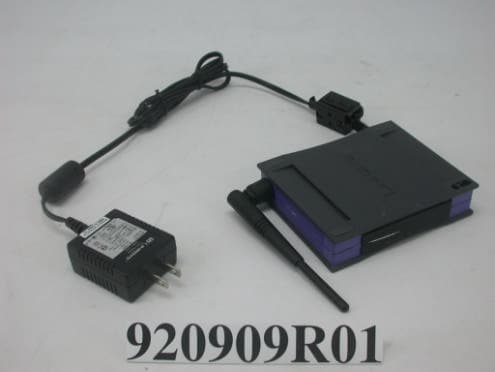
Click to zoom
Application Details
- Equipment Class
- DTS - Digital Transmission System
- Date of Grant
- Nov 09, 2003
- Application Purpose
- Original Equipment
- Date of Application
- Nov 09, 2003
- Equipment Note
- Wireless-G Ethernet Bridge
- Frequency Range
- 2412.00000000 - 2462.00000000
- Company
- LINKSYS LLC
- Country
- United States
Documents & Files
Document Text
Text extracted from the exhibit documents filed with the FCC. Open a document above to read the original.
Users Manual
Instant Wireless ® Series Use this guide to install:WET54G User Guide Wireless-G Ethernet Bridge COPYRIGHT & TRADEMARKS Specifications are subject to change without notice. Copyright © 2003 Linksys, All RightsReserved. Instant Wireless, Linksys, and the Linksys logo are registered trademarks ofLinksys Group, Inc. Microsoft, Windows, and the Windows logo are registered trade-marks of Microsoft Corporation. All other trademarks and brand names are the propertyof their respective proprietors. LIMITED WARRANTY Linksys guarantees that every Wireless-G Ethernet Bridge will be free from physicaldefects in material and workmanship for three years from the date of purchase, whenused within the limits set forth in the Specifications section of this User Guide. T h i s W a r r a n t y i s v a l i d a n d m a y b e p r o c e s s e d o n l y i n t h e c o u n t r y o f p u r c h a s e . If the product proves defective during this warranty period, go to the Linksys website at www.linksys.com for complete RMA (Return Merchandise Authorization) assistance. You can also call Linksys Technical Support in order to obtain a RMA Number. BE SURE TOHAVE YOUR PROOF OF PURCHASE AND A BARCODE FROM THE PRODUCT’S PACK-AGING ON HAND WHEN CALLING. RETURN REQUESTS CANNOT BE PROCESSEDWITHOUT PROOF OF PURCHASE. When returning a product, mark the RMA Numberclearly on the outside of the package and include a copy of your original proof of pur-chase. All customers located outside of the United States of America and Canada shallbe held responsible for shipping and handling charges.IN NO EVENT SHALL LINKSYS’S LIABILITY EXCEED THE PRICE PAID FOR THE PROD-UCT FROM DIRECT, INDIRECT, SPECIAL, INCIDENTAL, OR CONSEQUENTIAL DAM-AGES RESULTING FROM THE USE OF THE PRODUCT, ITS ACCOMPANYING SOFT-WARE, OR ITS DOCUMENTATION. LINKSYS DOES NOT OFFER REFUNDS FOR ANYPRODUCT. Linksys makes no warranty or representation, expressed, implied, or statuto-ry, with respect to its products or the contents or use of this documentation and allaccompanying software, and specifically disclaims its quality, performance, mer-chantability, or fitness for any particular purpose. Linksys reserves the right to revise orupdate its products, software, or documentation without obligation to notify any individ-ual or entity. Please direct all inquiries to:Linksys P.O. Box 18558, Irvine, CA 92623. SAFETY AND REGULATORY NOTICESFCC STATEMENTThis Wireless-G Ethernet Bridge has been tested and complies with the specifications fora Class B digital device, pursuant to Part 15 of the FCC Rules. These limits are designedto provide reasonable protection against harmful interference in a residential installation.This equipment generates, uses, and can radiate radio frequency energy and, if notinstalled and used according to the instructions, may cause harmful interference to radiocommunications. However, there is no guarantee that interference will not occur in a par-ticular installation. If this equipment does cause harmful interference to radio or televisionreception, which is found by turning the equipment off and on, the user is encouraged totry to correct the interference by one or more of the following measures:• Reorient or relocate the receiving antenna• Increase the separation between the equipment or devices• Connect the equipment to an outlet other than the receiver’s• Consult a dealer or an experienced radio/TV technician for assistance FCC Caution: Any change or modification to the product not expressly approved byLinksys could void the user’s authority to operate the device.FCC Radiation Exposure StatementThis equipment complies with FCC radiation exposure limits set forth for an uncontrolledenvironment. This equipment should be installed and operated with minimum distance20cm between the radiator and your body.• Access points with 2.4 GHz or 5 GHz integrated antenna must operate with a sepa-ration distance of at least 20 cm from all persons using the cable provided and mustnot be co-located or operating in conjunction with any other antenna or transmitter. End-users must be provided with specific operations for satisfying RF exposure compli-ance. And Linksys, LLC declare that WPC54GV1.2 (Wireless-G Ethernet Bridge ) is limited in CH1~CH11 by specified firmware controlled in U.S.A. INDUSTRY CANADA (CANADA)This Class B digital apparatus complies with Canadian ICES-003.Cet appareil numérique de la classe B est conforme à la norme NMB-003 du Canada. The use of this device in a system operating either partially or completely outdoors mayrequire the user to obtain a license for the system according to the Canadian regulations.EC DECLARATION OF CONFORMITY (EUROPE)Linksys Group declares that the Instant Wireless Series products included in the InstantWireless Series conform to the specifications listed below, following the provisions of theEMC Directive 89/336/EEC and Low Voltage Directive 73/23/EEC:• ETS 300-826, 301 489-1 General EMC requirements for Radio equipment. • EN 609 50 Safety • ETS 300-328-2 Technical requirements for Radio equipment. Note: This equipment is intended to be used in all EU and EFTA countries. Outdoor usemay be restricted to certain frequencies and/or may require a license for operation. Formore details, contact Linksys Corporate Compliance.Note: Combinations of power levels and antennas resulting in a radiated power level ofabove 100 mW are considered as not compliant with the above mentioned directive andare not allowed for use within the European community and countries that have adoptedthe European R&TTE directive 1999/5/EC and/or the CEPT recommendation Rec 70.03.For more details on legal combinations of power levels and antennas, contact LinksysCorporate Compliance.• Linksys Group vakuuttaa täten että Instant Wireless Wireless-G Ethernet Bridge tyyp- pinen laite on direktiivin 1999/5/EY, direktiivin 89/336/EEC ja direktiivin 73/23/EEColeellisten vaatimusten ja sitä koskevien näiden direktiivien muiden ehtojenmukainen. • Linksys Group …
Text truncated - open the document above for the full version.
External Photos
Page 1 CONSTRUCTION PHOTOS OF EUT
ID Label/Location Info
(Fig. 1) FCC ID: FCC LABEL LOCATION The label will be permanently affixed at a conspicuous location on the device. Label
ID Label/Location Info
WET54G v2 bottom label (3300x2549x256 jpeg)
Internal Photos
Page 2 Page 3 Page 4 Page 5 Page 6 Page 7 Page 8 Page 9 Page 10 Page 11 Page 12 Page 13 Page 14
Operational Description
FCC ID: N89-WET54GV2 ADT No. 921007H07 Operational Description This device is a Wireless-G Ethernet Bridge, the maximum data rate could be up to 54Mbps which OFDM technique will be applied. If the signal to noise radio is too poor which could not support 54Mbps, the 11Mbps data rate with CCK technique will be applied. The transmitter of the EUT (Wireless-G Ethernet Bridge) is powered by from Power Adapter. The antenna type used in this product is Dipole Antenna with Internal=UFL / External=Reversed SMA. The other instruction, please have a look at the users manual.
Test Report
Report No. 920909R01 1 The Measurement of Conducted Spurious Emissions CONDUCTED SPURIOUS EMISSIONS MEASUREMENT 1. LIMITS OF CONDUCTED SPURIOUS EMISSIONS EASUREMENT Below 20dB of the highest emission level of operating band (in 100KHz Resolution Bandwidth, see Section 15.247(c)). Emissions which fall in the restricted bands, as defined in Section 15.205(a), must also comply with the limits specified in Section 15.209(a) (see Section 15.205(c)). 2. TEST INSTRUMENTS Description & Manufacturer Model No. Serial No. Calibrated Until R&S SPECTRUM ANALYZER FSP 1093.4495.30 Dec. 19, 2003 NOTE: 1.The measurement uncertainty is less than +/- 2.6dB, which is calculated as per the NAMAS document NIS81. 2.The calibration interval of the above test instruments is 12 months and the calibrations are traceable to NML/ROC and NIST/USA. 3. TEST PROCEDURE The transmitter output was connected to the spectrum analyzer via a low lose cable. Set both RBW and VBW of spectrum analyzer to 100 kHz with suitable frequency span including 100 kHz bandwidth from band edge. The band edges was measured and recorded. Report No. 920909R01 2 4. TEST SETUP 5. EUT OPERATING CONDITIONS The software provided by client to enable the EUT under transmission condition continuously at lowest, middle and highest channel frequencies individually. EUT SPECTRUM ANALYZER Report No. 920909R01 3 TEST RESULTS – For 802.11b The spectrum plots are attached on the following 2 pages. It shows compliance with the requirement in part 15.247(C),.15.205 and 15.209. Report No. 920909R01 4 Ch1 Report No. 920909R01 5 Ch11 Report No. 920909R01 6 TEST RESULTS – For 802.11g The spectrum plots are attached on the following 2 pages. It shows compliance with the requirement in part 15.247(C),.15.205 and 15.209. Report No. 920909R01 7 Ch1 Report No. 920909R01 8 Ch11
Test Report
FCC ID: Q87-WET54GV2 Report No.: RF920909R01 56 Issued: Oct. 27, 2003 ADT No.: 920909R01 5 PHOTOGRAPHS OF THE TEST CONFIGURATION CONDUCTED EMISSION TEST FCC ID: Q87-WET54GV2 Report No.: RF920909R01 57 Issued: Oct. 27, 2003 ADT No.: 920909R01 RADIATED EMISSION TEST
Test Report
FCC ID: Q87-WET54GV2 Report No.: RF920909R01 1 Issued: Oct. 27, 2003 ADT No.: 920909R01 FCC TEST REPORT REPORT NO.: RF920909R01 MODEL NO.: WET54G V2 RECEIVED: Sep. 09, 2003 TESTED: Oct. 13 to 22, 2003 APPLICANT: Cisco-Linksys, LLC ADDRESS: 17401 Armstrong Ave. Irvine, CA 92614 ISSUED BY: Advance Data Technology Corporation LAB LOCATION: No. 81-1, Lu Liao Keng, 9 Ling, Wu Lung Tsuen, Chiung Lin Hsiang, Hsin Chu Hsien, Taiwan, R.O.C. This test report consists of 58 pages in total. It may be duplicated completely for legal use with the approval of the applicant. It should not be reproduced except in full, without the written approval of our laboratory. The client should not use it to claim product endorsement by CNLA, NVLAP or any government agencies. The test results in the report only apply to the tested sample. 0536 ILAC MRA Lab Code: 200376-0 FCC ID: Q87-WET54GV2 Report No.: RF920909R01 2 Issued: Oct. 27, 2003 ADT No.: 920909R01 Table of Contents 1 CERTIFICATION.......................................................................................................4 2 SUMMARY OF TEST RESULTS...........................................................................5 3 GENERAL INFORMATION.....................................................................................6 3.1 GENERAL DESCRIPTION OF EUT......................................................................6 3.2 DESCRIPTION OF TEST MODES........................................................................7 3.3 GENERAL DESCRIPTION OF APPLIED STANDARDS...................................7 3.4 DESCRIPTION OF SUPPORT UNITS.................................................................8 4 TEST TYPES AND RESULTS................................................................................9 4.1 CONDUCTED EMISSION MEASUREMENT......................................................9 4.1.1 LIMITS OF CONDUCTED EMISSION MEASUREMENT..................................9 4.1.2 TEST INSTRUMENTS.............................................................................................9 4.1.3 TEST SETUP..........................................................................................................10 4.1.4 EUT OPERATING CONDITIONS........................................................................11 4.1.5 TEST RESULTS.....................................................................................................12 4.2 Radiated Emission Measurement........................................................................14 4.2.1 LIMITS OF RADIATED EMISSION MEASUREMENT.....................................14 4.2.2 TEST INSTRUMENTS...........................................................................................15 4.2.3 TEST PROCEDURES...........................................................................................16 4.2.4 TEST SETUP..........................................................................................................17 4.2.5 EUT OPERATING CONDITIONS........................................................................17 4.2.6 TEST RESULTS.....................................................................................................18 4.2.7 TEST RESULTS - DSSS.......................................................................................19 4.2.8 TEST RESULTS -OFDM.......................................................................................22 4.3 6dB BANDWIDTH MEASUREMENT..................................................................25 4.3.1 LIMITS OF 6dB BANDWIDTH MEASUREMENT.............................................25 4.3.2 TEST INSTRUMENTS...........................................................................................25 4.3.3 TEST PROCEDURE..............................................................................................26 4.3.4 TEST SETUP..........................................................................................................26 4.3.5 EUT OPERATING CONDITIONS........................................................................26 4.3.6 TEST RESULTS-DSSS.........................................................................................27 4.3.7 TEST RESULTS-OFDM........................................................................................31 4.4 MAXIMUM PEAK OUTPUT POWER..................................................................35 FCC ID: Q87-WET54GV2 Report No.: RF920909R01 3 Issued: Oct. 27, 2003 ADT No.: 920909R01 4.4.1 LIMITS OF MAXIMUM PEAK OUTPUT POWER MEASUREMENT.............35 4.4.2 TEST INSTRUMENTS...........................................................................................35 4.4.3 TEST PROCEDURES...........................................................................................36 4.4.4 TEST SETUP..........................................................................................................36 4.4.5 EUT OPERATING CONDITIONS........................................................................36 4.4.6 TEST RESULTS- DSSS........................................................................................37 4.4.7 TEST RESULTS- OFDM.......................................................................................37 4.5 POWER SPECTRAL DENSITY MEASUREMENT...........................................38 4.5.1 LIMITS OF POWER SPECTRAL DENSITY MEASUREMENT......................38 4.5.2 TEST INSTRUMENTS...........................................................................................38 4.5.3 TEST PROCEDURE..............................................................................................39 4.5.4 TEST SETUP..........................................................................................................39 4.5.5 EUT OPERATING CONDITIONS........................................................................39 4.5.6 TEST RESULTS-DSSS.........................................................................................40 4.5.7 TEST…
Text truncated - open the document above for the full version.
Test Setup Photos
FCC ID: Q87-WET54GV2 Report No.: RF920909R01 56 Issued: Oct. 27, 2003 ADT No.: 920909R01 5 PHOTOGRAPHS OF THE TEST CONFIGURATION CONDUCTED EMISSION TEST FCC ID: Q87-WET54GV2 Report No.: RF920909R01 57 Issued: Oct. 27, 2003 ADT No.: 920909R01 RADIATED EMISSION TEST
Contact Information
Applicant
Po-Wen Cheng(Regulatory Compliance Manager)
Technical Contact
Advance Data Technology CorporationEric Lin
[email protected]+886 3593 5343
81-1 Luliaoken, 9th Lin, Wulung Tsuen Chiunglin · Hsinchu · Taiwan
Test Firm
Bureau Veritas CPS (H.K.) Ltd. Taoyuan BranchRichard Chen
Technical Specifications
| # | Rule Parts | Frequency Range | Power Output |
|---|---|---|---|
| 1 | 15C | 2.41 GHz - 2.46 GHz | 22.40 mW |
Other Applications from LINKSYS LLC

Q87-WDS060
Aug 11, 2020WiFi Smart Light Switch with Dimmer
Equipment Class
DTS - Digital Transmission System
Q87-03564
Jun 28, 2020Linksys Tri-Band Wireless-AC Router
Equipment Class
NII - Unlicensed National Information Infrastructure TX
Q87-03566
Jun 23, 2020Linksys Tri-Band Wireless-AC Router
Equipment Class
NII - Unlicensed National Information Infrastructure TX
Q87-03530
Apr 29, 2020Linksys MAX-STREAM AC1900+ WiFi Range Extender
Equipment Class
NII - Unlicensed National Information Infrastructure TX
Q87-08151
Mar 30, 2020Linksys Dual-Band 802.11ax Wireless Router
Equipment Class
DTS - Digital Transmission System