Q87-WMCE54AG2Wireless A+G Mini PCI Card
LINKSYS LLC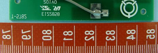
Click to zoom
Application Details
- Equipment Class
- DTS - Digital Transmission System
- Date of Grant
- Nov 01, 2004
- Application Purpose
- Original Equipment
- Date of Application
- Nov 01, 2004
- Equipment Note
- Wireless A+G Mini PCI Card
- Frequency Range
- 2412.00000000 - 2462.00000000
- Company
- LINKSYS LLC
- Country
- United States
Documents & Files
Document Text
Text extracted from the exhibit documents filed with the FCC. Open a document above to read the original.
Users Manual
chapter 1 getting to know the basics CHAPTER ONE GETTING TO KNOW THE BASICS This chapter introduces the features and components of the computer. 1-1 chapter 1 getting to know the basics Performance Features High Performance Processor The notebook PC is equipped with a powerful Intel processor of the latest sub-micron process, processor technologies, and high bus bandwidths. Advanced Graphic Engine An on-board nVidia GeForce FX Go5600 video processor with dedicated 64MB or 128MB frame buffer gives excellent graphic performance. The advanced graphic chip also incorporates a hardware-based motion-compensation engine, which gives you smooth MPEG video playback. 3D graphics capability also adds realism to PC games. Alternatively, ATI Mobility Radeo 9?00 video processor with dedicated 64MB or 128MB frame buffer may be built into the system. Large LCD Display The computer is equipped with a large 16-inch or 15.4-inch (wide aspect ratio) TFT high-resolution display panel for clear text and brilliant colors. Expandability The system offers upgradeable hard disk drive and 2 DDR SDRAM sockets for expansion, allowing the user to easily increase the storage and system capacities as the need arises. Swappable Device Bay The swappable device bay allows user to add an additional hard disk drive module for increased storage capacity. 1-2 chapter 1 getting to know the basics Built-in Multifunction Card Reader (Optional) Some system may come with a multiple card reader, which supports SD, MS, MMC Card formats. This allows user to access a wide array of portable memory devices available today. Communication Features The system provides built-in Ethernet network adapter for local network and 56K modem. Firewire (IEEE1394 / 1394a) and USB2.0 ports In addition to a full array of built-in I/O por ts, the computer offers IEEE1394 for ultra high-speed connection to high bandwidth digital video devices and USB2.0 ports to connect to any USB-based peripheral devices. Wireless LAN (Optional) or Bluetooth (Optional) The optional internal Wireless LAN module allows your notebook to connect wirelessly to other 802.11-enabled systems, devices, or network. Alternatively, the system may come with an optional Bluetooth module. TV Tuner (Optional) The optional TV Tuner module allows user to watch TV or cable programs, record TV, and capture analog video signals to the hard drive or to the recordable optical drive (optional device). 1-3 chapter 1 getting to know the basics 1-11 chapter 1 getting to know the basics Bottom View 1. Ventilation Grill The fan grill is where air is exchanged to dissipate the internal heat. Do not block this airway completely. 2. Swappable Device Bay and Latch Push the latch and pull on the drive hard case to remove the swappable device. Note: The optical drive resides in the Swappable Device Bay. Additionally, you may also purchase an optional hard drive module to be used in this bay. 1-12 chapter 1 getting to know the basics 3. Hard Disk Drive This is the system’s hard drive module. The hard disk drive stores all the system data. The hard disk drive can be upgraded to a larger capacity. (See Chapter 4 for instructions on a hard drive upgrade.) 4. Battery Pack and Battery Latch The battery pack is a built-in power source for the notebook. Slide the battery latch to release the battery pack. 1-13 chapter 1 getting to know the basics AC Adapter 1. DC-out Connector The DC-out connector docks to the power jack (DC-in) on the computer. 2. LED Lamp The LED lamp appears green when the unit is plugged into a valid AC source. 3. Adapter The adapter converts alternating current into constant DC voltage for the computer. 4. AC Plug The AC plug plugs to the AC wall outlet. Warning: Make sure you are using a standard 3-prong AC wall socket with a ground pin. If not, you may feel a slight tingling sensation on any of the computer’s metal parts such as the I/O ports. This is caused by leakage current when the AC adapter is not properly grounded (via the ground pin). However, the amount of leakage current is within the safety regulation and is not harmful to human body. 1-14 chapter 1 getting to know the basics TV Tuner / Video Capturing Module and Video / Audio Input Breakout Cable (Optional Device) Your system may a video-capturing module built-in. To record or watch TV programs, connect the external TV Tuner Module to the TV Tuner port on the notebook. If the device driver and application have not been installed to your system, you may need to do so via the factory CD-ROM disc when you first power up the notebook. S-Video in Video in Audio Left in Audio Right in Cable in / Antenna To Notebook External TV Tuner Module Alternatively, you may also use the Video / Audio Input Breakout Cable to connect to external video sources, such as a camcorder, DVD, or VCR. S-Video in Video in (Yellow) Audio Left in (White) Audio Right in (Red) To Notebook 1-15 chapter 1 getting to know the basics Remote Control (Optional Device) If your system comes with a TV Tuner / Video Capturing module, the remote control can be used to play or record TV programs. You may need to install the device driver and recording application before the remote control can be used. See the following illustration for a general description of the keys. See section elsewhere in this chapter for TV playback or record functions or see the device’s CD-ROM or help screen in the application for detailed instructions. Note: Your system may come with a different remote control. Please consult the user manual in the factory CD-ROM disc. 1-16 chapter 1 getting to know the basics How to Use the Romote, Watch TV and Record Video Clips The following is a brief guide. You need to install the card’s driver and recording application from PixelView’s installation CD-ROM disk. You need to install a utility program called TV Card or PixelView in order to use the card’s function. Connect a video source, cable, or antenna to the TV Tuner Module. …
Text truncated - open the document above for the full version.
Cover Letter(s)
Cisco-Linksys, LLC 121 Theory Drive Irvine, CA 92612 (USA) Phone: 949-823-3188 Fax: 949-823-3002 Date: October 12, 2004 FCC ID: Q87-WMCE54AG2 Federal Communications Commission Authorization and Evaluation Division Confidentiality Request Pursuant to Sections 0.457 and 0.459 of the Commission’s Rules, the Applicant hereby requests confidential treatment of information accompanying this Application as outlined below: Schematics Block Diagram The above materials contain trade secrets and proprietary information not customarily released to the public. The public disclosure of these matters might be harmful to the Applicant and provide unjustified benefits to its competitors. The Applicant understands that pursuant to Rule 0.457, disclosure of this Application and all accompanying documentation will not be made before the date of the Grant for this application. Sincerely yours, __________________________________________ Jennifer Yu / Associate Engineer Cisco-Linksys, LLC Tel.: ( 949 ) 823-3188 Fax: ( 949 ) 823-3002 [email protected]
Cover Letter(s)
Cisco-Linksys, LLC 121 Theory Drive Irvine, CA 92612 (USA) Phone: 949-823-3188 Fax: 949-823-3002 Date: October 12, 2004 FEDERAL COMMUNICATIONS COMMISSION DECLARATION OF CONFORMITY (DoC) Cisco-Linksys, LLC declares that the equipment described in this document is within the requirements of the Code of Federal Regulations listed below: Product Name: Wireless A+G Mini PCI Card Model Number: WMCE54AG2 This device complies with the limits for a Class B digital device pursuant to IEEE ANSI C63.4 and FCC Part 15 subpart B of the Rules and Regulations. The test result has been shown in the ADT test report with numbered FD930909L11A. Operation is subject to the following two conditions: 1. This device may not cause harmful interference. 2. This device must accept any interference received, including interference that may cause undesired operation. The Part 15 radio device operates on a non-interference basis with other devices operation at this frequency. Any change or modification to the product not expressly approved by Linksys could void the user’s authority to operate the device. Jennifer Yu / Associate Engineer Cisco-Linksys, LLC Tel.: ( 949 ) 823-3188 Fax: ( 949 ) 823-3002 [email protected]
External Photos
Page 1 CONSTRUCTION PHOTOS OF EUT Page 2 Page 3 Page 4
ID Label/Location Info
Page 1 Label location
ID Label/Location Info
Label Sample FCC ID: Q87-WMCE54AG2
Internal Photos
Page 5 Page 6 Page 7
Operational Description
FCC ID: Q87-WMCE54AG2 Report No.RF930909L11A Technical Description The transmitter of the EUT (Wireless A+G Mini PCI Card) is powered by host equipment via a PCMCIA interface. The antenna types used in this product are Printed and Dipole with UFL antenna connector. Under normal use condition, the user has to keep at least 20cm separation distance between radiator and the body of the user. This device is a Wireless A+G Mini PCI Card, which operates in both of the 5GHz and 2.4GHz bands and can transmitting simultaneously, the maximum data rate could be 54Mbps. For more detailed instruction, please take a look at the user’s manual. FCC 15.407(c) states: The device shall automatically discontinue transmission in case of either absence of information to transmit or operational failure. These provisions are not intended to preclude the transmission of control or signaling information or the use of repetitive codes used by certain digital technologies to complete frame or burst intervals. Applicants shall include in their application for equipment authorization a description of hoe this requirement is met” Data transmission is always initiated by software, which is then pass down through the MAC, through the digital and analog baseband, and finally to the RF chip. Several special packets (ACKs, CTS, PSPoll, etc...) are initiated by the MAC. There are the only ways the digital baseband portion will turn on the RF transmitter, which it then turns off at the end of the packet. Therefore, the transmitter will be on only while one of the aforementioned packets are being transmitted.
RF Exposure Info
FCC ID: Q87-WMCE54AG2 Report No: SA930909L11A 1 RF EXPOSURE REPORT REPORT NO.: SA930909L11A MODEL NO.: WMCE54AG2 ACCORDING: FCC Guidelines for Human Exposure IEEE C95.1 APPLICANT: Cisco-Linksys, LLC ADDRESS: 121 Theory Drive Irvine, CA 92612, U.S.A. ISSUED BY: Advance Data Technology Corporation LAB ADDRESS: 47 14th Ling, Chia Pau Tsuen, Lin Kou Hsiang 244, Taipei Hsien, Taiwan, R.O.C. TEST LOCATION: No. 19, Hwa Ya 2nd Rd., Wen Hwa Tsuen, Kwei Shan Hsiang, Taoyuan Hsien 333, Taiwan, R.O.C. FCC ID: Q87-WMCE54AG2 Report No: SA930909L11A 2 RF Exposure Measurement (Mobile Device) 1. Introduction In this document, we try to prove the safety of radiation harmfulness to the human body for our product. The limit for Maximum Permissible Exposure (MPE) specified in FCC 1.1310 is followed. The Gain of the antenna used in this product is measured in a Fully Anechoic Chamber (FAC) calibrated for antenna measurement in ADT, and also the maximum total power input to the antenna is measured. Through the Friis transmission formula and the maximum gain of the antenna, we can calculate the distance, away from the product, where the limit of MPE is reached. Although the Friis transmission formula is a far field assumption, the calculated result of that is an over-prediction for near field power density. We will take that as the worst case to specify the safety range. 2. RF Exposure Limit According to FCC 1.1310: The criteria listed in the following table shall be used to evaluate the environmental impact of human exposure to radio-frequency (RF) radiation as specified in 1.1307(b) LIMITS FOR MAXIMUM PERMISSIBLE EXPOSURE (MPE) Frequency Range (MHz) Electric Field Strength (V/m) Magnetic Field Strength (A/m) Power Density (mW/cm 2 ) Average Time (minutes) (A)Limits For Occupational / Control Exposures 300-1500......F/3006 1500-100,000......56 (B)Limits For General Population / Uncontrolled Exposure 300-1500......F/15006 1500-100,000......1.030 F = Frequency in MHz FCC ID: Q87-WMCE54AG2 Report No: SA930909L11A 3 3. Friis Formula Friis transmission formula : Pd = (Pout*G) / (4*pi*r 2 ) where Pd = power density in mW/cm 2 Pout = output power to antenna in mW G = gain of antenna in linear scale Pi = 3.1416 R = distance between observation point and center of the radiator in cm If we know the maximum Gain of the antenna and the total power input to the antenna, through the calculation, we will know the MPE value at distance 20cm. Ref. : David K. Cheng, Field and Wave Electromagnetics, Second Edition, Page 640, Eq. (11-133). 4 EUT Operating condition The software provided by Manufacturer enabled the EUT to transmit and receive data at lowest, middle and highest channel individually. 5. Classification This device is not fixed inside the host equipment, it is connected with host through wire. So it is easy to be re-located in the place where at least 20cm far away from the body of the user. Warning statement to the user for keeping at least 20cm or more separation distance with the antenna should be included in users manual. So, this device is classified as Mobile Device. FCC ID: Q87-WMCE54AG2 Report No: SA930909L11A 4 6 Test Results 6.1 Antenna Gain The maximum Gain measured in Fully Anechoic Chamber are 4.0dBi or 2.511 (numeric) for 2.4GHz, 5.0dBi or 3.162 (numeric) for 5.0GHz. 6.2 Output Power Into Antenna & RF Exposure Distance: For 2.4GHz Band: Channel Channel Frequency (MHz) Output Power to Antenna (mW) Power Density (mW/cm 2 ) Limit of Power Density (mW/cm 2 ) 1241239.8110.01991.0 6243740.7380.02041.0 11246241.6870.02081.0 For 5.0GHz Band: Normal mode: Channel Channel Frequency (MHz) Output Power to Antenna (mW) Power Density (mW/cm 2 ) Limit of Power Density (mW/cm 2 ) 1518016.0690.0101.0 4524016.1440.0101.0 5526015.8850.0101.0 853209.0160.0061.0 9574515.9590.0101.0 12580516.1440.0101.0 Turbo mode: Channel Channel Frequency (MHz) Output Power to Antenna (mW) Power Density (mW/cm 2 ) Limit of Power Density (mW/cm 2 ) 1521015.9220.0101.0 2525015.8490.0101.0 3529015.9220.0101.0 4576016.0690.0101.0 5580015.9220.0101.0 Note: Both of the 2.4GHz and 5GHz bands can transmit simultaneously, the maximum power density value is 0.0308 mW/cm 2 , which is less than the 1mW/cm 2 limit.
Test Report
FCC ID: Q87-WMCE54AG2 Report No.: RF930909L11A1Issued: Oct. 11, 2004 Reference No.: RF930909L11 FCC TEST REPORT REPORT NO.: RF930909L11A MODEL NO.: WMCE54AG2 RECEIVED: NA TESTED: Aug. 16 ~ Aug. 19, 2004 PREPARED BY: Cisco-Linksys, LLC ADDRESS: 121 Theory Drive Irvine, CA 92612, U.S.A. ISSUED BY: Advance Data Technology Corporation LAB ADDRESS: 47 14th Ling, Chia Pau Tsuen, Lin Kou Hsiang 244, Taipei Hsien, Taiwan, R.O.C. TEST LOCATION: No. 19, Hwa Ya 2nd Rd., Wen Hwa Tsuen, Kwei Shan Hsiang, Taoyuan Hsien 333, Taiwan, R.O.C. This test report consists of 173 pages in total. It may be duplicated completely for legal use with the approval of the applicant. It should not be reproduced except in full, without the written approval of our laboratory. The client should not use it to claim product endorsement by CNLA, A2LA or any government agencies. The test results in the report only apply to the tested sample. 0528 ILAC MRA FCC ID: Q87-WMCE54AG2 Report No.: RF930909L11A2Issued: Oct. 11, 2004 Reference No.: RF930909L11 Table of Contents 1.CERTIFICATION....................................................................................................5 2.SUMMARY OF TEST RESULTS.........................................................................6 2.1 MEASUREMENT UNCERTAINTY......................................................................8 3.GENERAL INFORMATION..................................................................................9 3.1GENERAL DESCRIPTION OF EUT...................................................................9 3.2DESCRIPTION OF TEST MODES...................................................................10 3.3GENERAL DESCRIPTION OF APPLIED STANDARDS..............................11 3.4DESCRIPTION OF SUPPORT UNITS.............................................................12 3.5CONFIGURATION OF SYSTEM UNDER TEST............................................12 4.TEST TYPES AND RESULTS (FOR PART 802.11b & 802.11g).................13 4.1CONDUCTED EMISSION MEASUREMENT..................................................13 4.1.1LIMITS OF CONDUCTED EMISSION MEASUREMENT.............................13 4.1.2TEST INSTRUMENTS........................................................................................13 4.1.3TEST PROCEDURES........................................................................................14 4.1.4DEVIATION FROM TEST STANDARD............................................................14 4.1.5TEST SETUP.......................................................................................................15 4.1.6EUT OPERATING CONDITIONS.....................................................................15 4.1.7TEST RESULTS...................................................................................................16 4.2RADIATED EMISSION MEASUREMENT.......................................................22 4.2.1LIMITS OF RADIATED EMISSION MEASUREMENT...................................22 4.2.2TEST INSTRUMENTS........................................................................................23 4.2.3TEST PROCEDURES........................................................................................24 4.2.4DEVIATION FROM TEST STANDARD............................................................24 4.2.5TEST SETUP.......................................................................................................25 4.2.6EUT OPERATING CONDITIONS.....................................................................25 4.2.7TEST RESULTS...................................................................................................26 4.36dB BANDWIDTH MEASUREMENT...............................................................35 4.3.1LIMITS OF 6dB BANDWIDTH MEASUREMENT...........................................35 4.3.2TEST INSTRUMENTS........................................................................................35 4.3.3TEST PROCEDURE...........................................................................................35 4.3.4DEVIATION FROM TEST STANDARD...........................................................36 4.3.5TEST SETUP.......................................................................................................36 4.3.6EUT OPERATING CONDITIONS.....................................................................36 4.3.7TEST RESULTS...................................................................................................37 4.4MAXIMUM PEAK OUTPUT POWER...............................................................47 4.4.1LIMITS OF MAXIMUM PEAK OUTPUT POWER MEASUREMENT..........47 4.4.2INSTRUMENTS...................................................................................................47 4.4.3TEST PROCEDURES........................................................................................48 4.4.4TEST SETUP.......................................................................................................48 4.4.5EUT OPERATING CONDITIONS.....................................................................48 FCC ID: Q87-WMCE54AG2 Report No.: RF930909L11A3Issued: Oct. 11, 2004 Reference No.: RF930909L11 4.4.6TEST RESULTS...................................................................................................49 4.5POWER SPECTRAL DENSITY MEASUREMENT........................................50 4.5.1LIMITS OF POWER SPECTRAL DENSITY MEASUREMENT....................50 4.5.2TEST INSTRUMENTS........................................................................................50 4.5.3TEST PROCEDURE...........................................................................................51 4.5.4DEVIATION FROM TEST STANDARD............................................................51 4.5.5TEST SETUP.......................................................................................................51 4.5.6EUT OPERATING CONDITION..................................................................…
Text truncated - open the document above for the full version.
Test Report
FCC ID: Q87-WMCE54AG2 Report No.: RF930909L11A61Issued: Oct. 11, 2004 Reference No.: RF930909L11 CH6 FCC ID: Q87-WMCE54AG2 Report No.: RF930909L11A62Issued: Oct. 11, 2004 Reference No.: RF930909L11 4.6 BAND EDGES MEASUREMENT 4.6.1 LIMITS OF BAND EDGES MEASUREMENT Below –20dB of the highest emission level of operating band (in 100KHz Resolution Bandwidth). 4.6.2 TEST INSTRUMENTS Description & ManufacturerModel No.Serial No.Calibrated Until SPECTRUM ANALYZERFSEK30100049Aug. 12, 2005 NOTE: The calibration interval of the above test instruments is 12 months and the calibrations are traceable to NML/ROC and NIST/USA. 4.6.3 TEST PROCEDURE The transmitter output was connected to the spectrum analyzer via a low lose cable. Set both RBW and VBW of spectrum analyzer to 1MHz and 10 Hz with suitable frequency span including 100 MHz bandwidth from band edge. The band edges was measured and recorded. 4.6.4 DEVIATION FROM TEST STANDARD No deviation 4.6.5 EUT OPERATING CONDITION Same as Item 4.3.6 FCC ID: Q87-WMCE54AG2 Report No.: RF930909L11A63Issued: Oct. 11, 2004 Reference No.: RF930909L11 4.6.6 TEST RESULTS The spectrum plots are attached on the following 12 pages. D2 line indicates the highest level, and D1 line indicates the 20dB offset below D2. It shows compliance with the requirement in part 15.247(C). NOTE 1: The band edge emission plot of CCK technique on page 64 show 53.28dB delta between carrier maximum power and local maximum emission in restrict band (2.3600GHz). The emission of carrier strength list in the test result of channel 1 at the item 4.2.7 is 104.3dBuV/m, so the maximum field strength in restrict band is104.3- 53.28=51.02dBuV/m which is under 54dBuV/m limit. NOTE 2: The band edge emission plot of CCK technique on page 66 show 56.85dB delta between carrier maximum power and local maximum emission in restrict band (2.4835GHz). The emission of carrier strength list in the test result of channel 11 at the item 4.2.7 is 105.53dBuV/m, so the maximum field strength in restrict band is 105.53-56.58=48.68dBuV/m which is under 54dBuV/m limit. NOTE 3: The band edge emission plot of OFDM technique with Normal mode on page 68 show 48.09dB delta between carrier maximum power and local maximum emission in restrict band (2.3900GHz). The emission of carrier strength list in the test result of channel 1 at the item 4.2.7 is 97.86dBuV/m, so the maximum field strength in restrict band is 97.86-48.09=49.77dBuV/m which is under 54dBuV/m limit. NOTE 4: The band edge emission plot of OFDM technique with Normal mode on page 70 show 48.64dB delta between carrier maximum power and local maximum emission in restrict band (2.4835GHz). The emission of carrier strength list in the test result of channel 11 at the item 4.2.7 is 98.14dBuV/m, so the maximum field strength in restrict band is 98.14-48.64=49.50dBuV/m which is under 54dBuV/m limit. NOTE 5: The band edge emission plot of OFDM technique with Turbo mode on page 72 shows 46.93dB delta between carrier maximum power and local maximum emission in restrict band (2.3599GHz). The emission of carrier strength list in the test result of channel 6 at the item 4.2.7 is 89.14dBuV/m, so the maximum field strength in restrict band is 89.14-46.93=42.21dBuV/m which is under 54dBuV/m limit. NOTE 6: The band edge emission plot of OFDM technique with Turbo mode on page 74 shows 51.39dB delta between carrier maximum power and local maximum emission in restrict band (2.4835GHz). The emission of carrier strength list in the test result of channel 6 at the item 4.2.7 is 96.02dBuV/m, so the maximum field strength in restrict band is 96.02-51.39=44.63dBuV/m which is under 54dBuV/m limit. *(The test data is in accordance with ADT Report No.: RF930909L11.) FCC ID: Q87-WMCE54AG2 Report No.: RF930909L11A64Issued: Oct. 11, 2004 Reference No.: RF930909L11 CCK mode: FCC ID: Q87-WMCE54AG2 Report No.: RF930909L11A65Issued: Oct. 11, 2004 Reference No.: RF930909L11 FCC ID: Q87-WMCE54AG2 Report No.: RF930909L11A66Issued: Oct. 11, 2004 Reference No.: RF930909L11 FCC ID: Q87-WMCE54AG2 Report No.: RF930909L11A67Issued: Oct. 11, 2004 Reference No.: RF930909L11 FCC ID: Q87-WMCE54AG2 Report No.: RF930909L11A68Issued: Oct. 11, 2004 Reference No.: RF930909L11 OFDM mode: FCC ID: Q87-WMCE54AG2 Report No.: RF930909L11A69Issued: Oct. 11, 2004 Reference No.: RF930909L11 FCC ID: Q87-WMCE54AG2 Report No.: RF930909L11A70Issued: Oct. 11, 2004 Reference No.: RF930909L11 FCC ID: Q87-WMCE54AG2 Report No.: RF930909L11A71Issued: Oct. 11, 2004 Reference No.: RF930909L11 FCC ID: Q87-WMCE54AG2 Report No.: RF930909L11A72Issued: Oct. 11, 2004 Reference No.: RF930909L11 OFDM Turbo mode: FCC ID: Q87-WMCE54AG2 Report No.: RF930909L11A73Issued: Oct. 11, 2004 Reference No.: RF930909L11 FCC ID: Q87-WMCE54AG2 Report No.: RF930909L11A74Issued: Oct. 11, 2004 Reference No.: RF930909L11 FCC ID: Q87-WMCE54AG2 Report No.: RF930909L11A75Issued: Oct. 11, 2004 Reference No.: RF930909L11 FCC ID: Q87-WMCE54AG2 Report No.: RF930909L11A76Issued: Oct. 11, 2004 Reference No.: RF930909L11 4.7 ANTENNA REQUIREMENT 4.7.1 STANDARD APPLICABLE For intentional device, according to FCC 47 CFR Section 15.203, an intentional radiator shall be designed to ensure that no antenna other than that furnished by the responsible party shall be used with the device. And according to FCC 47 CFR Section 15.247 (b), if transmitting antennas of directional gain greater than 6dBi are used, the power shall be reduced by the amount in dB that the directional gain of the antenna exceeds 6dBi. 4.7.2 ANTENNA CONNECTED CONSTRUCTION The antenna used in this product is Dipole and printed antenna with UFL connector. The maximum Gain of the antenna is 4dBi. FCC ID: Q87-WMCE54AG2 Report No.: RF930909L11A77Issued: Oct. 11, 2004 Reference No.: RF930909L11 5. TEST TYPES AND RESULTS (FOR PART 802.11a) 5.1 CONDUCTED EMISSION MEASUREMENT 5.1.1 LIMITS OF CONDUCTED EMISSION MEASUREMENT FREQUENCY OF EMISSION (MHz)CONDUCTED LIMIT (dBμV) Quasi-peakAverage 0.15-0.5 0.5-5 5-30 66 to …
Text truncated - open the document above for the full version.
Test Report
FCC ID: Q87-WMCE54AG2 Report No.: RF930909L11A111Issued: Oct. 11, 2004 Reference No.: RF930909L11 CH 5 FCC ID: Q87-WMCE54AG2 Report No.: RF930909L11A112Issued: Oct. 11, 2004 Reference No.: RF930909L11 CH 8 FCC ID: Q87-WMCE54AG2 Report No.: RF930909L11A113Issued: Oct. 11, 2004 Reference No.: RF930909L11 CH 9 FCC ID: Q87-WMCE54AG2 Report No.: RF930909L11A114Issued: Oct. 11, 2004 Reference No.: RF930909L11 CH 12 FCC ID: Q87-WMCE54AG2 Report No.: RF930909L11A115Issued: Oct. 11, 2004 Reference No.: RF930909L11 EUTWireless A+G Mini PCI CardMODEL WMCE54AG2 MODETurbo INPUT POWER (SYSTEM) 120Vac, 60 Hz ENVIRONMENTAL CONDITIONS 24deg. C, 65%RH, 991hPa TESTED BY Match Tsui CHANNEL CHANNEL FREQUEN CY (MHz) PEAK POWER OUTPUT (mW) PEAK POWER OUTPUT (dBm) PEAK POWER LIMIT (dBm) 26dBc Occupied Bandwidth (MHz) PASS/FAIL 15210 15.922 12.0217.0054.96PASS 25250 16.069 12.0017.0050.28PASS 35290 15.922 12.0224.0047.40PASS 45760 16.069 12.0630.0052.56PASS 55800 15.922 12.0230.0052.80PASS *(The test data is in accordance with ADT Report No.: RF930909L11.) NOTE: The 26dBc Occupied Bandwidth plot, please refer to the following pages. FCC ID: Q87-WMCE54AG2 Report No.: RF930909L11A116Issued: Oct. 11, 2004 Reference No.: RF930909L11 Peak Power Output: CH 1 FCC ID: Q87-WMCE54AG2 Report No.: RF930909L11A117Issued: Oct. 11, 2004 Reference No.: RF930909L11 CH 2 FCC ID: Q87-WMCE54AG2 Report No.: RF930909L11A118Issued: Oct. 11, 2004 Reference No.: RF930909L11 CH 3 FCC ID: Q87-WMCE54AG2 Report No.: RF930909L11A119Issued: Oct. 11, 2004 Reference No.: RF930909L11 CH 4 FCC ID: Q87-WMCE54AG2 Report No.: RF930909L11A120Issued: Oct. 11, 2004 Reference No.: RF930909L11 CH 5 FCC ID: Q87-WMCE54AG2 Report No.: RF930909L11A121Issued: Oct. 11, 2004 Reference No.: RF930909L11 26dB Occupied Bandwidth: CH 1 FCC ID: Q87-WMCE54AG2 Report No.: RF930909L11A122Issued: Oct. 11, 2004 Reference No.: RF930909L11 CH 2 FCC ID: Q87-WMCE54AG2 Report No.: RF930909L11A123Issued: Oct. 11, 2004 Reference No.: RF930909L11 CH 3 FCC ID: Q87-WMCE54AG2 Report No.: RF930909L11A124Issued: Oct. 11, 2004 Reference No.: RF930909L11 CH 4 FCC ID: Q87-WMCE54AG2 Report No.: RF930909L11A125Issued: Oct. 11, 2004 Reference No.: RF930909L11 CH 5 FCC ID: Q87-WMCE54AG2 Report No.: RF930909L11A126Issued: Oct. 11, 2004 Reference No.: RF930909L11 5.4 PEAK POWER EXCURSION MEASUREMENT 5.4.1 LIMITS OF PEAK POWER EXCURSION MEASUREMENT Frequency BandLimit 5.15 – 5.25 GHz13dB 5.25 – 5.35 GHz13dB 5.725 – 5.825 GHz13dB 5.4.2 TEST INSTRUMENTS Description & ManufacturerModel No.Serial No.Calibrated Until ROHDE&SCHWARZ SPECTRUM ANALYZER FSEK30100049Aug. 12, 2005 NOTE: The calibration interval of the above test instruments is 12 months and the calibrations are traceable to NML/ROC and NIST/USA. FCC ID: Q87-WMCE54AG2 Report No.: RF930909L11A127Issued: Oct. 11, 2004 Reference No.: RF930909L11 5.4.3 TEST PROCEDURE 1. The transmitter output was connected to the spectrum analyzer. 2. Set the spectrum bandwidth span to view the entire spectrum. 3. Using peak detector and Max-hold function for Trace 1 (RB=1MHz, VB=3MHz) and 2 (RB=1MHz, VB=300KHz). 4. The largest difference between Trace 1 and Trace 2 in any 1MHz band on any frequency was recorded. 5.4.4 DEVIATION FROM TEST STANDARD No deviation 5.4.5 TEST SETUP 5.4.6 EUT OPERATING CONDITIONS The software provided by client to enable the EUT under transmission condition continuously at specific channel frequencies individually. EUT SPECTRUM FCC ID: Q87-WMCE54AG2 Report No.: RF930909L11A128Issued: Oct. 11, 2004 Reference No.: RF930909L11 5.4.7 TEST RESULTS EUT Wireless A+G Mini PCI Card MODEL WMCE54AG2 MODE Normal INPUT POWER (SYSTEM) 120Vac, 60 Hz ENVIRONMENTAL CONDITIONS 24deg. C, 65%RH, 991hPa TESTED BYMatch Tsui CHANNEL CHANNEL FREQUENCY (MHz) PEAK POWER EXCURSION (dB) PEAK to AVERAGE E…
Text truncated - open the document above for the full version.
Contact Information
Applicant
Po-Wen Cheng(Regulatory Compliance Manager)
Technical Contact
Advance Data Technology Corp.Ellis Wu
[email protected]+886-3-318-3232
No.19, Hwa Ya 2nd Rd. · Kueishan Taoyuan · Taiwan
Test Firm
Advance Data Technology CorporationStephen Chen
Technical Specifications
| # | Rule Parts | Frequency Range | Power Output |
|---|---|---|---|
| 1 | 15C | 2.41 GHz - 2.46 GHz | 42.00 mW |
Other Applications from LINKSYS LLC

Q87-WDS060
Aug 11, 2020WiFi Smart Light Switch with Dimmer
Equipment Class
DTS - Digital Transmission System
Q87-03564
Jun 28, 2020Linksys Tri-Band Wireless-AC Router
Equipment Class
NII - Unlicensed National Information Infrastructure TX
Q87-03566
Jun 23, 2020Linksys Tri-Band Wireless-AC Router
Equipment Class
NII - Unlicensed National Information Infrastructure TX
Q87-03530
Apr 29, 2020Linksys MAX-STREAM AC1900+ WiFi Range Extender
Equipment Class
NII - Unlicensed National Information Infrastructure TX
Q87-08151
Mar 30, 2020Linksys Dual-Band 802.11ax Wireless Router
Equipment Class
DTS - Digital Transmission System