Q87-WMP11V4Wireless-B PCI Adapter
LINKSYS LLC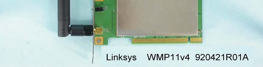
Click to zoom
Application Details
- Equipment Class
- DTS - Digital Transmission System
- Date of Grant
- Jun 26, 2003
- Application Purpose
- Original Equipment
- Date of Application
- Jun 26, 2003
- Equipment Note
- Wireless-B PCI Adapter
- Frequency Range
- 2412.00000000 - 2462.00000000
- Company
- LINKSYS LLC
- Country
- United States
Documents & Files
Document Text
Text extracted from the exhibit documents filed with the FCC. Open a document above to read the original.
Users Manual
Instant Wireless ® Series Wireless-B PCI Adapter Use this guide to install:WMP11 User Guide COPYRIGHT & TRADEMARKS Copyright © 2003 Linksys, All Rights Reserved. Instant Wireless is a trademark of Linksys.Linksys is a registered trademark of Linksys. Microsoft, Windows, and the Windows logo areregistered trademarks of Microsoft Corporation. All other trademarks and brand names are theproperty of their respective proprietors. LIMITED WARRANTY Linksys guarantees that every Instant Wireless ® Wireless-B PCI Adapter will be free from phys- ical defects in material and workmanship under normal use for one year from the date of pur-chase, when used within the limits set forth in the Specifications chapter of this User Guide. Ifthese products prove defective during this warranty period, call Linksys Technical Support inorder to obtain a Return Authorization Number. BE SURE TO HAVE YOUR PROOF OF PUR-CHASE AND A BARCODE FROM THE PRODUCT'S PACKAGING ON HAND WHEN CALLING.RETURN REQUESTS CANNOT BE PROCESSED WITHOUT PROOF OF PURCHASE. Whenreturning a product, mark the Return Authorization Number clearly on the outside of the pack-age and include a copy of your original proof of purchase. All customers located outside of theUnited States of America and Canada shall be held responsible for shipping and handlingcharges.IN NO EVENT SHALL LINKSYS’S LIABILITY EXCEED THE PRICE PAID FOR THE PRODUCTFROM DIRECT, INDIRECT, SPECIAL, INCIDENTAL, OR CONSEQUENTIAL DAMAGESRESULTING FROM THE USE OF THE PRODUCT, ITS ACCOMPANYING SOFTWARE, OR ITSDOCUMENTATION. LINKSYS DOES NOT OFFER REFUNDS FOR ANY PRODUCT. Linksysmakes no warranty or representation, expressed, implied, or statutory, with respect to its prod-ucts or the contents or use of this documentation and all accompanying software, and specif-ically disclaims its quality, performance, merchantability, or fitness for any particular purpose.Linksys reserves the right to revise or update its products, software, or documentation withoutobligation to notify any individual or entity. Please direct all inquiries to:Linksys P.O. Box 18558, Irvine, CA 92623. FCC STATEMENTThis Instant Wireless ® Wireless-B PCI Adapter has been tested and complies with the specifi- cations for a Class B digital device, pursuant to Part 15 of the FCC Rules. These limits aredesigned to provide reasonable protection against harmful interference in a residential installa-tion. This equipment generates, uses, and can radiate radio frequency energy and, if not installedand used according to the instructions, may cause harmful interference to radio communications.However, there is no guarantee that interference will not occur in a particular installation. If thisequipment does cause harmful interference to radio or television reception, which is found byturning the equipment off and on, the user is encouraged to try to correct the interference by oneor more of the following measures:• Reorient or relocate the receiving antenna• Increase the separation between the equipment or devices• Connect the equipment to an outlet other than the receiver’s• Consult a dealer or an experienced radio/TV technician for assistanceFCC Caution: Any changes or modifications nor expressly approved by the party responsiblefor compliance could void the user's authority to operate this equipment.This device complies with Part 15 of the FCC Rules. Operation is subject to the following twoconditions: (1) This device may not cause harmful interference, and (2) This device mustaccept any interference received, including interference that may cause undesired operation.FCC RF Radiation Exposure StatementThis device and its antenna(s) must operate with a separation distance of at least 20 cm fromall persons and must not be co-located or operating in conjunction with any other antenna ortransmitter. End-users must be provided with specific operations for satisfying RF exposurecompliance. WMP11-v4-UG-30530A KL Wireless-B PCI AdapterTable of ContentsChapter 1: Introduction 1 The Wireless-B PCI Adapter 1 Features 1 Chapter 2: Planning Your Wireless Network 2 Network Topology 2 Ad-Hoc versus Infrastructure Mode 2 Chapter 3: Getting to Know the Wireless-B PCI Adapter 4 The Wireless-B PCI Adapter’s Port and LEDs 4 Chapter 4: Hardware and Driver Installation andConfiguration for Windows XP 5 Overview 5 Hardware Installation for Windows XP 5 Driver Installation for Windows XP 6 Windows XP Wireless Zero Configuration 9 Chapter 5: Software Installation and Configurationfor Windows 98SE, Me, and 2000 11 Chapter 6: Hardware Installation for Windows 98SE, Me, and 2000 16 Hardware Detection for Windows 98SE, Me, and 2000 17 Chapter 7: Using the WLAN Monitor forWindows 98SE, Me, and 2000 18 Overview 18 Starting the WLAN Monitor 18 Link Information 19 Site Survey 20 Profiles 22 Creating a New Profile 24 Instant Wireless ® Series EC DECLARATION OF CONFORMITY (EUROPE)Linksys Group declares that the Instant Wireless ® Series products included in the Instant Wireless ® Series conform to the specifications listed below, following the provisions of the EMC Directive 89/336/EEC and Low Voltage Directive 73/23/EEC:• ETS 300-826, 301 489-1 General EMC requirements for Radio equipment. • EN 609 50 Safety • ETS 300-328-2 Technical requirements for Radio equipment. Note: This equipment is intended to be used in all EU and EFTA countries. Outdoor use maybe restricted to certain frequencies and/or may require a license for operation. For moredetails, contact Linksys Corporate Compliance.Note: Combinations of power levels and antennas resulting in a radiated power level ofabove 100 mW are considered as not compliant with the above mentioned directive and arenot allowed for use within the European community and countries that have adopted theEuropean R&TTE directive 1999/5/EC and/or the CEPT recommendation Rec 70.03. Formore details on legal combinations of power levels and antennas, contact Linksys CorporateCompliance.• Linksys Group™ vakuuttaa täten että Ins…
Text truncated - open the document above for the full version.
Users Manual
Wireless-B PCI Adapter 13 Instant Wireless ® Series 12 3. The Setup Wizard will ask you to choose a wireless mode, as shown in Figure 5-3. Click the Infrastructure Mode radio button if you want your wireless computers to network with computers on your wired network usinga wireless access point. Click the Ad-Hoc Mode radio button if you want multiple wireless computers to network directly with each other. Do not usethe Ad-Hoc mode if you want your wireless computers to communicate withcomputers on your wired network. In the SSID field, enter the SSID of your wireless network. The SSID must be identical for all devices in the network. The default setting is linksys (all lowercase). Click the Next button. Figure 5-3 • Install - Click the Install button to begin the software installation process. • User Guide - Click the User Guide button to open the PDF file of this User Guide. • Exit - Click the Exit button to exit the Setup Wizard. 1. To install the Adapter, click the Install button on the Welcome screen. 2. After reading the License Agreement , shown in Figure 5-2, click the Next button if you agree, or click the Cancel button to end the installation. Figure 5-2 Wireless-B PCI Adapter 15 Instant Wireless ® Series 14 6. After the files have been successfully copied, the screen in Figure 5-6 will appear. Click the Finish button. Proceed to “Chapter 6: Hardware Installation for Windows 98SE, Me, and 2000.” Figure 5-6 4. If you chose Infrastructure Mode, go to Step 5 now. If you chose Ad-Hoc Mode , , as shown in Figure 5-4, select the correct operating channel for your network. The channel you choose should match the channel set on the otherdevices in your wireless network. Click the Next button, and go to Step 5 . 5. The screen shown in Figure 5-5 will ask you to review your settings before it starts to copy files. Click the Next button to save these settings, or click the Back button to change any settings. Figure 5-4Figure 5-5 Wireless-B PCI Adapter 17 Instant Wireless ® Series 16 5. Attach the external antenna to the Adapter’s antenna port, as shown in Figure 6-2. 5. Power on your desktop PC.After the Adapter has been physically connected to your computer, Windowswill detect the new hardware. Windows will begin installing the driver files in your operating system. IfWindows asks you for the original Windows CD-ROM, insert the CD-ROM,and direct Windows to the proper location for the CD-ROM (e.g., D:\ ). Congratulations! The installation of the Wireless-B PCI Adapter is complete. If you want to check the link information, search for available wireless networks, or make additional configuration changes, proceed to “Chapter 7: Using the WLAN Monitor for Windows 98SE, Me, and 2000.” Figure 6-2 Hardware Detection for Windows 98SE, Me, and 2000 Important: Make sure the antenna is positioned straight up into the air, at a 90º angle from the Adapter (see Figure 5-2). This will ensureoptimum wireless operating range and performance. Chapter 6: Hardware Installationfor Windows 98SE, Me, and 20001. Remove any CDs or disks from their drives, and turn off your desktop PC. 2. Open your PC’s case, and locate an available PCI slot on the motherboard. Check with your computer manufacturer for instructions. 3. Slide the Adapter into the PCI slot, as shown in Figure 6-1. Make sure that all of its pins are touching the slot’s contacts. You may have to apply a bit ofpressure to slide the Adapter all the way in. 4. After the Adapter is set firmly in place, secure its fastening tab to your PC’s chassis with a mounting screw. Then close your PC’s case. Make sure that you do Chapter 5 and install the software with theSetup Wizard before you install the hardware. Figure 6-1 Wireless-B PCI AdapterThe Link Information screen (Figure 7-3) shows you the settings of your cur- rent connection.TCP/IP SettingIP Address - The IP Address of the Adapter. Subnet Mask - The Subnet Mask of the Adapter. Default Gateway - The Default Gateway address of the Adapter. DNS - The DNS address of the Adapter. DHCP - The status of the DHCP client. Wireless Network StatusState - The status of the wireless network connection. SSID - The SSID of the wireless network. Network Type - The wireless mode currently in use. Transfer Rate - The data transfer rate of the current connection. Channel - The channel to which the wireless network devices are set. WEP - The status of the WEP encryption security feature. MAC - The MAC address of the wireless network’s access point. Signal Strength - The Signal Strength bar indicates signal strength, from 0 to 100%. Link Quality - The Link Quality bar indicates the quality of the wireless net- work connection, from 0 to 100%.Click the X (Close) button in the upper right corner to exit the WLAN Monitor. 19 Instant Wireless ® Series 18 Link Information Figure 7-3 Chapter 7: Using the WLAN Monitorfor Windows 98SE, Me, and 2000Use the WLAN Monitor to check the link information, search for availablewireless networks, or make additional configuration changes.After installing the Adapter, the Wireless-B PCI Adapter WLANMonitor icon will appear in your system tray. Double-click theicon (see Figure 7-1).The Link Information screen will appear, displaying the settings for your cur- rent wireless connection. To search for available wireless networks, click theSite Survey tab. To perform configuration changes, click the Profiles tab. Figure 7-1 Figure 7-2 Important for Windows XP users: Windows XP has a built-in configuration tool. Use the Windows XP Wireless Zero Configuration (in the system tray at the bottom of your screen) to configure the Adapter. See “Chapter 6: Driver Installation and Configuration forWindows XP.” Starting the WLAN MonitorOverview Wireless-B PCI AdapterConnect - To connect to one of the networks on the list, select the wireless net- work , and click the Connect button to connect. If the wireless network has WEP encryption enabled, you will see the screen shown in Figure 7-5.In the WEP drop-down …
Text truncated - open the document above for the full version.
Users Manual
Wireless-B PCI Adapter 27 Instant Wireless ® Series 26 6. The Security Settings screen (Figure 7-13) will appear. Enable or disable Wired Equivalent Privacy (WEP) encryption for your wireless network. Ifyou enable WEP, enter a Passphrase or WEP key. Click the Next button to continue or the Back button to return to the previous screen. WEP (Disabled/64-bit WEP/128-bit WEP) - If you do not want to use WEP encryption, choose Disabled . To use WEP encryption (recommended to increase network security), select 64-bit or 128-bit WEP from the drop- down menu, and enter either a Passphrase or WEP key. Passphrase - Instead of manually entering WEP keys, you can enter a Passphrase, so that a WEP key is automatically generated. It is case-sensi-tive and should not be longer than 16 alphanumeric characters. Thispassphrase must match the passphrase of your wireless network and is com-patible with other Linksys wireless products only. (If you have any non-Linksys wireless products, enter the WEP key(s) manually on those prod-ucts.) Key 1 - This WEP key must match the WEP key of your wireless network. If you are using 64-bit WEP encryption, then the key must consist of exact-ly 10 hexadecimal characters. If you are using 128-bit WEP encryption,then the key must consist of exactly 26 hexadecimal characters. Valid hexa-decimal characters are “0” to “9” and “A” to “F”. Figure 7-13 5. The Network Setting screen (Figure 7-12) will appear. If your network has a DHCP server, click the radio button next to Obtain an IP address automatically (DHCP) . Click the Next button to continue, or click the Back button to return to the previous screen. If your network does not have a DHCP server, click the radio button next toSpecify the IP address . Enter an IP Address , Subnet Mask , Default Gateway , and DNS appropriate for your network. Enter each address in this format: xxx.xxx.xxx.xxx (the x’s represent the numbers that make up each address). You must specify the IP Address and Subnet Mask on this screen.If you are unsure about the Default Gateway and DNS addresses, then leavethese fields alone. IP Address - This IP Address must be unique to your network. Subnet Mask - The Adapter’s Subnet Mask must be the same as your wired network’s Subnet Mask.Default Gateway - Enter the IP address of your network’s Gateway here. DNS - Enter the DNS addresses of your Ethernet (wired) network here. Click the Next button to continue or the Back button to return to the previ- ous screen. Figure 7-12 Wireless-B PCI Adapter 29 Instant Wireless ® Series 28 Appendix A: TroubleshootingThis chapter provides solutions to problems that may occur during the installa-tion and operation of the Wireless-B PCI Adapter. Read the descriptions belowto solve your problems. If you can’t find an answer here, check the Linksyswebsite at www.linksys.com. 1. The Wireless-B PCI Adapter does not work properly.• Reinsert the Adapter into the PC’s PCI slot. • For Windows 98 or Me, right-click My Computer , and select Properties . Select the Device Manager tab, and select the Adapter. You will find the Adapter if it has been installed successfully. If you see a yellow exclamationmark, the resources may be in conflict, and you must follow the steps below: • Uninstall the driver software from your PC.• Restart your PC and repeat the hardware and software installation as spec- ified in this User Guide. 2. I cannot communicate with a wired computer linked via an access point in the infrastructure configuration. • Make sure that the notebook or desktop PC is powered on.• Make sure that the Wireless-B PCI Adapter is configured with the same channel, SSID, and WEP encryption as the other computers in the infra-structure LAN. Can I run an application from a remote computer over the wireless network?This will depend on whether or not the application is designed to be used overa network. Consult the application’s user guide to determine if it supports oper-ation over a network.Can I play computer games with other members of the wireless network?Yes, as long as the game supports multiple players over a LAN (local area net-work). Refer to the game’s user guide for more information.What is the IEEE 802.11b standard?It is one of the IEEE standards for wireless networks. The 802.11b standardallows wireless networking hardware from different manufacturers to commu-nicate, provided that the hardware complies with the 802.11b standard. The Common Problems and SolutionsFrequently Asked Questions 7. The Confirm New Settings screen (Figure 7-14) willappear. If these set-tings are correct,click Ye s . If they are not, click No . 8. The Congratula-tions screen (Figure 7-15) will appear next. Click Activate new settings now to implement the new settings immediately and finish the WLAN Monitor.Click Activate new settings later to keep the current settingsactive, and return tothe Profiles screen so that you can edit yourprofile or createanother profile. You have successfully created a connection profile. Click the X (Close) button in the upper right corner to exit the WLAN Monitor. Figure 7-14 Figure 7-15 Wireless-B PCI Adapter 31 Instant Wireless ® Series 30 As the user moves on, the end node’s RF transmitter regularly checks the sys-tem to determine whether it is in touch with the original access point or whetherit should seek a new one. When a node no longer receives acknowledgmentfrom its original access point, it undertakes a new search. Upon finding a newaccess point, it then re-registers, and the communication process continues.What is ISM band?The FCC and their counterparts outside of the U.S. have set aside bandwidthfor unlicensed use in the ISM (Industrial, Scientific and Medical) band.Spectrum in the vicinity of 2.4 GHz, in particular, is being made availableworldwide. This presents a truly revolutionary opportunity to place convenienthigh-speed wireless capabilities in the hands of users around the globe. What is Spread Spectrum?Spread Spectrum technology is a wideband rad…
Text truncated - open the document above for the full version.
External Photos
Page 1 ANNEX PHOTOGRAPHS OF EUT
Internal Photos
Page 2 Page 3 Page 4 Page 5
Operational Description
FCC ID: Q87-WMP11V4 ADT No.920421R01A Operational Description The transmitter of the EUT is powered by host equipment. The antenna used in this product is Dipole antenna with SMA antenna connector. Under normal use condition, the user has to keep at least 20cm separation distance away from the radiator. The other instruction, please have a look at the users manual. DSSS Information This device is Direct Sequence Spread Spectrum, the data is mixed by pseudorandom code which is an orthogonal code. The mixed data is digital modulated by BPSK and QPSK technique depends on the data rates. The CCK coding is applied for increasing the data rate, and also the processing gain will be increased. The bit rates are 1,2,5.5,11Mbps, the symbol rates are 1,1,1.375,1.375Mbps, the chip rates are always 11Mbps. So, the Chip/symbol is 11,11,8 and 8 respectively. Although is higher bit rate, the processing gain is lower than 10, but the CCK coding used in higher bit rate will provide 2.2dB coding gain.
RF Exposure Info
FCC ID: Q87-WMP11V4 Report No: 920421R01A 1 RF EXPOSURE REPORT REPORT NO.: RF920421R01A MODEL NO.: WMP11 v4 ACCORDING: FCC Guidelines for Human Exposure IEEE C95.1 APPLICANT: Cisco-Linksys, LLC ADDRESS: 17401 Armstrong Ave. Irvine, CA 92614 ISSUED BY: Advance Data Technology Corporation LAB LOCATION: 47 14th Lin, Chiapau Tsun, Linko, Taipei, Taiwan, R.O.C. 0528 ILAC MRA Lab Code: 200102-0 FCC ID: Q87-WMP11V4 Report No: 920421R01A 2 RF Exposure Measurement (Mobile Device) 1. Introduction In this document, we try to prove the safety of radiation harmfulness to the human body for our product. The limit for Maximum Permissible Exposure (MPE) specified in FCC 1.1310 is followed. The Gain of the antenna used in this product is measured in a Fully Anechoic Chamber (FAC) calibrated for antenna measurement in ADT, and also the maximum total power input to the antenna is measured. Through the Friis transmission formula and the maximum gain of the antenna, we can calculate the distance, away from the product, where the limit of MPE is reached. Although the Friis transmission formula is a far field assumption, the calculated result of that is an over-prediction for near field power density. We will take that as the worst case to specify the safety range. 2. RF Exposure Limit According to FCC 1.1310: The criteria listed in the following table shall be used to evaluate the environmental impact of human exposure to radio-frequency (RF) radiation as specified in 1.1307(b) LIMITS FOR MAXIMUM PERMISSIBLE EXPOSURE (MPE) Frequency Range (MHz) Electric Field Strength (V/m) Magnetic Field Strength (A/m) Power Density (mW/cm 2 ) Average Time (minutes) (A)Limits For Occupational / Control Exposures 300-1500......F/3006 1500-100,000......56 (B)Limits For General Population / Uncontrolled Exposure 300-1500......F/15006 1500-100,000......1.030 F = Frequency in MHz FCC ID: Q87-WMP11V4 Report No: 920421R01A 3 3. Friis Formula Friis transmission formula : Pd = (Pout*G) / (4*pi*r 2 ) where Pd = power density in mW/cm 2 Pout = output power to antenna in mW G = gain of antenna in linear scale Pi = 3.1416 R = distance between observation point and center of the radiator in cm If we know the maximum Gain of the antenna and the total power input to the antenna, through the calculation, we will know the MPE value at distance r. Ref. : David K. Cheng, Field and Wave Electromagnetics, Second Edition, Page 640, Eq. (11-133). 4 EUT Operating condition The software provided by Manufacturer enabled the EUT to transmit and receive data at lowest, middle and highest channel individually. 5. Classification This modular is specified to be installed in access point or router which is connected with host through wire. So it is easy to be re-located in the place where at least 20cm far away from the body of the user. Warning statement to the user for keeping at least 20cm or more separation distance with the antenna should be included in users manual. So, this device is classified as Mobile Device. FCC ID: Q87-WMP11V4 Report No: 920421R01A 4 6 Test Results 6.1 Antenna Gain The maximum Gain measured in Fully Anechoic Chamber are 5dBi or 3.162 (numeric). 6.2 Output Power Into Antenna & RF Exposure value at distance 20cm: Channel Channel Frequency (MHz) Output Power to Antenna (mW) Power Density (mW/cm 2 ) Limit of Power Density (mW/cm 2 ) 1241296.610.06081.0 6243798.630.06201.0 11246296.610.06081.0
Test Report
FCC ID: Q87-WMP11V4 Report No.: RF920421R01A1Issued: May 10, 2003 FCC TEST REPORT REPORT NO.: RF920421R01A MODEL NO.: WMP11 v4 RECEIVED: Apr. 21, 2003 TESTED: Apr. 25 ~ Apr. 30, 2003 APPLICANT: Cisco-Linksys, LLC ADDRESS: 17401 Armstrong Ave. Irvine, CA 92614 ISSUED BY: Advance Data Technology Corporation LAB LOCATION: 47 14th Lin, Chiapau Tsun, Linko, Taipei, Taiwan, R.O.C. This test report consists of 49 pages in total. It may be duplicated completely for legal use with the approval of the applicant. It should not be reproduced except in full, without the written approval of our laboratory. The client should not use it to claim product endorsement by CNLA, NVLAP or any government agencies. The test results in the report only apply to the tested sample. 0528 ILAC MRA Lab Code: 200102-0 FCC ID: Q87-WMP11V4 Report No.: RF920421R01A2Issued: May 10, 2003 Table of Contents 1CERTIFICATION ........................................................................................... 4 2SUMMARY OF TEST RESULTS................................................................... 5 3GENERAL INFORMATION ........................................................................... 6 3.1GENERAL DESCRIPTION OF EUT.............................................................. 6 3.2DESCRIPTION OF TEST MODES................................................................ 7 3.3GENERAL DESCRIPTION OF APPLIED STANDARDS ............................... 7 3.4DESCRIPTION OF SUPPORT UNITS .......................................................... 8 4TEST TYPES AND RESULTS....................................................................... 9 4.1CONDUCTED EMISSION MEASUREMENT ................................................ 9 4.1.1LIMITS OF CONDUCTED EMISSION MEASUREMENT.............................. 9 4.1.2TEST INSTRUMENTS .................................................................................. 9 4.1.3TEST PROCEDURES................................................................................. 10 4.1.4TEST SETUP .............................................................................................. 10 4.1.5EUT OPERATING CONDITIONS.................................................................11 4.1.6TEST RESULTS.......................................................................................... 12 4.2RADIATED EMISSION MEASUREMENT ................................................... 18 4.2.1LIMITS OF RADIATED EMISSION MEASUREMENT................................. 18 4.2.2TEST INSTRUMENTS ................................................................................ 19 4.2.3TEST PROCEDURES................................................................................. 20 4.2.4TEST SETUP .............................................................................................. 21 4.2.5EUT OPERATING CONDITIONS................................................................ 21 4.2.6TEST RESULTS.......................................................................................... 22 4.36dB BANDWIDTH MEASUREMENT .......................................................... 27 4.3.1LIMITS OF 6dB BANDWIDTH MEASUREMENT ........................................ 27 4.3.2TEST INSTRUMENTS ................................................................................ 27 4.3.3TEST PROCEDURE ................................................................................... 28 4.3.4TEST SETUP .............................................................................................. 28 4.3.5EUT OPERATING CONDITIONS................................................................ 28 4.3.6TEST RESULTS.......................................................................................... 29 4.4MAXIMUM PEAK OUTPUT POWER .......................................................... 33 4.4.1LIMITS OF MAXIMUM PEAK OUTPUT POWER MEASUREMENT ........... 33 4.4.2TEST INSTRUMENTS ................................................................................ 33 4.4.3TEST PROCEDURES................................................................................. 34 4.4.4TEST SETUP .............................................................................................. 34 4.4.5EUT OPERATING CONDITIONS................................................................ 34 FCC ID: Q87-WMP11V4 Report No.: RF920421R01A3Issued: May 10, 2003 4.4.6TEST RESULTS.......................................................................................... 35 4.5POWER SPECTRAL DENSITY MEASUREMENT...................................... 36 4.5.1LIMITS OF POWER SPECTRAL DENSITY MEASUREMENT ................... 36 4.5.2TEST INSTRUMENTS ................................................................................ 36 4.5.3TEST PROCEDURE ................................................................................... 37 4.5.4TEST SETUP .............................................................................................. 37 4.5.5EUT OPERATING CONDITIONS................................................................ 37 4.5.6TEST RESULTS.......................................................................................... 38 4.6BAND EDGES MEASUREMENT ................................................................ 42 4.6.1LIMITS OF BAND EDGES MEASUREMENT ............................................. 42 4.6.2TEST INSTRUMENTS ................................................................................ 42 4.6.3TEST PROCEDURE ................................................................................... 42 4.6.4EUT OPERATING CONDITION .................................................................. 42 4.6.5TEST RESULTS.......................................................................................... 43 4.7ANTENNA REQUIREMENT........................................................................ 46 4.7.1STANDARD APPLICABLE .......................................................................... 46…
Text truncated - open the document above for the full version.
Test Setup Photos
FCC ID: Q87-WMP11V4 Report No.: RF920421R01A47Issued: May 10, 2003 5 PHOTOGRAPHS OF THE TEST CONFIGURATION CONDUCTED EMISSION TEST FCC ID: Q87-WMP11V4 Report No.: RF920421R01A48Issued: May 10, 2003 RADIATED EMISSION TEST
Contact Information
Applicant
Po-Wen Cheng(Regulatory Compliance Manager)
Technical Contact
Advance Data Technology CorporationEllis Wu
[email protected]+886 3 327 0910
13-1, Lane 19, WenShan 3rd St · Taoyuan · Taiwan
Test Firm
Bureau Veritas CPS (H.K.) Ltd. Taoyuan BranchRichard Chen
Technical Specifications
| # | Rule Parts | Frequency Range | Power Output |
|---|---|---|---|
| 1 | 15C | 2.41 GHz - 2.46 GHz | 99.00 mW |
Other Applications from LINKSYS LLC

Q87-WDS060
Aug 11, 2020WiFi Smart Light Switch with Dimmer
Equipment Class
DTS - Digital Transmission System
Q87-03564
Jun 28, 2020Linksys Tri-Band Wireless-AC Router
Equipment Class
NII - Unlicensed National Information Infrastructure TX
Q87-03566
Jun 23, 2020Linksys Tri-Band Wireless-AC Router
Equipment Class
NII - Unlicensed National Information Infrastructure TX
Q87-03530
Apr 29, 2020Linksys MAX-STREAM AC1900+ WiFi Range Extender
Equipment Class
NII - Unlicensed National Information Infrastructure TX
Q87-08151
Mar 30, 2020Linksys Dual-Band 802.11ax Wireless Router
Equipment Class
DTS - Digital Transmission System