Q87-WMP54GV4Wireless-G PCI Adapter
LINKSYS LLC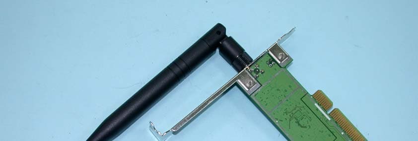
Click to zoom
Application Details
- Equipment Class
- DTS - Digital Transmission System
- Date of Grant
- Apr 13, 2004
- Application Purpose
- Original Equipment
- Date of Application
- Apr 13, 2004
- Equipment Note
- Wireless-G PCI Adapter
- Frequency Range
- 2412.00000000 - 2462.00000000
- Company
- LINKSYS LLC
- Country
- United States
Documents & Files
Document Text
Text extracted from the exhibit documents filed with the FCC. Open a document above to read the original.
Users Manual
19 Chapter 6: Using the Wireless Network Monitor The Site Survey Tab Wireless-G PCI Adapter The Site Survey Tab The Site Survey tab displays available networks and allows you to connect to them. The information about these networks are displayed as below: SSID - The SSID or unique name of the wireless network. CH - The channel upon which the network broadcasts. Signal - The percentage of signal strength, from 0 to 100%. Site Information SSID - The SSID or unique name of the wireless network. Wireless Mode - The mode of the wireless network currently in use. Channel - The channel to which the wireless network devices are set. Security - The status of the wireless security feature. MAC - The MAC address of the wireless network’s access point. Refresh - Click the Refresh button to perform a new search for wireless devices. Connect - To connect to one of the networks on the list, select the wireless network (by SSID), and click the Connect button. If the wireless network has WEP encryption enabled, you will need to configure WEP encryption with that network. Figure 6-4: The Site Survey Tab 20 Chapter 6: Using the Wireless Network Monitor The Profiles Tab Wireless-G PCI Adapter The Profiles Tab The Profiles screen lets you save different configuration profiles for different network setups. You can also import or export profiles. The default profile holds the initial configuration saved when you ran the Setup Wizard. Profile - Name of the connection profile. SSID - The wireless network’s unique name, as set in the connection profile. Profile Information Wireless Mode - The mode of the wireless network currently in use. Transfer Rate - The data transfer rate of the current connection. (In Auto mode, the Adapter dynamically shifts to the fastest data transfer rate possible at any given time.) Channel - The channel to which the wireless network devices are set. Security - The status of the wireless security feature. Authentication - The authentication setting for the network. Connect - To connect to a wireless network using a specific profile, select the profile, and click the Connect button. New - Click the New button to create a new profile. See the next section, “Creating a New Profile,” for detailed instructions. Edit - Select a profile, and click the Edit button to change an existing profile. Figure 6-5: The Profiles Tab 21 Chapter 6: Using the Wireless Network Monitor The Profiles Tab Wireless-G PCI Adapter Import - Click the Import button to import a profile that has been saved in another location. Select the appropriate file and click the Open button. Export - To save the profile(s) in a different location, click the Export button. Direct Windows to the appropriate folder and click the OK button. Delete - Click the Delete button to delete a profile. Click the X (Close) button in the upper right corner to exit the Wireless Network Monitor. Figure 6-7: Exporting a Profile Figure 6-6: Importing a Profile 22 Chapter 6: Using the Wireless Network Monitor Creating a New Profile Wireless-G PCI Adapter Creating a New Profile 1. On the Profiles tab, click the New button to create a new profile. 2. When the Create connection profile screen appears, enter a name for the new profile. Click OK to save the profile name or click Cancel to return to the previous screen. Figure 6-9: Create Connection Profile Figure 6-8: The Profiles Tab 23 Chapter 6: Using the Wireless Network Monitor Creating a New Profile Wireless-G PCI Adapter 3. Enter your network’s settings on the Network Settings screen, which appears next. If your network has a DHCP server (or Router), click the radio button next to Obtain an IP address automatically (DHCP) and click the Next button to continue. If your network does not have a DHCP server (or router), click the radio button next to Specify the IP address. Enter an IP Address, Subnet Mask, Default Gateway, and DNS appropriate for your network. Enter each address in this format: xxx.xxx.xxx.xxx (the x’s represent the numbers that make up each address). You must specify the IP Address and Subnet Mask on this screen. If you are unsure about the Default Gateway and DNS addresses, then leave these fields alone. IP Address - This IP Address must be unique to your network. Subnet Mask - The Adapter’s Subnet Mask must be the same as your wired network’s Subnet Mask. Default Gateway - Enter the IP address of your network’s Gateway here. DNS - Enter the DNS addresses of your network here. Click the Next button to continue or the Cancel button to return to the previous screen. 4. The Wireless Mode screen shows a choice of two wireless modes. Click the Infrastructure Mode radio button if you want your wireless computers to communicate with computers on your wired network via a wireless access point, and continue to Step 6. Click the Ad-Hoc Mode radio button if you want multiple wireless computers to communicate directly with each other. Click the Next button to continue or the Back button to return to the previous screen. Infrastructure Mode - This mode allows wireless and wired networks to communicate through an access point. Continue to Step 6 if selecting this mode. Ad-Hoc Mode - This mode allows wireless-equipped computers to communicate directly with each other. No access point is used. SSID - The SSID is the unique name shared among all devices in your wireless network. The SSID must be identical for all devices in the wireless network. It is case-sensitive and must not exceed 32 alphanumeric characters, which can be any keyboard character. Figure 6-11: Profiles - Wireless Mode Figure 6-10: Profiles - Network Settings 24 Chapter 6: Using the Wireless Network Monitor Creating a New Profile Wireless-G PCI Adapter 5. The Ad-Hoc Mode Settings screen, for those who chose an Ad-hoc network, will appear next. Select the correct operating channel for your network from the Channel drop-down menu. Then, select the Network Mode from the drop-down menu. Click the Next button to continue or click the …
Text truncated - open the document above for the full version.
Users Manual
A Division of Cisco Systems, Inc. ® Model No. PCI Adapter Wireless-G WMP54Gv4 User Guide WIRELESS GHz 2.4 802.11g Wireless-G PCI Adapter Copyright and Trademarks Specifications are subject to change without notice. Linksys is a registered trademark or trademark of Cisco Systems, Inc. and/or its affiliates in the U.S. and certain other countries. Copyright © 2004 Cisco Systems, Inc. All rights reserved. Other brands and product names are trademarks or registered trademarks of their respective holders. How to Use This User Guide This User Guide has been designed to make understanding networking with the Wireless-G PCI Adapter easier than ever. Look for the following items when reading this User Guide: In addition to these symbols, there are definitions for technical terms that are presented like this: Also, each figure (diagram, screenshot, or other image) is provided with a figure number and description, like this: Figure numbers and descriptions can also be found in the “List of Figures” section in the “Table of Contents”. This exclamation point means there is a caution or warning and is something that could damage your property or the Wireless-G PCI Adapter. This checkmark means there is a note of interest and is something you should pay special attention to while using the Wireless-G PCI Adapter. This question mark provides you with a reminder about something you might need to do while using the Wireless-G PCI Adapter. word: definition. Figure 0-1: Sample Figure Description WMP54G v4-UG-40412NC KL Wireless-G PCI Adapter with SpeedBooster Table of Contents Chapter 1: Introduction1 Welcome1 What’s in this Guide?2 Chapter 2: Planning your Wireless Network4 Network Topology4 Roaming4 Network Layout5 Chapter 3: Software Installation and Configuration for Windows 2000, 98, and ME 6 Chapter 4: Connecting the PCI Adapter11 Chapter 5: Driver Installation for Windows XP13 Windows XP Wireless Zero Configuration14 Chapter 6: Using the Wireless Network Monitor16 Overview16 Accessing the Wireless Network Monitor16 The Link Information Tab16 The Site Survey Tab19 The Profiles Tab20 Creating a New Profile22 Appendix A: Troubleshooting26 Common Problems and Solutions26 Frequently Asked Questions27 Appendix B: Wireless Security30 Security Precautions30 Security Threats Facing Wireless Networks30 Appendix C: Windows Help33 Appendix D: Glossary34 Appendix E: Specifications38 Appendix F: Warranty Information39 Appendix G: Regulatory Information40 Appendix H: Contact Information42 Wireless-G PCI Adapter with SpeedBooster List of Figures Figure 3-1: The Setup Wizard’s Welcome Screen6 Figure 3-2: The License Agreement Screen7 Figure 3-3: The Wireless Mode Screen7 Figure 3-4: The Ad-Hoc Mode Settings Screen8 Figure 3-5: The Wireless Security Screen8 Figure 3-6: The Check Settings Screen9 Figure 3-7: The Windows Digital Signature Screen9 Figure 3-8: The Congratulations Screen10 Figure 4-1: Your Computer’s PCI slot with Adapter installed11 Figure 4-2: Proper Positioning of the Antenna12 Figure 5-1: XP Setup Welcome Screen13 Figure 5-2: Windows logo testing screen13 Figure 5-3: New Hardware Found screen13 Figure 5-4: Windows XP Wireless Zero Configuration icon14 Figure 5-5: Network Connection - No WEP14 Figure 5-6: Network Connection - WEP15 Figure 5-7: Optional Settings15 Figure 6-1: The Link Information Tab16 Figure 6-2: The Link Information Tab - More Information17 Figure 6-3: The Link Information Tab - Statistics18 Figure 6-4: The Site Survey Tab19 Figure 6-5: The Profiles Tab20 Figure 6-6: Importing a Profile21 Figure 6-7: Exporting a Profile21 Figure 6-8: The Profiles Tab22 Figure 6-9: Create Connection Profile22 Figure 6-10: Profiles - Network Settings23 Figure 6-11: Profiles - Wireless Mode23 Figure 6-12: Profiles - Ad-Hoc Settings24 Figure 6-13: Profiles - Security Settings24 Wireless-G PCI Adapter with SpeedBooster Figure 6-14: Profiles - Confirm New Settings25 Figure 6-15: Profiles - Congratulations25 1 Chapter 1: Introduction Welcome Wireless-G PCI Adapter Chapter 1: Introduction Welcome Thank you for choosing the Wireless-G PCI Adapter. With this Adapter, your wireless networking experience will be faster and easier than ever. Like all wireless products, the Adapter allows for greater range and mobility within your wireless network. This adapter communicates over the 54Mbps 802.11g wireless standard, which is almost five times faster than 802.11b. But since they share the same 2.4GHz radio band, the Adapter can also communicate with the widely used 11Mbps 802.11b standard. PCs equipped with wireless cards and adapters can communicate without cumbersome cables. By sharing the same wireless settings, within their transmission radius, they form a wireless network. The included Setup Wizard will walk you through configuring the adapter to your network's settings, step by step. Then just slide it into your computer's PCI Card slot and enjoy network access with the freedom of wireless. Once you're connected, you can keep in touch with your e-mail, access the Internet, and share files and other resources such as printers and network storage with other computers on the network. At home, you can surf the web or use instant messaging to chat with friends while sitting out on the patio. Your wireless connection is protected by the new, industrial-strength security of Wireless Protected Access (WPA). Get connected to current-standard 802.11b networks today, and be prepared for the future with the Wireless-G PCI Adapter from Linksys. 802.11b: an IEEE wireless networking standard that specifies a maximum data transfer rate of 11Mbps and an operating frequency of 2.4GHz adapter: a device that adds network functionality to your PC. network: a series of computers or devices connected for the purpose of data sharing, storage, and/or transmission between users. 802.11g an IEEE wireless networking standard that specifies a maximum data transfer rate of 54Mbps, an operating frequency of 2.4GHz, and backward compatibility…
Text truncated - open the document above for the full version.
External Photos
Page 1 CONSTRUCTION PHOTOS OF EUT Page 2 Page 3 Page 4
Internal Photos
Page 5 Page 6 Page 7
Operational Description
FCC ID: Q87-WMP54GV4 Report No.RF930308R01 Operational Description This device is a Wireless-G PCI Adapter which operates in the 2.4GHz frequency spectrum with throughput of up to 54Mbps which OFDM technique will be applied. If the signal to noise radio is too poor which could not support 54Mbps, the 11Mbps data rate with CCK technique will be applied. The transmitter of the EUT is powered by host equipment. The antenna is Dipole antenna with reversed SMA connector. The other instruction, please have a look at the users manual.
RF Exposure Info
FCC ID: Q87-WMP54GV4 Report No: SA930308R01 1 RF EXPOSURE REPORT REPORT NO.: SA930308R01 MODEL NO.: WMP54Gv4 ACCORDING: FCC Guidelines for Human Exposure IEEE C95.1 APPLICANT: Cisco-Linksys, LLC ADDRESS: 121 Theory Drive, Irvine, CA 92612 (USA) ISSUED BY: Advance Data Technology Corporation LAB LOCATION: 47 14th Lin, Chiapau Tsun, Linko, Taipei, Taiwan, R.O.C. FCC ID: Q87-WMP54GV4 Report No: SA930308R01 2 RF Exposure Measurement (Mobile Device) 1. Introduction In this document, we try to prove the safety of radiation harmfulness to the human body for our product. The limit for Maximum Permissible Exposure (MPE) specified in FCC 1.1310 is followed. The Gain of the antenna used in this product is measured in a Fully Anechoic Chamber (FAC) calibrated for antenna measurement in ADT, and also the maximum total power input to the antenna is measured. Through the Friis transmission formula and the maximum gain of the antenna, we can calculate the distance, away from the product, where the limit of MPE is reached. Although the Friis transmission formula is a far field assumption, the calculated result of that is an over-prediction for near field power density. We will take that as the worst case to specify the safety range. 2. RF Exposure Limit According to FCC 1.1310: The criteria listed in the following table shall be used to evaluate the environmental impact of human exposure to radio-frequency (RF) radiation as specified in 1.1307(b) LIMITS FOR MAXIMUM PERMISSIBLE EXPOSURE (MPE) Frequency Range (MHz) Electric Field Strength (V/m) Magnetic Field Strength (A/m) Power Density (mW/cm 2 ) Average Time (minutes) (A)Limits For Occupational / Control Exposures 300-1500......F/3006 1500-100,000......56 (B)Limits For General Population / Uncontrolled Exposure 300-1500......F/15006 1500-100,000......1.030 F = Frequency in MHz FCC ID: Q87-WMP54GV4 Report No: SA930308R01 3 3. Friis Formula Friis transmission formula : Pd = (Pout*G) / (4*pi*r 2 ) where Pd = power density in mW/cm 2 Pout = output power to antenna in mW G = gain of antenna in linear scale Pi = 3.1416 R = distance between observation point and center of the radiator in cm If we know the maximum Gain of the antenna and the total power input to the antenna, through the calculation, we will know the MPE value at distance 20cm. Ref. : David K. Cheng, Field and Wave Electromagnetics, Second Edition, Page 640, Eq. (11-133). 4 EUT Operating condition The software provided by Manufacturer enabled the EUT to transmit and receive data at lowest, middle and highest channel individually. 5. Classification The antenna of the product, under normal use condition, is at least 20cm away from the body of the user. Warning statement for keeping 20cm-separation distance and the prohibition of operating next to a person has been printed on the user’s manual. So, this product is classified as the Mobile Device. FCC ID: Q87-WMP54GV4 Report No: SA930308R01 4 6 Test Results 6.1 Antenna Gain The maximum Gain measured in Fully Anechoic Chamber is 5dBi or 3.162 (numeric). 6.2 Output Power Into Antenna & RF Exposure Distance : For Part 802.11b (CCK technique): Channel Channel Frequency (MHz) Output Power to Antenna (mW) Power Density (mW/cm 2 ) Limit of Power Density (mW/cm 2 ) 1241219.9070.0131.0 6243720.0910.0131.0 11246219.4090.0121.0 For Part 802.11g (OFDM technique): Channel Channel Frequency (MHz) Output Power to Antenna (mW) Power Density (mW/cm 2 ) Limit of Power Density (mW/cm 2 ) 1241219.0990.0121.0 6243719.4540.0121.0 11246219.4540.0121.0
Test Report
FCC ID: Q87-WMP54GV4 Report No.: RF930308R011Issued: Apr. 6, 2004 FCC TEST REPORT REPORT NO.: RF930308R01 MODEL NO.: WMP54Gv4 RECEIVED: Mar. 26, 2004 TESTED: Mar. 26, 2004 ~ Apr. 5, 2004 APPLICANT: Cisco Linksys, LLC ADDRESS: 121 Theory Drive, Irvine, CA 92612 (USA) ISSUED BY: Advance Data Technology Corporation LAB LOCATION: 47 14th Lin, Chiapau Tsun, Linko, Taipei, Taiwan, R.O.C. This test report consists of 67 pages in total. It may be duplicated completely for legal use with the approval of the applicant. It should not be reproduced except in full, without the written approval of our laboratory. The client should not use it to claim product endorsement by CNLA or any government agencies. The test results in the report only apply to the tested sample. 0528 ILAC MRA FCC ID: Q87-WMP54GV4 Report No.: RF930308R012Issued: Apr. 6, 2004 Table of Contents 1CERTIFICATION.............................................................................................. 4 2SUMMARY OF TEST RESULTS ..................................................................... 5 3GENERAL INFORMATION .............................................................................. 6 3.1GENERAL DESCRIPTION OF EUT ................................................................ 6 3.2DESCRIPTION OF TEST MODES .................................................................. 7 3.3GENERAL DESCRIPTION OF APPLIED STANDARDS ................................. 7 3.4DESCRIPTION OF SUPPORT UNITS ............................................................ 8 3.5 CONFIGURATION OF SYSTEM UNDER TEST.............................................. 9 4TEST TYPES AND RESULTS ....................................................................... 10 4.1CONDUCTED EMISSION MEASUREMENT................................................. 10 4.1.1 LIMITS OF CONDUCTED EMISSION MEASUREMENT .............................. 10 4.1.2 TEST INSTRUMENTS ................................................................................... 10 4.1.3 TEST PROCEDURES ....................................................................................11 4.1.4 DEVIATION FROM TEST STANDARD ...........................................................11 4.1.5 TEST SETUP................................................................................................. 12 4.1.6 EUT OPERATING CONDITIONS .................................................................. 12 4.1.7 TEST RESULTS ............................................................................................ 13 4.2RADIATED EMISSION MEASUREMENT ..................................................... 19 4.2.1 LIMITS OF RADIATED EMISSION MEASUREMENT ................................... 19 4.2.2 TEST INSTRUMENTS ................................................................................... 20 4.2.3 TEST PROCEDURES ................................................................................... 21 4.2.4 DEVIATION FROM TEST STANDARD .......................................................... 21 4.2.5 TEST SETUP................................................................................................. 22 4.2.6 EUT OPERATING CONDITIONS .................................................................. 22 4.2.7 TEST RESULTS ............................................................................................ 23 4.2.8 TEST RESULTS (A)....................................................................................... 24 4.2.9 TEST RESULTS (B)....................................................................................... 27 4.36dB BANDWIDTH MEASUREMENT ............................................................. 30 4.3.1 LIMITS OF 6dB BANDWIDTH MEASUREMENT........................................... 30 4.3.2 TEST INSTRUMENTS ................................................................................... 30 4.3.3 TEST PROCEDURE ...................................................................................... 31 4.3.4 DEVIATION FROM TEST STANDARD .......................................................... 31 4.3.5 TEST SETUP................................................................................................. 31 4.3.6 EUT OPERATING CONDITIONS .................................................................. 31 4.3.7 TEST RESULTS (A)....................................................................................... 32 FCC ID: Q87-WMP54GV4 Report No.: RF930308R013Issued: Apr. 6, 2004 4.3.8 TEST RESULTS (B)....................................................................................... 36 4.4MAXIMUM PEAK OUTPUT POWER............................................................. 40 4.4.1 LIMITS OF MAXIMUM PEAK OUTPUT POWER MEASUREMENT.............. 40 4.4.2 TEST INSTRUMENTS ................................................................................... 40 4.4.3 TEST PROCEDURES ................................................................................... 41 4.4.4 DEVIATION FROM TEST STANDARD .......................................................... 41 4.4.5 TEST SETUP................................................................................................. 41 4.4.6 EUT OPERATING CONDITIONS .................................................................. 41 4.4.7 TEST RESULTS (A)....................................................................................... 42 4.4.8 TEST RESULTS (B)....................................................................................... 42 4.5POWER SPECTRAL DENSITY MEASUREMENT ........................................ 43 4.5.1 LIMITS OF POWER SPECTRAL DENSITY MEASUREMENT ...................... 43 4.5.2 TEST INSTRUMENTS ................................................................................... 43 4.5.3 TEST PROCEDURE ...................................................................................... 44 4.5.4 DEVIATION FROM TEST STANDARD ........................................................…
Text truncated - open the document above for the full version.
Test Setup Photos
FCC ID: Q87-WMP54GV4 Report No.: RF930308R0165Issued: Apr. 6, 2004 5 PHOTOGRAPHS OF THE TEST CONFIGURATION CONDUCTED EMISSION TEST FCC ID: Q87-WMP54GV4 Report No.: RF930308R0166Issued: Apr. 6, 2004 RADIATED EMISSION TEST
Contact Information
Applicant
Po-Wen Cheng(Regulatory Compliance Manager)
Technical Contact
Advance Data Technology CorporationEllis Wu
[email protected]+886 3 318 3232
No. 19, Hwa Ya 2nd Rd · Taoyuan · Taiwan
Test Firm
Bureau Veritas CPS (H.K.) Ltd. Taoyuan BranchRichard Chen
Technical Specifications
| # | Rule Parts | Frequency Range | Power Output |
|---|---|---|---|
| 1 | 15C | 2.41 GHz - 2.46 GHz | 20.00 mW |
Other Applications from LINKSYS LLC

Q87-WDS060
Aug 11, 2020WiFi Smart Light Switch with Dimmer
Equipment Class
DTS - Digital Transmission System
Q87-03564
Jun 28, 2020Linksys Tri-Band Wireless-AC Router
Equipment Class
NII - Unlicensed National Information Infrastructure TX
Q87-03566
Jun 23, 2020Linksys Tri-Band Wireless-AC Router
Equipment Class
NII - Unlicensed National Information Infrastructure TX
Q87-03530
Apr 29, 2020Linksys MAX-STREAM AC1900+ WiFi Range Extender
Equipment Class
NII - Unlicensed National Information Infrastructure TX
Q87-08151
Mar 30, 2020Linksys Dual-Band 802.11ax Wireless Router
Equipment Class
DTS - Digital Transmission System