Q87-WPC54GV12Wireless-G Notebook Adapter
LINKSYS LLC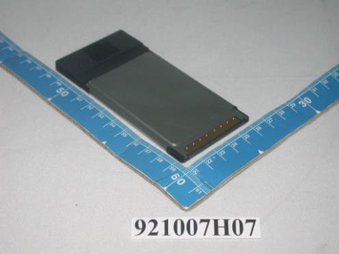
Click to zoom
Application Details
- Equipment Class
- DTS - Digital Transmission System
- Date of Grant
- Nov 11, 2003
- Application Purpose
- Original Equipment
- Date of Application
- Nov 11, 2003
- Equipment Note
- Wireless-G Notebook Adapter
- Frequency Range
- 2412.00000000 - 2462.00000000
- Company
- LINKSYS LLC
- Country
- United States
Documents & Files
Document Text
Text extracted from the exhibit documents filed with the FCC. Open a document above to read the original.
Users Manual
Wireless-G Notebook Adapter User’s Manual Rev Draft. User’s Manual 2 Federal Communication Commission Interference Statement This equipment has been tested and found to comply with the limits for a Class B digital device, pursuant to Part 15 of the FCC Rules. These limits are designed to provide reasonable protection against harmful interference in a residential installation. This equipment generates, uses and can radiate radio frequency energy and, if not installed and used in accordance with the instructions, may cause harmful interference to radio communications. However, there is no guarantee that interference will not occur in a particular installation. If this equipment does cause harmful interference to radio or television reception, which can be determined by turning the equipment off and on, the user is encouraged to try to correct the interference by one of the following measures: - Reorient or relocate the receiving antenna. - Increase the separation between the equipment and receiver. - Connect the equipment into an outlet on a circuit different from that to which the receiver is connected. - Consult the dealer or an experienced radio/TV technician for help. FCC Caution: Any changes or modifications not expressly approved by the party responsible for compliance could void the user's authority to operate this equipment. This device complies with Part 15 of the FCC Rules. Operation is subject to the following two conditions: (1) This device may not cause harmful interference, and (2) this device must accept any interference received, including interference that may cause undesired operation. IMPORTANT NOTE: FCC Radiation Exposure Statement: This equipment complies with FCC radiation exposure limits set forth for an uncontrolled environment,voefs!58!DGS!3/21:4!qbsbhsbqi!)e*)3*/! ! This transmitter must not be co-located or operating in conjunction with any other antenna or transmitter. ˟˼́˾̆̌̆ʳ˷˸˶˿˴̅˸ʳ̇˻˴̇ʳ˪ˣ˖ˈˇ ̊˩˄ˁ˅ ʳ (Wireless-G Notebook Adapter) is limited in CH1~CH11 by specified firmware controlled in USA. . User’s Manual 3 About this manual This User’ s Manual describes how to install and operate your CardBus Wireless LAN Card. Please read this manual before you install the product. This manual includes the following topics: ¾ Product description and features. ¾ Hardware installation procedure. ¾ Software installation procedure. ¾ FAQ User’s Manual 4 Table of Contents About this manual..........................................................................................3 Chapter 1 - Introduction.................................................5 Features..................................................................................................5 What is Wireless LAN?...........................................................................6 Wireless LAN Modes..............................................................................6 Notes on Wireless LAN Configuration...................................................7 Chapter 2 - Hardware Installation...................................8 Package Contents...................................................................................8 System Requirements for the Adapter...................................................8 Hardware description..............................................................................8 Inserting the Wireless LAN Card............................................................8 LED Indicators .........................................................................................9 Ejecting the Wireless LAN card..............................................................9 Chapter 3 – Driver Installation for Windows.................. 11 Driver installation for Windows 98........................................................11 Driver installation for Windows 2000................................................... 14 Driver installation for Windows ME ..................................................... 17 Driver installation for Windows XP ...................................................... 19 Chapter 4 – Installing and Using the Wireless Utility.....21 Installation in Windows........................................................................ 21 Using Wireless Utility In Windows XP................................................. 24 Use Windows Wireless Network Configuration..........................................24 Use Wireless LAN Utility................................................................................27 Use Wireless LAN Utility In Windows 98, 2000 and ME .................... 30 Configuring the CardBus Wireless LAN Card..................................... 30 Chapter 5 – Installing Network Protocols......................34 Installing the Network Protocols for Windows 98 and Millennium..... 34 Appendix A – FAQ.......................................................37 Appendix B – Specifications........................................38 User’s Manual 5 Chapter 1 - Introduction Thank you for purchasing theCardBus Wireless LAN Card. This high-speed CardBus Wireless LAN Card provides you with an innovative wireless networking solution. The Adapter is easy to set up and use. With this innovative wireless technology, you can share files and printers on the network—without inconvenient wires! The Adapter is a network Adapter with a rate of 1, 2, 5.5, and 11 Mbps operating in the ISM band usingDirect Sequence Spread Spectrum (DSSS) transmission implementing the IEEE802.11b standard. ThisAdapter provides Device Drivers for WindowsOperating Systems. It also provides tools for the configuration of the Adapter. The tool, as well as the installation steps of the plug-and-playprocedure for the Windows operating systems, is described in this document. Features The CardBus Wireless LAN Card offers compliance with the IEEE 802.11b specification. This feature allows them to communicate with other wireless devices that support the standard. Features of the Adapter …
Text truncated - open the document above for the full version.
Users Manual
User Guide Wireless-G Notebook Adapter Use this Guide to install the following: WPC54G COPYRIGHT & TRADEMARKS Specifications are subject to change without notice. Copyright © 2003 Cisco Systems, Inc. All rights reserved. Linksys is a registered trademarks of Cisco Systems, Inc. Other brands and product names are trademarks or registered trademarks of their respective holders. LIMITED WARRANTY Linksys guarantees that every Wireless-G Notebook Adapterwill be free from physical defects in material and workmanship for three years from the date of purchase, when used within the limits set forth in the Specifications section of this User Guide. This Warranty is valid and may be processed only in the country of purchase. If the product proves defective during this warranty period, go to the Linksys website at www.linksys.comfor complete RMA(Return Merchandise Authorization) assistance. You can also call Linksys Technical Support in order to obtain a RMA Number. BE SURE TO HAVE YOUR PROOF OF PURCHASE AND A BARCODE FROM THE PRODUCT’S PACK- AGING ON HAND WHEN CALLING. RETURN REQUESTS CANNOT BE PROCESSED WITHOUT PROOF OF PURCHASE. When returning a product, mark the RMA Number clearly on the outside of the package and include a copy of your original proof of pur- chase. All customers located outside of the United States of America and Canada shall be held responsible for shipping and handling charges. IN NO EVENT SHALL LINKSYS’S LIABILITY EXCEED THE PRICE PAID FOR THE PROD- UCT FROM DIRECT, INDIRECT, SPECIAL, INCIDENTAL, OR CONSEQUENTIAL DAM- AGES RESULTING FROM THE USE OF THE PRODUCT, ITS ACCOMPANYING SOFT- WARE, OR ITS DOCUMENTATION. LINKSYS DOES NOT OFFER REFUNDS FOR ANY PRODUCT. Linksys makes no warranty or representation, expressed, implied, or statuto- ry, with respect to its products or the contents or use of this documentation and all accompanying software, and specifically disclaims its quality, performance, mer- chantability, or fitness for any particular purpose. Linksys reserves the right to revise or update its products, software, or documentation without obligation to notify any individ- ual or entity. Please direct all inquiries to: Linksys P.O. Box 18558, Irvine, CA 92623. SAFETYAND REGULATORY NOTICES FCC STATEMENT This Wireless-G Notebook Adapterhas been tested and complies with the specifications for a Class B digital device, pursuant to Part 15 of the FCC Rules. These limits are designed to provide reasonable protection against harmful interference in a residential installation. This equipment generates, uses, and can radiate radio frequency energy and, if not installed and used according to the instructions, may cause harmful interfer- ence to radio communications. However, there is no guarantee that interference will not occur in a particular installation. If this equipment does cause harmful interference to radio or television reception, which is found by turning the equipment off and on, the user is encouraged to try to correct the interference by one or more of the following measures: • Reorient or relocate the receiving antenna • Increase the separation between the equipment or devices • Connect the equipment to an outlet other than the receiver’s • Consult a dealer or an experienced radio/TV technician for assistance FCC Caution: Any change or modification to the product not expressly approved by Linksys could void the user’s authority to operate the device. FCC Radiation Exposure Statement This transmitter must not be co-located or operating in conjunction with any other ant na or transmitter. This equipment has been SAR-evaluated for use in laptops (notebooks) with side slot configuration. End-users must be provided with specific operations for satisfying RF exposure compli- ance. INDUSTRY CANADA (CANADA) This Class B digital apparatus complies with Canadian ICES-003. Cet appareil numérique de la classe B est conforme à la norme NMB-003 du Canada. The use of this device in a system operating either partially or completely outdoors may require the user to obtain a license for the system according to the Canadian regulations. EC DECLARATION OF CONFORMITY (EUROPE) Linksys declares that the product included conforms to the specifications listed below, following the provisions of the EMC Directive 89/336/EEC and Low Voltage Directive 73/23/EEC: •ETS 300-826, 301 489-1 General EMC requirements for Radio equipment. •EN 609 50 Safety •ETS 300-328-2 Technical requirements for Radio equipment. Note: This equipment is intended to be used in all EU and EFTA countries. Outdoor use may be restricted to certain frequencies and/or may require a license for operation. For more details, contact Linksys Corporate Compliance. Note: Combinations of power levels and antennas resulting in a radiated power level of above 100 mW are considered as not compliant with the above mentioned directive and are not allowed for use within the European community and countries that have adopted the European R&TTE directive 1999/5/EC and/or the CEPT recommendation Rec 70.03. For more details on legal combinations of power levels and antennas, contact Linksys Corporate Compliance. •Linksys vakuuttaa täten että Wireless-G Ethernet Bridge tyyppinen laite on direktiivin 1999/5/EY, direktiivin 89/336/EEC ja direktiivin 73/23/EEC oleellisten vaatimusten ja sitä koskevien näiden direktiivien muiden ehtojen mukainen. •Linksys déclare que le pont Ethernet sans fil Gest conforme aux conditions essen- tielles et aux dispositions relatives à la directive 1999/5/EC, la directive 89/336/EEC, et à la directive 73/23/EEC. •Belgique B L’utilisation en extérieur est autorisé sur le canal 11 (2462 MHz), 12 (2467 MHz), et 13 (2472 MHz). Dans le cas d’une utilisation privée, à l’extérieur d’un bâtiment, au-dessus d’un espace public, aucun enregistrement n’est nécessaire pour une distance de moins de 300m. Pour une distance supérieure à 300m un enregistrement auprès de l’IBPT est requise. Pour une utilisation publique à l’extérieu…
Text truncated - open the document above for the full version.
External Photos
Page 1 CONSTRUCTION PHOTOS OF EUT
Internal Photos
Page 2 Page 3 Page 4 Page 5 Page 6
Operational Description
FCC ID: Q87-WPC54GV12 ADT No. 921013H03 Operational Description This device is a Wireless-G Notebook Adapter, the maximum data rate could be up to 54Mbps which OFDM technique will be applied. If the signal to noise radio is too poor which could not support 54Mbps, the 11Mbps data rate with CCK technique will be applied. The transmitter of the EUT (Wireless-G Notebook Adapter) is powered by from host equipment. The antenna type used in this product is Chip Antenna without connector. The other instruction, please have a look at the users manual.
RF Exposure Info
FCC ID: Q87-WPC54GV12 Report No.: SA921007H07A 1 Issued: Oct. 24 2003 SAR TEST REPORT REPORT NO.: SA921007H07A MODEL NO.: WPC54G V1.2 RECEIVED: Oct. 21 2003 TESTED: Oct. 22 2003 APPLICANT: Cisco-Linksys, LLC ADDRESS: 17401 Armstrong Ave. Irvine, CA 92614 ISSUED BY: Advance Data Technology Corporation LAB LOCATION: 47 14th Lin, Chiapau Tsun, Linko, Taipei, Taiwan, R.O.C. This test report consists of 31 pages in total. It may be duplicated completely for legal use with the approval of the applicant. It should not be reproduced except in full, without the written approval of our laboratory. The client should not use it to claim product endorsement by CNLA or any government agencies. The test results in the report only apply to the tested sample. 0528 ILAC MRA FCC ID: Q87-WPC54GV12 Report No.: SA921007H07A 2 Issued: Oct. 24 2003 Table of Contents 1. CERTIFICATION...............................................................................................................3 2. GENERAL INFORMATION................................................................................................4 2.1 GENERAL DESCRIPTION OF EUT...................................................................................4 2.2 GENERAL DESCRIPTION OF APPLIED STANDARDS.......................................................5 2.3 GENERAL INOFRMATION OF THE SAR SYSTEM.............................................................5 2.4 GENERAL DESCRIPTION OF THE SPATIAL PEAK SAR EVALUATION .............................9 3. DESCRIPTION OF TEST MODES AND CONFIGURATIONS............................................13 4. DESCRIPTION OF SUPPORT UNITS..............................................................................14 5. TEST RESULTS.............................................................................................................15 5.1 TEST PROCEDURES.....................................................................................................15 5.2 MEASURED SAR RESULT.............................................................................................16 5.3 SAR LIMITS...................................................................................................................18 5.4 RECIPES FOR TISSUE SIMULATING LIQUIDS...............................................................18 5.5 TEST EQUIPMENT FOR TISSUE PROPERTY.................................................................20 6. SYSTEM VALIDATION....................................................................................................21 6.1 TEST EQUIPMENT.........................................................................................................21 6.2 TEST PROCEDURE.......................................................................................................21 6.3 VALIDATION RESULT.....................................................................................................23 6.4 SYSTEM VALIDATION UNCERTAINTIES........................................................................24 7. MEASUREMENT SAR PROCEDURE UNCERTAINTIES..................................................25 7.1 PROBE CALIBRATION UNCERTAINTY...........................................................................25 7.2 ISOTROPY UNCERTAINTY............................................................................................25 7.3 BOUNDARY EFFECT UNCERTAINTY.............................................................................26 7.4 PROBE LINEARITY UNCERTAINTY................................................................................26 7.5 READOUT ELECTRONICS UNCERTAINTY.....................................................................26 7.6 RESPONSE TIME UNCERTAINTY..................................................................................27 7.7 INTEGRATION TIME UNCERTAINTY..............................................................................28 7.8 PROBE POSITIONER MECHANICAL TOLERANCE.........................................................28 7.9 PROBE POSITIONING...................................................................................................29 7.10 PHANTOM UNCERTAINTY.............................................................................................29 7.11 DASY4 UNCERTAINTY BUDGET....................................................................................30 8. INFORMATION ON THE TESTING LABORATORIES.......................................................31 APPENDIX A: TEST CONFIGURATIONS AND TEST DATA APPENDIX B: ADT SAR MEASUREMENT SYSTEM APPENDIX C: PHOTOGRAPHS OF SYSTEM VALIDATION APPENDIX D: SYSTEM CERTIFICATE & CALIBRATION FCC ID: Q87-WPC54GV12 Report No.: SA921007H07A 3 Issued: Oct. 24 2003 1. CERTIFICATION PRODUCT : Wireless-G Notebook Adapter MODEL NO. : WPC54G V1.2 BRAND NAME : Linksys APPLICANT : Cisco-Linksys, LLC TEST ITEM : Engineering sample STANDARDS : 47 CFR Part 2 (Section 2.1093), FCC OET Bulletin 65, Supplement C (01-01), RSS-102 We, Advance Data Technology Corporation, hereby certify that one sample of the designation has been tested in our facility on Oct. 22, 2003. The test record, data evaluation and Equipment Under Test (EUT) configurations represented herein are true and accurate, and it was tested according to the standards listed above. This device was found to be in compliance with the Specific Absorption Rate (SAR) requirement specified in FCC part 2.1093 under General Population / Uncontrolled Exposure condition. FCC ID: Q87-WPC54GV12 Report No.: SA921007H07A 4 Issued: Oct. 24 2003 2. GENERAL INFORMATION 2.1 GENERAL DESCRIPTION OF EUT PRODUCT Wireless-G Notebook Adapter MODEL NO. WPC54G V1.2 POWER SUPPLY 3.3VDC powered by host equipment CLASSIFICATION Portable device, production unit MODULATION TYPE BPSK, QPSK, CCK, 16QAM, 64QAM RADIO TECHNOLOGY DSSS/OFDM TRANSFER RATE UP TO 54Mbps FREQUENCY RANGE 2412MHz ~ 2462MHz NUMBER OF CHANNEL 11 CONDUCTED OUTPUT POWER 18.29dBm for 802.11b 17.31dBm for 802.11g ANTENNA TYPE…
Text truncated - open the document above for the full version.
RF Exposure Info
Page 1 APPENDIX A: TEST CONFIGURATIONS AND TEST DATA A1: TEST CONFIGURATION Mode 1 The bottom of the EUT to the phantom distance is 13mm Page 2 Mode 2 The Front of the EUT to the phantom distance is 10mm Page 3 Mode 3 The tip of the EUT to the phantom distance is 0mm Page 4 Mode 4 The tip of the EUT to the phantom distance is 0mm Page 5 EUT Photo Page 6 Liquid Level Photo 2450MHz D=152mm Date/Time: 10/22/03 10:24:10 Test Laboratory: Advance Data Technology WPC54G V1.2 Mode 1 DUT: Wireless-G Notebook Adapter ; Type: WPC54G V1.2 ; Test Channel Frequency: 2412 MHz Communication System: 802.11b ; Frequency: 2412 MHz; Duty Cycle: 1:1; Modulation type: CCK Medium: MSL2450 (σ = 1.881 mho/m, ε r = 52.937, ρ = 1000 kg/m 3 ) ; Liquid level : 152mm Phantom section: Flat Section ; Separation distance : 13mm(The bottom of the EUT to the Phantom) Antenna type : Internal Antenna ; Air temp. : 23.0 degrees ; Liquid temp. : 22.0 degrees DASY4 Configuration: - Probe: ET3DV6 - SN1687; ConvF(4.4, 4.4, 4.4); Calibrated: 2002/9/28 - Sensor-Surface: 4mm (Mechanical Surface Detection) - Electronics: DAE3 Sn541; - Phantom: SAM Twin Phantom V4.0; Type: QD 000 P40 CA; Serial: TP-1150 - Measurement SW: DASY4, V4.1 Build 47; Postprocessing SW: SEMCAD, V1.6 Build 115 Channel 1/Area Scan (41x71x1): Measurement grid: dx=20mm, dy=20mm Reference Value = 11.3 V/m Power Drift = 0.06 dB Maximum value of SAR = 0.691 mW/g Channel 1/Zoon Scan (7x7x7)/Cube 0: Measurement grid: dx=5mm, dy=5mm, dz=5mm Peak SAR (extrapolated) = 1.15 W/kg SAR(1 g) = 0.569 mW/g; SAR(10 g) = 0.306 mW/g Reference Value = 11.3 V/m Power Drift = 0.06 dB Maximum value of SAR = 0.611 mW/g Date/Time: 10/22/03 10:53:22 Test Laboratory: Advance Data Technology WPC54G V1.2 Mode 1 DUT: Wireless-G Notebook Adapter ; Type: WPC54G V1.2 ; Test Channel Frequency: 2437 MHz Communication System: 802.11b ; Frequency: 2437 MHz; Duty Cycle: 1:1; Modulation type: CCK Medium: MSL2450 (σ = 1.927 mho/m, ε r = 52.876, ρ = 1000 kg/m 3 ) ; Liquid level : 152mm Phantom section: Flat Section ; Separation distance : 13mm(The bottom of the EUT to the Phantom) Antenna type : Internal Antenna ; Air temp. : 23.0 degrees ; Liquid temp. : 22.0 degrees DASY4 Configuration: - Probe: ET3DV6 - SN1687; ConvF(4.4, 4.4, 4.4); Calibrated: 2002/9/28 - Sensor-Surface: 4mm (Mechanical Surface Detection) - Electronics: DAE3 Sn541; - Phantom: SAM Twin Phantom V4.0; Type: QD 000 P40 CA; Serial: TP-1150 - Measurement SW: DASY4, V4.1 Build 47; Postprocessing SW: SEMCAD, V1.6 Build 115 Channel 6/Area Scan (41x71x1): Measurement grid: dx=20mm, dy=20mm Reference Value = 11.3 V/m Power Drift = -0.3 dB Maximum value of SAR = 0.615 mW/g Channel 6/Zoon Scan (7x7x7)/Cube 0: Measurement grid: dx=5mm, dy=5mm, dz=5mm Peak SAR (extrapolated) = 1.13 W/kg SAR(1 g) = 0.535 mW/g; SAR(10 g) = 0.279 mW/g Reference Value = 11.3 V/m Power Drift = -0.3 dB Maximum value of SAR = 0.572 mW/g Date/Time: 10/22/03 11:11:26 Test Laboratory: Advance Data Technology WPC54G V1-2 Mode 1 DUT: Wireless-G Notebook Adapter ; Type: WPC54G V1.2 ; Test Channel Frequency: 2462 MHz Communication System: 802.11b ; Frequency: 2462 MHz; Duty Cycle: 1:1; Modulation type: CCK Medium: MSL2450 (σ = 1.971 mho/m, ε r = 52.783, ρ = 1000 kg/m 3 ) ; Liquid level : 152mm Phantom section: Flat Section ; Separation distance : 13mm(The bottom of the EUT to the Phantom) Antenna type : Internal Antenna ; Air temp. : 23.0 degrees ; Liquid temp. : 22.0 degrees DASY4 Configuration: - Probe: ET3DV6 - SN1687; ConvF(4.4, 4.4, 4.4); Calibrated: 2002/9/28 - Sensor-Surface: 4mm (Mechanical Surface Detection) - Electronics: DAE3 Sn541; - Phantom: SAM Twin Phantom V4.0; Type: QD 000 P40 CA; Serial: TP-1150 - Measurement SW: DASY4, V4.1 Build 47; Postprocessing SW: SEMCAD, V1.6 Build 115 Channel 11/Area Scan (41x71x1): Measurement grid: dx=20mm, dy=20mm Reference Value = 9.85 V/m Power Drift = 0.3 dB Maximum value of SAR = 0.505 mW/g Channel 11/Zoon Scan (7x7x7)/Cube 0: Measurement grid: dx=5mm, dy=5mm, dz=5mm Peak SAR (extrapolated) = 1.05 W/kg SAR(1 g) = 0.453 mW/g; SAR(10 g) = 0.222 mW/g Reference Value = 9.85 V/m Power Drift = 0.3 dB Maximum value of SAR = 0.51 mW/g Date/Time: 10/22/03 12:07:40 Test Laboratory: Advance Data Technology WPC54G V1-2 Mode 2 DUT: Wireless-G Notebook Adapter ; Type: WPC54G V1.2 ; Test Channel Frequency: 2412 MHz Communication System: 802.11b ; Frequency: 2412 MHz; Duty Cycle: 1:1; Modulation type: CCK Medium: MSL2450 (σ = 1.881 mho/m, ε r = 52.937, ρ = 1000 kg/m 3 ) ; Liquid level : 152mm Phantom section: Flat Section ; Separation distance : 10 mm(The front of the EUT to the Phantom) Antenna type : Internal Antenna ; Air temp. : 23 degrees ; Liquid temp. : 22 degrees DASY4 Configuration: - Probe: ET3DV6 - SN1687; ConvF(4.4, 4.4, 4.4); Calibrated: 2002/9/28 - Sensor-Surface: 4mm (Mechanical Surface Detection) - Electronics: DAE3 Sn541; Calibrated: 2003/1/14 - Phantom: SAM Twin Phantom V4.0; Type: QD 000 P40 CA; Serial: TP-1150 - Measurement SW: DASY4, V4.1 Build 47; Postprocessing SW: SEMCAD, V1.6 Build 115 Channel 1/Area Scan (41x71x1): Measurement grid: dx=20mm, dy=20mm Reference Value = 11.8 V/m Power Drift = -0.3 dB Maximum value of SAR = 0.633 mW/g Channel 1/Zoon Scan (7x7x7)/Cube 0: Measurement grid: dx=5mm, dy=5mm, dz=5mm Peak SAR (extrapolated) = 1.01 W/kg SAR(1 g) = 0.521 mW/g; SAR(10 g) = 0.283 mW/g Reference Value = 11.8 V/m Power Drift = -0.3 dB Maximum value of SAR = 0.548 mW/g Date/Time: 10/22/03 12:26:00 Test Laboratory: Advance Data Technology WPC54G V1.2 Mode 2 DUT: Wireless-G Notebook Adapter ; Type: WPC54G V1.2 ; Test Channel Frequency: 2437 MHz Communication System: 802.11b ; Frequency: 2437 MHz; Duty Cycle: 1:1; Modulation type: CCK Medium: MSL2450 (σ = 1.927 mho/m, ε r = 52.876, ρ = 1000 kg/m 3 ) ; Liquid level : 152mm Phantom section: Flat Section ; Separation distance : 10 mm(The front of the EUT to the Phantom) Antenna type : Internal Antenna ; Air temp. : 23 degrees ; Liquid temp. : 22 degrees DASY4 Configuration: …
Text truncated - open the document above for the full version.
RF Exposure Info
APPENDIX B: ADT SAR MEASUREMENT SYSTEM APPENDIX C: PHOTOGRAPHS OF SYSTEM VALIDATION
RF Exposure Info
APPENDIX D: SYSTEM CERTIFICATE & CALIBRATION D1: SAM PHANTOM D2: 2450MHZ SYSTEM VALIDATION DIPOLE D3: DOSIMETRIC E-FIELD PROBE
Test Report
FCC ID: Q87-WPC54GV12 Report No.: RF921007H07A 1 Issued: Nov. 06, 2003 ADT No.: 921013H03 FCC TEST REPORT REPORT NO.: RF921007H07A MODEL NO.: WPC54G V1.2 RECEIVED: Oct. 08, 2003 TESTED: Oct. 17 to 22, 2003 APPLICANT: Cisco-Linksys, LLC ADDRESS: 17401 Armstrong Ave. Irvine, CA 92614 ISSUED BY: Advance Data Technology Corporation LAB LOCATION: No. 81-1, Lu Liao Keng, 9 Ling, Wu Lung Tsuen, Chiung Lin Hsiang, Hsin Chu Hsien, Taiwan, R.O.C. This test report consists of 58 pages in total. It may be duplicated completely for legal use with the approval of the applicant. It should not be reproduced except in full, without the written approval of our laboratory. The client should not use it to claim product endorsement by CNLA, NVLAP or any government agencies. The test results in the report only apply to the tested sample. 0536 ILAC MRA Lab Code: 200376-0 FCC ID: Q87-WPC54GV12 Report No.: RF921007H07A 2 Issued: Nov. 06, 2003 ADT No.: 921013H03 Table of Contents 1 CERTIFICATION.......................................................................................................4 2 SUMMARY OF TEST RESULTS...........................................................................5 3 GENERAL INFORMATION.....................................................................................6 3.1 GENERAL DESCRIPTION OF EUT......................................................................6 3.2 DESCRIPTION OF TEST MODES........................................................................7 3.3 GENERAL DESCRIPTION OF APPLIED STANDARDS...................................7 3.4 DESCRIPTION OF SUPPORT UNITS.................................................................8 4 TEST TYPES AND RESULTS................................................................................9 4.1 CONDUCTED EMISSION MEASUREMENT......................................................9 4.1.1 LIMITS OF CONDUCTED EMISSION MEASUREMENT..................................9 4.1.2 TEST INSTRUMENTS.............................................................................................9 4.1.3 TEST SETUP..........................................................................................................10 4.1.4 EUT OPERATING CONDITIONS........................................................................11 4.1.5 TEST RESULTS.....................................................................................................12 4.2 RADIATED EMISSION MEASUREMENT..........................................................14 4.2.1 LIMITS OF RADIATED EMISSION MEASUREMENT.....................................14 4.2.2 TEST INSTRUMENTS...........................................................................................15 4.2.3 TEST PROCEDURES...........................................................................................16 4.2.4 TEST SETUP..........................................................................................................17 4.2.5 EUT OPERATING CONDITIONS........................................................................17 4.2.6 TEST RESULTS.....................................................................................................18 4.2.7 TEST RESULTS - DSSS.......................................................................................19 4.2.8 TEST RESULTS -OFDM.......................................................................................22 4.3 6dB BANDWIDTH MEASUREMENT..................................................................25 4.3.1 LIMITS OF 6dB BANDWIDTH MEASUREMENT.............................................25 4.3.2 TEST INSTRUMENTS...........................................................................................25 4.3.3 TEST PROCEDURE..............................................................................................26 4.3.4 TEST SETUP..........................................................................................................26 4.3.5 EUT OPERATING CONDITIONS........................................................................26 4.3.6 TEST RESULTS-DSSS.........................................................................................27 4.3.7 TEST RESULTS-OFDM........................................................................................31 4.4 MAXIMUM PEAK OUTPUT POWER..................................................................35 4.4.1 LIMITS OF MAXIMUM PEAK OUTPUT POWER MEASUREMENT.............35 4.4.2 TEST INSTRUMENTS...........................................................................................35 4.4.3 TEST PROCEDURES...........................................................................................36 FCC ID: Q87-WPC54GV12 Report No.: RF921007H07A 3 Issued: Nov. 06, 2003 ADT No.: 921013H03 4.4.4 TEST SETUP..........................................................................................................36 4.4.5 EUT OPERATING CONDITIONS........................................................................36 4.4.6 TEST RESULTS- DSSS........................................................................................37 4.4.7 TEST RESULTS- OFDM.................…
Text truncated - open the document above for the full version.
Contact Information
Applicant
Po-Wen Cheng(Regulatory Compliance Manager)
Technical Contact
Advance Data Technology CorporationEric Lin
[email protected]+886 3593 5343
81-1 Luliaoken, 9th Lin, Wulung Tsuen Chiunglin · Hsinchu · Taiwan
Test Firm
Bureau Veritas CPS (H.K.) Ltd. Taoyuan BranchRichard Chen
Technical Specifications
| # | Rule Parts | Frequency Range | Power Output |
|---|---|---|---|
| 1 | 15C | 2.41 GHz - 2.46 GHz | 66.70 mW |
Other Applications from LINKSYS LLC

Q87-WDS060
Aug 11, 2020WiFi Smart Light Switch with Dimmer
Equipment Class
DTS - Digital Transmission System
Q87-03564
Jun 28, 2020Linksys Tri-Band Wireless-AC Router
Equipment Class
NII - Unlicensed National Information Infrastructure TX
Q87-03566
Jun 23, 2020Linksys Tri-Band Wireless-AC Router
Equipment Class
NII - Unlicensed National Information Infrastructure TX
Q87-03530
Apr 29, 2020Linksys MAX-STREAM AC1900+ WiFi Range Extender
Equipment Class
NII - Unlicensed National Information Infrastructure TX
Q87-08151
Mar 30, 2020Linksys Dual-Band 802.11ax Wireless Router
Equipment Class
DTS - Digital Transmission System