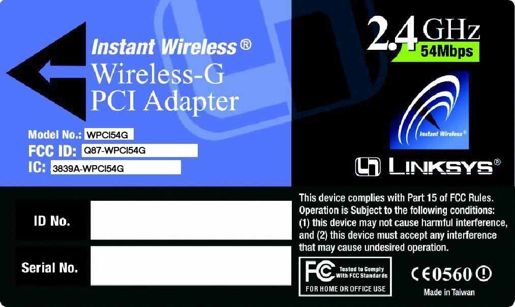
Q87-WPCI54GWireless-G PCI Adapter
LINKSYS LLC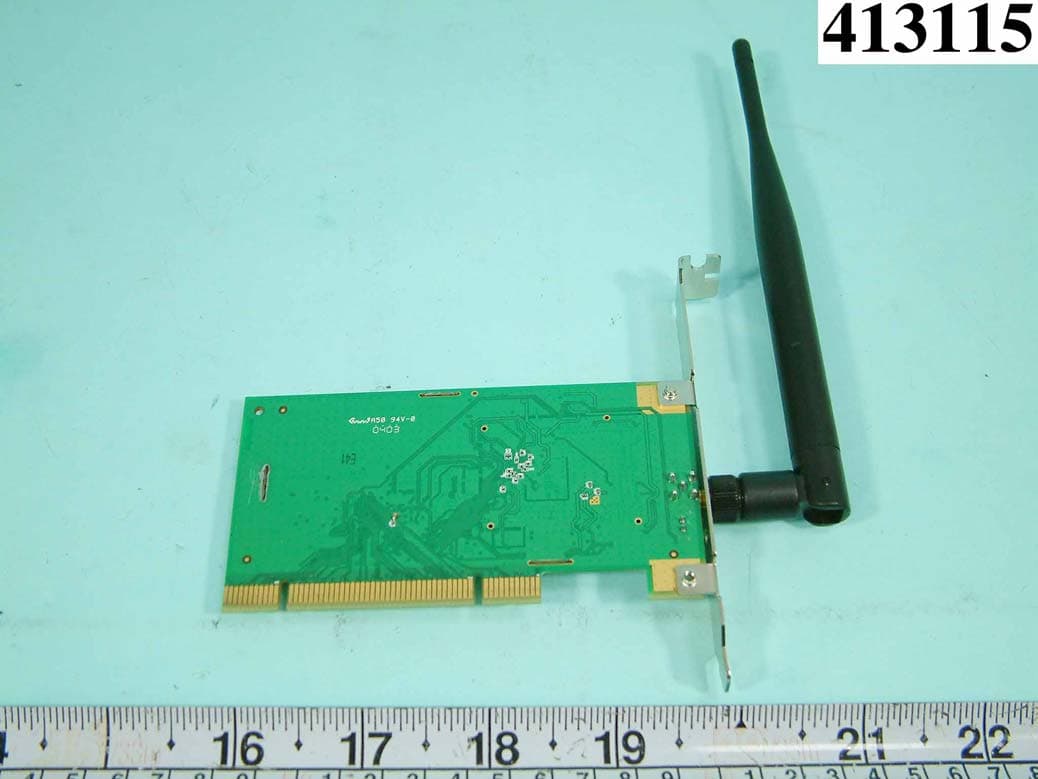
Click to zoom
Application Details
- Equipment Class
- DTS - Digital Transmission System
- Date of Grant
- Apr 18, 2004
- Application Purpose
- Original Equipment
- Date of Application
- Apr 18, 2004
- Equipment Note
- Wireless-G PCI Adapter
- Frequency Range
- 2412.00000000 - 2462.00000000
- Company
- LINKSYS LLC
- Country
- United States
Documents & Files
Document Text
Text extracted from the exhibit documents filed with the FCC. Open a document above to read the original.
Users Manual
Instant Wireless ® Series User Guide Wireless-G PCI Adapter Use this Guide to install: WMP54G COPYRIGHT & TRADEMARKS Specifications are subject to change without notice. Copyright © 2003 Linksys, All Rights Reserved. Instant Wireless, Linksys, and the Linksys logo are registered trademarks of Linksys Group, Inc. Microsoft, Windows, and the Windows logo are registered trade- marks of Microsoft Corporation. All other trademarks and brand names are the proper- ty of their respective proprietors. LIMITED WARRANTY Linksys guarantees that every Instant Wireless ® Wireless-G PCI Adapter will be free from physical defects in material and workmanship for three years from the date of purchase, when used within the limits set forth in the Specifications section of this User Guide. ThisWarrantyisvalidandmaybeprocessedonlyinthecountryofpurchase. If the product proves defective during this warranty period, go to the Linksys website at www.linksys.comfor complete RMA (Return Merchandise Authorization) assistance. You can also call Linksys Technical Support in order to obtain a RMA Number. BE SURE TO HAVE YOUR PROOF OF PURCHASE AND A BARCODE FROM THE PRODUCT’S PACK- AGING ON HAND WHEN CALLING. RETURN REQUESTS CANNOT BE PROCESSED WITHOUT PROOF OF PURCHASE. When returning a product, mark the RMA Number clearly on the outside of the package and include a copy of your original proof of pur- chase. All customers located outside of the United States of America and Canada shall be held responsible for shipping and handling charges. IN NO EVENT SHALL LINKSYS'S LIABILITY EXCEED THE PRICE PAID FOR THE PROD- UCT FROM DIRECT, INDIRECT, SPECIAL, INCIDENTAL, OR CONSEQUENTIAL DAM- AGES RESULTING FROM THE USE OF THE PRODUCT, ITS ACCOMPANYING SOFT- WARE, OR ITS DOCUMENTATION. LINKSYS OFFERS NO REFUNDS FOR ITS PROD- UCTS. Linksys makes no warranty or representation, expressed, implied, or statutory, with respect to its products or the contents or use of this documentation and all accom- panying software, and specifically disclaims its quality, performance, merchantability, or fitness for any particular purpose. Linksys reserves the right to revise or update its prod- ucts, software, or documentation without obligation to notify any individual or entity. Please direct all inquiries to: Linksys P.O. Box 18558, Irvine, CA 92623. SAFETY AND REGULATORY NOTICES FCC STATEMENT The Instant Wireless ® Wireless-G PCI Adapter has been tested and complies with the specifications for a Class B digital device, pursuant to Part 15 of the FCC Rules. Operation is subject to the following two conditions: (1) This device may not cause harmful interference, and (2) This device must accept any interference received, including interference that may cause undesired operation. These limits are designed to provide reasonable protection against harmful interference in a residential installation. This equipment generates, uses, and can radiate radio fre- quency energy and, if not installed and used according to the instructions, may cause harmful interference to radio communications. However, there is no guarantee that inter- ference will not occur in a particular installation. If this equipment does cause harmful interference to radio or television reception, which is found by turning the equipment off and on, the user is encouraged to try to correct the interference by one or more of the following measures: •Reorient or relocate the receiving antenna •Increase the separation between the equipment or devices •Connect the equipment to an outlet other than the receiver's •Consult a dealer or an experienced radio/TV technician for assistance FCC Caution: Any change or modification to the product not expressly approved by Linksys could void the user's authority to operate the device. FCC RF Radiation Exposure Statement To comply with the FCC and ANSI C95.1 RF exposure limits, the antenna(s) for this device must comply with the following: •Access points with 2.4 GHz or 5 GHz integrated antenna must operate with a sepa- ration distance of at least 20 cm from all persons using the cable provided and must not be co-located or operating in conjunction with any other antenna or transmitter. End-users must be provided with specific operations for satisfying RF exposure compli- ance. Note: Dual antennas used for diversity operation are not considered co-located. Canadian Department of Communications Industry Canada (IC) Notice This Class B digital apparatus complies with Canadian ICES-003 and RSS-210. Cet appareil numérique de la classe B est conforme à la norme NMB-003 et CNR-210 du Canada. "To prevent radio interference to the licensed service, this device is intended to be oper- ated indoors and away from windows to provide maximum shielding. Equipment (or its transmit antenna) that is installed outdoors is subject to licensing." " Pour empêcher que cet appareil cause du brouillage au service faisant l'objet d'une licence, il doit être utilisé à l'intérieur et devrait être placé loin des fenêtres afin de fournir un écran de blindage maximal. Si le matériel (ou son antenne d'émission) est installé à l'extérieur, il doit faire l'objet d'une licence. " EC DECLARATION OF CONFORMITY (EUROPE) Linksys Group declares that the Instant Wireless ® Series products included in the Instant Wireless ® Series conform to the specifications listed below, following the provisions of the European R&TTE directive 1999/5/EC, EMC directive 89/336/EEC, and Low Voltage directive 73/23/EEC: For 2.4 GHz devices with 100 mW radios, the following standards were applied: •ETS 300-826, 301 489-1 General EMC requirements for Radio equipment. •EN 609 50 Safety •ETS 300-328-2 Technical requirements for Radio equipment. Caution: This equipment is intended to be used in all EU and EFTA countries. Outdoor use may be restricted to certain frequencies and/or may require a license for operation. Contact local Authority for procedure to follow. Note: Combinations of power levels and antennas resu…
Text truncated - open the document above for the full version.
Users Manual
Wireless-G Notebook Adapter 19 Instant Wireless ® Series 18 TheProfiles screen (Figure 7-6) lets you save different configuration profiles for different network setups. You can also import or export profiles. The default profile holds the initial configuration saved when you ran the Setup Wizard. Profile- Name of the connection profile. SSID- The wireless network’s unique name, as set in the connection profile. Profile Information Network Type- The mode of the wireless network currently in use. Transfer Rate- The data transfer rate of the current connection. (In Auto mode, the Adapter dynamically shifts to the fastest data transfer rate possible at any given time.) Channel- The channel to which the wireless network devices are set. WEP- The status of the WEP encryption security feature. Connect- To connect to a wireless network using a specific profile, select the profile,and click the Connectbutton. Edit- Select a profile, and click the Editbutton to change an existing profile. New- Click the Newbutton to create a new profile. See the next section, “Creating a New Profile,” for detailed instructions. Figure 7-6 Profiles Site Information Wireless Mode- The mode of the wireless network currently in use. Channel- The channel to which the wireless network devices are set. WEP- The status of the WEP encryption security feature. MAC- The MAC address of the wireless network’s access point. Surveyed at - The time at which the wireless network was scanned. Refresh- Click the Refreshbutton to perform a new search for wireless devices. Connect- To connect to one of the networks on the list, select the wireless net- work,and click the Connectbutton. If the wireless network has WEP encryp- tion enabled, you will see the screen shown in Figure 7-5. In the WEPdrop-down box, select the type of WEP encryption used by the wireless network: 64-bit, or 128-bitWEP. If the wireless network uses a passphrase, enter the passphrase in the Passphrasefield. If the wireless network uses a WEP key, enter the WEP key in the Key 1field. Click the OKbutton to complete the network connection and return to the Site Surveyscreen, or click the Cancelbutton to cancel the network connection and return to the Site Surveyscreen. On the Site Surveyscreen, click the X(Close) button in the upper right corner to exit the WLAN Monitor. Figure 7-5 Wireless-G Notebook Adapter 1. On the Profilesscreen, shown in Figure 7-6, click the Newbutton to create a new profile. 2. When the Create connection profilescreen appears (Figure 7-9), enter a name for the new profile. Click OKto save the profile name or click Cancel to return to the previous screen. 3. The Choose a network typescreen (Figure 7-10) shows a choice of two wireless modes. Click the Infrastructure Moderadio button if you want your wireless computers to communicate with computers on your wired network via a wireless access point. Click the Ad-Hoc Moderadio button if you want multiple wireless computers to communicate directly with each other. Click the Nextbutton to continue or the Backbutton to return to the previous screen. Infrastructure Mode - This mode allows wireless and wired networks to communicate through an access point. Ad-Hoc Mode - This mode allows wireless-equipped computers to com- municate directly with each other. No access point is used. 21 Instant Wireless ® Series 20 Figure 7-10 Figure 7-9 Creating a New Profile Import- Click theImportbut- ton to import a profile that has been saved in another location. From the screen that appears (shown in Figure 7-7), select the appropriate file, and click the Openbutton. Export - To save the profile(s) in a different location, click the Exportbutton. On the screen that appears (Figure 7-8), direct Windows to the appropriate fold- er and click the OKbutton. Delete- Click the Deletebutton to delete a profile. Click the X(Close) button in the upper right corner to exit the WLAN Monitor. Figure 7-7 Figure 7-8 Note:If you have more than one profile, all profiles will be auto- matically selected and exported to the same folder. Wireless-G Notebook Adapter 23 Instant Wireless ® Series 4. The Wireless Settingsscreen (Figure 7-11) will appear. If you chose Infrastructure Mode, go to Step 5now. If you chose Ad-Hoc Mode, select the correct operating channel for your network from the Channeldrop- down menu. Then, select the Network Mode from the drop-down menu. Click the Nextbutton, and go to Step 5. Click the Backbutton to change any settings. Channel- The channel you choose should match the channel set on the other devices in your wireless network. If you are unsure about which chan- nel to use, select the default channel (Channel 6). Network Mode- Select Mixed Mode, and both Wireless-G and Wireless- B computers will be allowed on the network, but the speed will be reduced. SelectG-Only Modefor maximum speed, but no Wireless-B users will be allowed on the network. 5. The Network Settingscreen (Figure 7-12) will appear. If your network has a DHCP server, click the radio button next to Obtain an IP address automatically (DHCP). Click the Nextbutton to continue, or click the Backbutton to return to the previous screen. 22 If your network does not have a DHCP server, click the radio button next to Specify the IP address. Enter an IP Address,Subnet Mask,Default Gateway, and DNSappropriate for your network. Enter each address in this format: xxx.xxx.xxx.xxx(the x’s represent the numbers that make up each address). You must specify the IP Address and Subnet Mask on this screen. If you are unsure about the Default Gateway and DNS addresses, then leave these fields alone. IP Address - This IP Address must be unique to your network. Subnet Mask - The Adapter’s Subnet Mask must be the same as your wired network’s Subnet Mask. Default Gateway - Enter the IP address of your network’s Gateway here. DNS- Enter the DNS addresses of your Ethernet (wired) network here. Click the Nextbutton to continue or the Backbutton to return to the previ- ous…
Text truncated - open the document above for the full version.
Users Manual
Wireless-G Notebook Adapter 33 Instant Wireless ® Series 32 Hop- The link between two network nodes. IEEE(TheInstitute of Electrical and ElectronicsEngineers) - The IEEE describes itself as "the world's largest technical professional society, promoting the development and application of electrotechnology and allied sciences for the benefit of humanity, the advancement of the profession, and the well-being of our members." The IEEE fosters the development of standards that often become national and international standards. The organization publishes a number of journals, has many local chapters, and several large societies in special areas, such as the IEEE Computer Society. Infrastructure Network - An infrastructure network is a group of computers or other devices, each with a wireless adapter, connected as an 802.11 wireless LAN. In infrastructure mode, the wireless devices communicate with each other and to a wired network by first going through an access point. An infra- structure wireless network connected to a wired network is referred to as a Basic Service Set (BSS). A set of two or more BSS in a single network is referred to as an Extended Service Set (ESS). Infrastructure mode is useful at a corporation scale, or when it is necessary to connect the wired and wireless networks. IP(Internet Protocol) - The method or protocol by which data is sent from one computer to another on the Internet. It is a standard set of rules, procedures, or conventions relating to the format and timing of data transmission between two computers that they must accept and use to be able to understand each other. IP Address- In the most widely installed level of the Internet Protocol (IP) today, an IP address is a 32-binary digit number that identifies each sender or receiver of information that is sent in packet across the Internet. When you request an HTML page or send e-mail, the Internet Protocol part of TCP/IP includes your IP address in the message (actually, in each of the packets if more than one is required) and sends it to the IP address that is obtained by looking up the domain name in the Uniform Resource Locator you requested or in the e-mail address you're sending a note to. At the other end, the recipient can see the IP address of the Web page requestor or the e-mail sender and can respond by sending another message using the IP address it received. IRQ(Interrupt ReQuest) - A hardware interrupt on a PC. There are 16 IRQ lines used to signal the CPU that a peripheral event has started or terminated. Except for PCI devices, two devices cannot use the same line. Driver- A workstation or server software module that provides an interface between a network interface card and the upper-layer protocol software running in the computer; it is designed for a specific card, and is installed during the initial installation of a network-compatible client or server operating system. DSSS(Direct-SequenceSpreadSpectrum) - DSSS generates a redundant bit pattern for all data transmitted. This bit pattern is called a chip (or chipping code). Even if one or more bits in the chip are damaged during transmission, statistical techniques embedded in the receiver can recover the original data without the need for retransmission. To an unintended receiver, DSSS appears as low power wideband noise and is rejected (ignored) by most narrowband receivers. However, to an intended receiver (i.e. another wireless LAN end- point), the DSSS signal is recognized as the only valid signal, and interference is inherently rejected (ignored). Encryption- A security method that applies a specific algorithm to data in order to alter the data's appearance and prevent other devices from reading the information. Ethernet- IEEE standard network protocol that specifies how data is placed on and retrieved from a common transmission medium. Has a transfer rate of 10 Mbps. Forms the underlying transport vehicle used by several upper-level protocols, including TCP/IP and XNS. FHSS(Frequency HoppingSpreadSpectrum) - FHSS continuously changes (hops) the carrier frequency of a conventional carrier several times per second according to a pseudo-random set of channels. Because a fixed frequency is not used, and only the transmitter and receiver know the hop patterns, interception of FHSS is extremely difficult. Fragmentation- Breaking a packet into smaller units when transmitting over a network medium that cannot support the original size of the packet. Gateway- A device that interconnects networks with different, incompatible communications protocols. Hardware- Hardware is the physical aspect of computers, telecommunica- tions, and other information technology devices. The term arose as a way to dis- tinguish the "box" and the electronic circuitry and components of a computer from the program you put in it to make it do things. The program came to be known as the software. Wireless-G Notebook Adapter Passphrase- Used much like a password, a passphrase simplifies the WEP encryption process by automatically generating the WEP encryption keys for Linksys products. PCI(PeripheralComponentInterconnect) - A peripheral bus commonly used in PCs, Macintoshes and workstations. It was designed primarily by Intel and first appeared on PCs in late 1993. PCI provides a high-speed data path between the CPU and peripheral devices (video, disk, network, etc.). There are typically three or four PCI slots on the motherboard. In a Pentium PC, there is generally a mix of PCI and ISA slots or PCI and EISA slots. Early on, the PCI bus was known as a "local bus." PCI provides "plug and play" capability, automatically configuring the PCI cards at startup. When PCI is used with the ISA bus, the only thing that is gen- erally required is to indicate in the CMOS memory which IRQs are already in use by ISA cards. PCI takes care of the rest. PCI allows IRQs to be shared, which helps to solve the problem of limited IRQs available on a PC. For example, if there were only one IR…
Text truncated - open the document above for the full version.
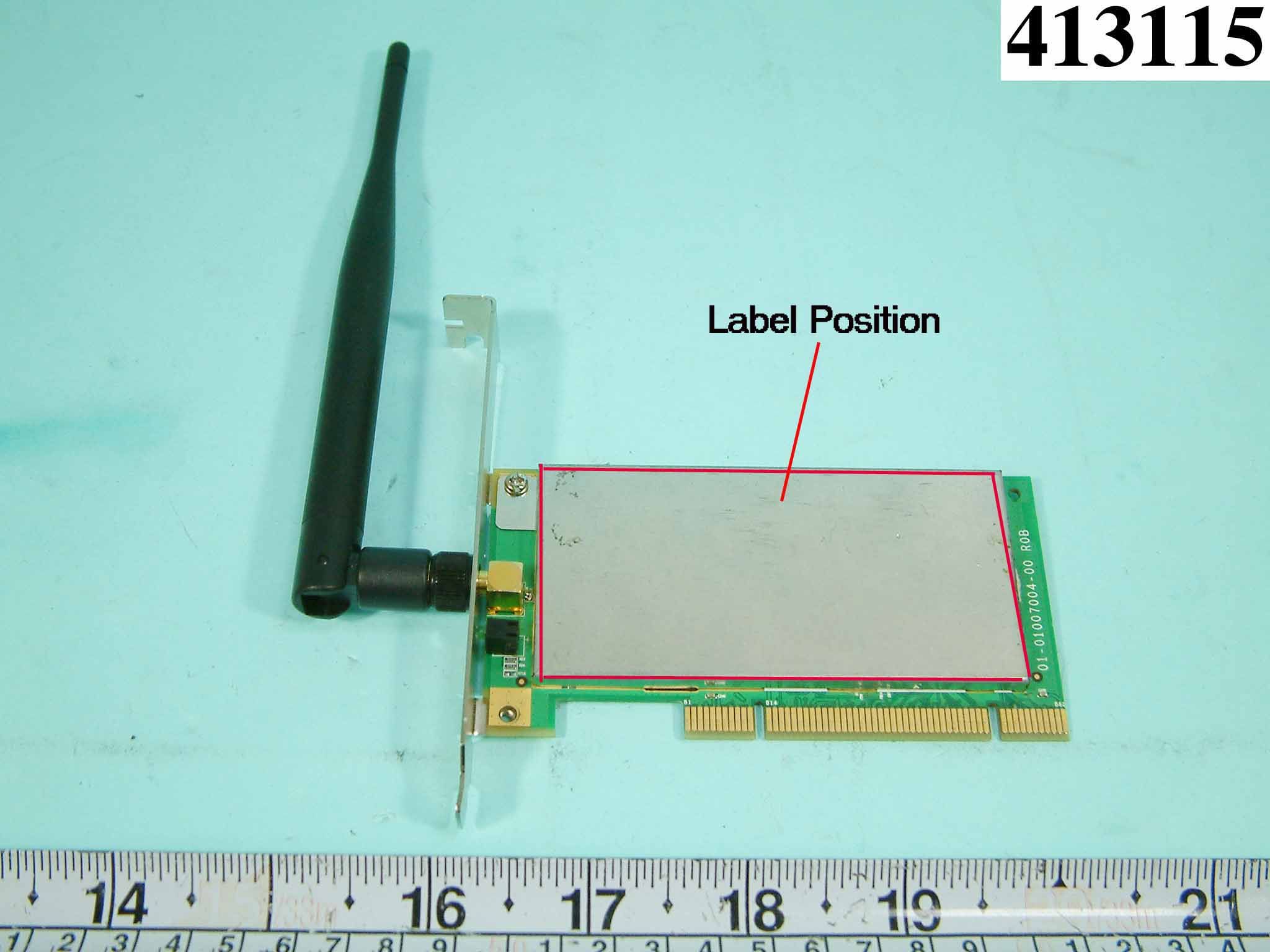
External Photos
FCC TEST REPORT REPORT NO. : F413115 SPORTON International Inc. PAGE NUMBER : A1 OF A4 TEL : 886-2-2696-2468 ISSUED DATE : Mar.19, 2004 FAX : 886-2-2696-2255 APPENDIX A. Photographs of EUT External FCC TEST REPORT REPORT NO. : F413115 SPORTON International Inc. PAGE NUMBER : A2 OF A4 TEL : 886-2-2696-2468 ISSUED DATE : Mar.19, 2004 FAX : 886-2-2696-2255 FCC TEST REPORT REPORT NO. : F413115 SPORTON International Inc. PAGE NUMBER : A3 OF A4 TEL : 886-2-2696-2468 ISSUED DATE : Mar.19, 2004 FAX : 886-2-2696-2255 FCC TEST REPORT REPORT NO. : F413115 SPORTON International Inc. PAGE NUMBER : A4 OF A4 TEL : 886-2-2696-2468 ISSUED DATE : Mar.19, 2004 FAX : 886-2-2696-2255
Internal Photos
FCC TEST REPORT REPORT NO. : F413115 SPORTON International Inc. PAGE NUMBER : B1 OF B3 TEL : 886-2-2696-2468 ISSUED DATE : Mar.19, 2004 FAX : 886-2-2696-2255 APPENDIX B. Photographs of EUT Internal FCC TEST REPORT REPORT NO. : F413115 SPORTON International Inc. PAGE NUMBER : B2 OF B3 TEL : 886-2-2696-2468 ISSUED DATE : Mar.19, 2004 FAX : 886-2-2696-2255 FCC TEST REPORT REPORT NO. : F413115 SPORTON International Inc. PAGE NUMBER : B3 OF B3 TEL : 886-2-2696-2468 ISSUED DATE : Mar.19, 2004 FAX : 886-2-2696-2255
Schematics
Title SizeDocument NumberRev Date:Sheet of 01-01007004-00R01 Tiltle_and_Rev C 112Friday, March 05, 2004 FOXCONN 802.11B/G PCI CARD Schematic draft DHL type change to DSN type 11/13/03 DESCRIPTIONREVISION NUMBER 11/17/03 Intel Reference Release DATE INTERNAL RELEASE R03 RL-01-R0A FOXCONN Wireless Home Netork 11/25/03RL-01-R0ADelete J4,J7,J8,R36,R37,R38,R39,R46 of Intel ARDON/RAMON Test connector 11/27/03RL-01-R0AChange U11 to ingnle port switch 11/28/03 RL-01-R0AAdd low pass filter on transmit loop. 11/19/03RL-01-R0AChange PCB 8 layer to 4 layer and one side placement of component 11/26/03RL-01-R0ADelete XTALOFF circuit 3/05/04R01 5 5 4 4 3 3 2 2 1 1 DD CC BB AA 1_2V_ARD 1_2V_ARD_SW 2_9V_LNA 2_9V_LNA 2_9V_LNA 3_3V 3_3V3_3V 3_3V 3_3V 3_3V 3_3V 3_3V 3_3V 3_3V_ARD 3_3V_RF 3_3V_PA 3_3V_RF 2_7V_ARD 2_7V_RMN 1_8V_RMN 3_3V 3_3V 3_3V_RF1 GPI01_M08 GDI04_M05 VCC_EXT_VCO Title SizeDocument NumberRev Date:Sheet of 01-01007004-00R01 REGULATORS A3 212Friday, March 05, 2004 CH CH CH *1.2V TO S.D ARDON FHY CH CH IC ADJ CH FOR PULSE SKIPPING MODE; R7 INSTALL, R61 REMOVE FOR BURST MODE; R61 INSTALL, R7 REMOVE POWERPOWER POWER POWER POWER POWERPOWER POWER VCO SWITCH ADDED POWER CH FOXCONN Wireless Home Netork R7 EMPTY 0 R6 EMPTY 0 C10 .1UF X5R R261 EMPTY 0 R714 750 EMPTY FB3 0 C15 10UF X5R FB32 FB C163 .047UF X5R C6 .1UF R88 100 R13 2K U301 APL53 EMPTY Vin 1 BS 2 F B 3 Vout 4 GND 5 GND 8 GND 6 GND 7 C64 10UF X5R FB4 0 FB27 FB C38 10UF X5R C39 10UF X5R C25 .1UF X5R L2 4.70UH C95 1000PF X7R C7 .01UF Q6 SI7904DN S1 1 G1 2 S2 3 G2 4 D2 5 D1 8 Q1A MOSFET IC 1 2 78 FB6 FB C16 .1UF X5R C24 .1UF U142.70V ON/OFF 3 BYP/ADJ 4 GND 2 VIN 1 VOUT 5 U9 EMPTY TI_TPS62200DBV EN 3 VI 1 GND 2 SW 5 FB 4 C154 10UF X5R C4 EMPTY C33 .1UF X5R R9 1K C2 EMPTY C42 .1UF C9 2.2UF C57 .01UF X7R C5 EMPTY R709 47K R11 1.69M C19 .01UF X7R R61 0 C18 10UF X5R C1 EMPTY C31 EMPTY U12.85V ON/OFF 3 BYP/ADJ 4 GND 2 VIN 1 VOUT 5 C17 10UF X5R R64 3.3K C36 22PF U5 ON/OFF 3 BYP/ADJ 4 GND 2 VIN 1 VOUT 5 FB1 FB FB5 0 C79 .1UF C20 10UF X5R C23 .1UF R86 EMPTY 10K R66 EMPTY 10K C14 .01UF X7R C12 .01UF X7R R715 1.5K EMPTY FB2 0 U2 ON/OFF 3 BYP/ADJ 4 GND 2 VIN 1 VOUT 5 C13 .01UF X7R R12 887K U32.85V ON/OFF 3 BYP/ADJ 4 GND 2 VIN 1 VOUT 5 R5 0 C34 .01UF X7R C93 10UF X5R C11 .1UF X5R C37 1UF X5R FB31 FB C41 .1UF C3 .1UF X5R U4 LTC3405A MODE 6 VIN 4 RUN 1 SW 3 VOUT 5 GND 2 C27 EMPTY FB7 0 5 5 4 4 3 3 2 2 1 1 DD CC BB AA 3_3V VAUX CLK VIO LOCK_N AD31 AD29 AD27 AD25 CBE3_N AD23 AD21 AD19 AD17 CBE2_N IRDY_N DEVSEL_N PERR_N SERR_N CBE1_N AD14 AD12 AD10 AD08 AD07 AD05 AD03 AD01 REQ_N INTA_N PME_N RST_N GNT_N AD30 AD28 AD26 AD24 IDSEL AD22 AD20 AD18 AD16 FRAME_N TRDY_N STOP_N PAR AD15 AD13 AD11 AD09 CBE0_N AD06 AD04 AD02 AD00 Title SizeDocument NumberRev Date:Sheet of 01-01007004-00R01 PCI CONNECTOR A3 312Friday, March 05, 2004 PME_N NOT SUPPORTED WITH CURRENT REV OF ARDON SI? CH FOXCONN Wireless Home Netork C300 EMPTY U300 EMPTY CMPWR025 PWR SWITCH VCC1_A 1 VCC1_B 2 VCC2_A 3 VCC2_B 4 HYS 8 GND 5 VOUT_B 7 VOUT_A 6 R21 22 C43 .1UF X5R C302 10UF X5R R50 0 R300 0 C77 10UF X5R C303 .1UF X5R C240 .1UF X7R FB8 FB FB300 FB A62 A61 A60 A59 A58 A57 A56 A55 A54 A53 A52 A51 A50 A49 A48 A47 A46 A45 A44 A43 A42 A41 A40 A39 A38 A37 A36 A35 A34 A33 A32 A31 A30 A29 A28 A27 A26 A25 A24 A23 A22 A21 A20 A19 A18 A17 A16 A15 A14 A13 A12 A11 A10 A9 A8 A7 A6 A5 A4 A3 A2 A1 B62 B61 B60 B59 B58 B57 B56 B55 B54 B53 B52 B51 B50 B49 B48 B47 B46 B45 B44 B43 B42 B41 B40 B39 B38 B37 B36 B35 B34 B33 B32 B31 B30 B29 B28 B27 B26 B25 B24 B23 B22 B21 B20 B19 B18 B17 B16 B15 B14 B13 B12 B11 B10 B9 B8 B7 B6 B5 B4 B3 B2 B1 J1 EMPTY PCI_UNIV_32BIT TRST* A1 P12V_1 A2 TMS A3 TDI A4 P5V_2 A5 INTA* A6 INTC* A7 P5V_3 A8 RSVD1 A9 +VIO A10 RSVD3 A11 KEY KEY RSVD4(VAUX) A14 RST* A15 VIO+ A16 GNT* A17 GND5 A18 PME# A19 AD30 A20 P3_3V A21 AD28 A22 AD26 A23 GND6 A24 AD24 A25 IDSEL A26 P3_3V A27 AD22 A28 AD20 A29 GND9 A30 AD18 A31 AD16 A32 P3_3V A33 FRAME* A34 GND13 A35 TRDY* A36 GND22 A37 STOP* A38 P3_3V A39 SDONE A40 SBO* A41 GND25 A42 PAR A43 AD15 A44 P3_3V A45 AD13 A46 AD11 A47 GND17 A48 AD09 A49 KEY KEY C_BE0* A52 P3_3V A53 AD06 A54 AD04 A55 GND21 A56 AD02 A57 AD00 A58 +VIO A59 REQ64* A60 P5V_12 A61 P5V_10 A62 M12V_1 B1 TCK B2 GND1 B3 TDO B4 P5V_0 B5 P5V_1 B6 INTB* B7 INTD* B8 PRST1* B9 RSVD2 B10 PRST2* B11 KEY KEY RSVD5 B14 GND4 B15 CLK B16 GND7 B17 REQ* B18 +VIO B19 AD31 B20 AD29 B21 GND8 B22 AD27 B23 AD25 B24 P3_3V B25 C_BE3* B26 AD23 B27 GND12 B28 AD21 B29 AD19 B30 P3_3V B31 AD17 B32 C_BE2* B33 GND14 B34 IRDY* B35 P3_3V B36 DEVSL* B37 GND15 B38 LOCK* B39 PERR* B40 P3_3V B41 SERR* B42 P3_3V B43 C_BE1* B44 AD14 B45 GND23 B46 AD12 B47 AD10 B48 M66EN B49 KEY KEY AD08 B52 AD07 B53 P3_3V B54 AD05 B55 AD03 B56 GND19 B57 AD01 B58 +VIO B59 ACK64* B60 P5V_5 B61 P5V_7 B62 C301 .1UF X5R R301 EMPTY 0 C239 .1UF X7R FB16 FB 5 5 4 4 3 3 2 2 1 1 DD CC BB AA RST_N INTA_N REQ_N LOCK_N GNT_N AUX_PWR_M00 FRAME_N VAUX GPI03_M10 IRDY_N TRDY_N GPI01_M08 STOP_N CLK32_M25 DEVSEL_N RADI0_KILL_M07 IDSEL CLK_BUF_M20 PAR MONITOR1 PERR_N SERR_N PME_N CBE3_N SKU24_M04 CBE2_N SKU52_M03 CBE1_N R_DTCT_M02 CBE0_N CLK AD31 AD30 AD29 VIO AD28 AD27 LNK_LED_M18 AD26 POWER_GOOD AD25 AD24 AD23 AD22 GPI03_M10 AD21 AD20 AD19 AD18 EEDE2A_M34 EEDA2E_M17 EECK_M16 EECS_M15 AD16 AD17 AD15 AD14 AD13 AD12 GDI04_M05 AD11 GDI03_M14 AD10 AD09 AD08 AD07 AD06 AD05 EECS_M15 AD04 EECK_M16 AD03 AD02 EEDA2E_M17 AD01 AD00 ACT_LED EEDE2A_M34 GND GND 3_3V GND GND GND GND 2_7V_ARD 3_3V_ARD GND GND CLK32_M25 VAUX RST_N REQ_N INTA_N LOCK_N R_DTCT_M02 GNT_N FRAME_N IRDY_N TRDY_N STOP_N DEVSEL_N IDSEL PAR PERR_N GPI01_M08 GPI03_M10 SERR_N PME_N CBE3_N CBE2_N CBE1_N CBE0_N AD31 AD30 AD29 AD28 AD27 AD26 AD25 AD24 AD23 AD22 AD21 AD20 AD19 AD18 AD17 AD16 AD15 AD14 AD13 AD12 AD11 AD10 AD09 AD08 AD07 AD06 AD05 AD04 AD03 AD02 AD01 AD00 CLK VIO GPI03_M10 EECS_M15 EEDE2A_M34 EECK_M16 EEDA2E_M17 GDI04_M05 GDI03_M14 EECS_M15 EECK_M16 EEDA2E_M17 EEDE2A_M34 Title SizeDocument NumberRev Date:Sheet of 01-01007004-00R01 ARDOM-PCI CONNECTOR B 412Friday, March 05, 2004 * R2 = 1K FOR ARDON2-B0 …
Text truncated - open the document above for the full version.
Test Report
FCC TEST REPORT Report No. :F413115 SPORTON International Inc. TEL : 886-2-2696-2468 FAX : 886-2-2696-2255 FCC TEST REPORT for 47 CFR Part 15 Subpart C Equipment : Wireless-G PCI Adapter Model No. : WPCI54G FCC ID : Q87-WPCI54G Filing Type : Certification Applicant : Cisco-Lindsys,LLC 121 Theory Dr. Irvine, CA 92614 The test result refers exclusively to the test presented test model / sample. Without written approval of SPORTON International Inc., the test report shall not be reproduced except in full. Certificate or Test Report must not be used by the applicant to claim the product in this test report endorsement by NVLAP or any agency of U.S. government. SPORTON International Inc. 6F, No.106, Sec. 1, Hsin Tai Wu Rd., Hsi Chih, Taipei Hsien, Taiwan, R.O.C. FCC TEST REPORT Report No. :F413115 SPORTON International Inc. FCC ID : Q87-WPCI54G TEL : 886-2-2696-2468 Page No. : i FAX : 886-2-2696-2255 Issued Date : Mar. 19, 2004 Table of Contents History of this test report....................................................................................................................................ii CERTIFICATE OF COMPLIANCE........................................................................................................................1 1. General Description of Equipment under Test.............................................................................................2 1.1. Applicant ........................................................................................................................................................................................2 1.2 Manufacturer ..................................................................................................................................................................................2 1.3 Basic Description of Equipment under Test ...................................................................................................................................2 1.4 Feature of Equipment under Test .....................................................................................................................................................3 2 Test Configuration of Equipment under Test ...............................................................................................4 2.1 Test Manner ...................................................................................................................................................................................4 2.2 Description of Test System ............................................................................................................................................................4 2.3 Connection Diagram of Test System .............................................................................................................................................7 3 Operation of Equipment under Test ..............................................................................................................8 4 General Information of Test............................................................................................................................9 4.1 Test Voltage ...................................................................................................................................................................................9 4.2 Standard for Methods of Measurement..........................................................................................................................................9 4.3 Test in Compliance with .................................................................................................................................................................9 4.4 Frequency Range Investigated ......................................................................................................................................................9 4.5 Test Distance .................................................................................................................................................................................9 5 Report of Measurements and Examinations ..............................................................................................10 5.1 List of Measurements and Examinations .....................................................................................................................................10 5.2 6dB Bandwidth .............................................................................................................................................................................11 5.3 Power Spectral Density .............................................................................................................................................…
Text truncated - open the document above for the full version.
Contact Information
Applicant
Po-Wen Cheng(Regulatory Compliance Manager)
Test Firm
SPORTON International IncKathy Lin
Technical Specifications
| # | Rule Parts | Frequency Range | Power Output |
|---|---|---|---|
| 1 | 15C | 2.41 GHz - 2.46 GHz | 65.00 mW |
Other Applications from LINKSYS LLC

Q87-WDS060
Aug 11, 2020WiFi Smart Light Switch with Dimmer
Equipment Class
DTS - Digital Transmission System
Q87-03564
Jun 28, 2020Linksys Tri-Band Wireless-AC Router
Equipment Class
NII - Unlicensed National Information Infrastructure TX
Q87-03566
Jun 23, 2020Linksys Tri-Band Wireless-AC Router
Equipment Class
NII - Unlicensed National Information Infrastructure TX
Q87-03530
Apr 29, 2020Linksys MAX-STREAM AC1900+ WiFi Range Extender
Equipment Class
NII - Unlicensed National Information Infrastructure TX
Q87-08151
Mar 30, 2020Linksys Dual-Band 802.11ax Wireless Router
Equipment Class
DTS - Digital Transmission System