Q87-WRT1200AC802.11ac Router
LINKSYS LLC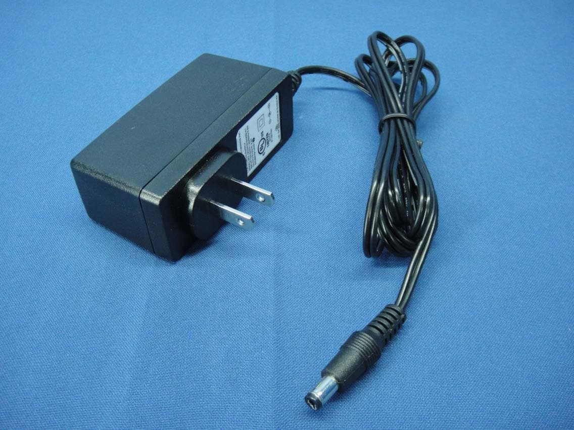
Click to zoom
Application Details
- Equipment Class
- DTS - Digital Transmission System
- Date of Grant
- Mar 17, 2015
- Application Purpose
- Original Equipment
- Date of Application
- Mar 17, 2015
- Equipment Note
- 802.11ac Router
- Frequency Range
- 5745.00000000 - 5825.00000000
- Company
- LINKSYS LLC
- Country
- United States
Documents & Files
Document Text
Text extracted from the exhibit documents filed with the FCC. Open a document above to read the original.
Users Manual
Regulatory Information WRT1200AC Table of Contents i Table of Contents Wireless Regulatory Information FCC Statement . . . . . . . . . . . . . . . . . . . . . . . . . . . . . . . . . . . . . .1 Mexico Regulatory Statement . . . . . . . . . . . . . . . . . . . . . . . . . . . . . 1 EAC Mark of Conformity for Russia, Kazakhstan and Belarus . . . . . . . . . . 1 Avis d’Industrie Canada . . . . . . . . . . . . . . . . . . . . . . . . . . . . . . . . . 2 Safety Notices . . . . . . . . . . . . . . . . . . . . . . . . . . . . . . . . . . . . . . 3 Declaration of Conformity with Regard to EU Directive 1999/5/EC (R&TTE Directive) . . . . . . . . . . . . . . . . . . . . . . . . . . . . . 7 Wireless Equipment (Wireless-AC/N/G/A/B Products) . . . . . . . . . . . . . . . 8 National Restrictions . . . . . . . . . . . . . . . . . . . . . . . . . . . . . . . . . . 8 Product Usage Restrictions . . . . . . . . . . . . . . . . . . . . . . . . . . . . . . 9 Technical Documents on www .linksys .com . . . . . . . . . . . . . . . . . . . . . .9 WEEE Information User Information for Consumer Products Covered by EU Directive 2002/96/EC on Waste Electric and Electronic Equipment (WEEE) . . . . . . 10 1 Wireless Regulatory Information Wireless Regulatory Information FCC Statement This device complies with Part 15 of the FCC Rules . Operation is subject to the following two conditions: (1) This device may not cause harmful interference, and (2) this device must accept any interference received, including interference that may cause undesired operation . This product has been tested and complies with the specifications for a Class B digital device, pursuant to Part 15 of the FCC Rules . These limits are designed to provide reasonable protection against harmful interference in a residential installation . This equipment generates, uses, and can radiate radio frequency energy and, if not installed and used according to the instructions, may cause harmful interference to radio communications . However, there is no guarantee that interference will not occur in a particular installation . If this equipment does cause harmful interference to radio or television reception, which is found by turning the equipment off and on, the user is encouraged to try to correct the interference by one or more of the following measures: •Reorient or relocate the receiving antenna •Increase the separation between the equipment and devices •Connect the equipment to an outlet other than the receiver’s •Consult a dealer or an experienced radio/TV technician for assistance FCC Caution: Any changes or modifications not expressly approved by the party responsible for compliance could void the user’s authority to operate this equipment . IEEE 802 .11b or 802 .11g operation of this product in the USA is firmware-limited to channels 1 through 11 . The device for the band 5150-5250 MHz is only for indoor usage to reduce the potential for harmful interference to co-channel mobile satellite systems . Mexico Regulatory Statement La operación de este equipo está sujeta a las siguientes dos condiciones: (1) es posible que este equipo o dispositivo no cause interferencia perjudicial y (2) este equipo o dispositivo debe aceptar cualquier interferencia, incluyendo la que pueda causar su operación no deseada . EAC Mark of Conformity for Russia, Kazakhstan and Belarus FCC Radiation Exposure Statement This equipment complies with FCC radiation exposure limits set forth for an uncontrolled environment . This equipment should be installed and operated with minimum distance 22 cm between the radiator and your body . This device and it’s antennas(s) must not be co- located or operating in conjunction with any other antenna or transmitter except in accordance with FCC multi-transmitter product procedures . Industry Canada Statement CAN ICES-3 (B)/NMB-3 (B) Operation is subject to the following two conditions: (1) This device may not cause interference, and (2) this device must accept any interference, including interference that may cause undesired operation of the device . For product available in the USA/Canada market, only channel 1~11 can be operated . Selection of other channels is not possible . The device could automatically discontinue transmission in case of absence of information to transmit, or operational failure . Note that this is not intended to prohibit transmission of control or signaling information or the use of repetitive codes where required by the technology . Industry Canada Radiation Exposure Statement This equipment complies with IC radiation exposure limits set forth for an uncontrolled environment . This equipment should be installed and operated with minimum distance 22 cm between the radiator & your body . This device and it’s antennas(s) must not be co-located or operating in conjunction with any other antenna or transmitter except in accordance with IC multi- transmitter product procedures . Restrictions in the 5 GHz Band The device for the band 5150-5250 MHz is only for indoor usage to reduce potential for harmful interference to co-channel mobile satellite systems . This device has been designed to operate with an antenna having a maximum gain of 2 .5 dBi and 3 .8 dBi at 2 .4 GHz and 5 GHz respectively . Antenna having a higher gain is strictly prohibited per regulations of Industry Canada . The required antenna impedance is 50 ohms . The maximum antenna gain (Please see the table below) permitted (for devices in the bands 5250-5350 MHz and 5470-5725 MHz) to comply with the EIRP limit and because high power radars are allocated as primary users (meaning they have priority) in 5250-5350 MHz and 2 Wireless Regulatory Information 5650-5850 MHz, these radars could cause interference and/or damage to license exempt LAN devices . No. Antenna Type For 2.4 GHz Gain (dBi) For 5 GHz Gain (dBi) Antenna Connector 1Dipole 2 .5 Band 1: 2 .6 Band 4: 3 .8 R-SMA 2Dipole 2 .5 Band 1: 2 .6 Band 4: 3 .8 R-SMA Additional requirements for the band 5600-…
Text truncated - open the document above for the full version.
Users Manual
DUAL -BAND GIGABIT Wi‑Fi ROUTER 1200AC USER GUIDE WRT 1200AC | Contents P PRODUCT OVERVIEW 1 WRT1200AC SETTING UP YOUR ROUTER 5 Where to Find More Help 5 How to Install Your Router HOW TO USE LINKSYS SMART WI-FI 6 How to Connect to Linksys Smart Wi‑Fi 6 How to Change Router Settings TROUBLESHOOTING 10 Your router was not successfully set up 11 Your Internet cable is not plugged in message 11 Cannot access your router message SPECIFICATIONS 13 Linksys WRT1200AC Contents Product Overview WRT 1200AC | Product Overview 1 Ethernet Primary Indicators Ethernet Secondary Indicators USB 2 Primary Indicator USB 2 Secondary Indicator Front Panel FRONT PANEL INDICATORS (White) The power LED is solid white while the router is powered on. It will blink when the router goes through its self‑diagnostic mode during every boot‑up. Internet (White/Amber) The Internet LED is solid white when connected to the Internet. It blinks white while the router works to establish a connection. A solid amber LED indicates the connection is down due to configuration issues. Amber blinking indicates that the connection is down due to hardware issues. 2.4 GHz (White) The Wireless LED is solid white when one or more clients are connected to the 2.4 GHz network. If the LED is blinking white, the router is sending or receiving data over the 2.4 GHz network. 5 GHz (White) The Wireless LED is solid white when one or more clients are connected to the 5GHz network. If the LED is blinking white, the router is sending or receiving data over the 5 GHz network. e SATA (White) When off, the USB/eSATA port is off or a USB device is connected. The LED is solid white when an eSATA device is connected. A blinking white LED indicates activity through the eSATA port. USB 1 (White) When off, the USB /eSATA port is off or an eSATA device is connected. The LED is solid white when a USB device is connected. A blinking white LED indicates activity on the port. USB2 Primary (White) When off, the USB 3.0 port is off. The LED is solid white when a USB device is connected. A blinking white indicates activity on the port. USB2 Secondary (White) When off, a USB 1.0 or USB 2.0 device is connected. A solid white LED indicates a USB 3.0 device is connected. ETHERNET 1 thru 4 (Primary) (White) These numbered LEDs correspond with the numbered ports on the router’s back panel. If the white LED is solid, the router is connected to a device through that port. A flashing white LED indicates network activity over that port. WRT 1200AC Front View Product Overview Product Overview 4x Adjustable External Antennas Ethernet PortsInternet PortPower Switch Wi-Fi Protected Setup Button Combo USB 2.0/ eSATA Port USB 3.0 Port Power Port Reset Button ETHERNET 1 thru 4 (Secondary) (White) If the white LED is off, the router is successfully connected to a device through that port at 10/100 Mbps. A solid white LED indicates that the router is successfully connected to a device at 1000 Mbps. (White/Amber) The LED blinks slowly for up to two minutes during Wi‑Fi Protected Setup. It will be solid white for five seconds to indicate a successful connection. The LED blinks amber if the Wi‑Fi Protected Setup process fails. Make sure the client device supports Wi‑Fi Protected Setup. Wait until the LED is off, and then try again. The router supports one session at a time. Adjustable External Antennas This router ships with two adjustable external antennas that should be connected to the router before powering it on. To connect the antennas, twist the antenna connector clockwise onto the antenna port on the router. Back View Note: For best performance, position the side antennas vertically as shown in the picture. Wi-Fi Protected Setup button Press to easily configure wireless security on Wi‑Fi Protected Setup‑enabled network devices. Ethernet Ports Connect Ethernet cables to these blue gigabit (10/ 100/ 1000) ports, and to wired devices on your network. Note: For best performance, use CAT5e or higher rated cables on the Ethernet ports. Internet Port Connect an Ethernet cable to this yellow gigabit (10/ 100/ 1000) port, and to a broadband Internet cable/DSL or fiber modem. Note: For best performance, use CAT5e or higher rated cables on the Ethernet ports. USB 3.0 Port Connect and share a USB or eSATA drive on your network or on the Internet. USB 2.0/eSATA Combo Port Connect and share a USB or eSATA drive on your network or on the Internet. You can also connect a USB printer and share it across your network. Reset Button Press and hold for 10 seconds (until the power LED starts flashing) to reset the router to factory settings. You can also restore the factory settings using Linksys Smart Wi‑Fi on the Internet or mobile app. Power Port Connect the included AC power adapter. Power Button Press to turn on the router. WRT 1200AC | Product Overview 2 Product Overview WRT 1200AC | Product Overview 3 210mm 8 1/4” 104mm 4 3/32” 105 mm Wall-Mounting Placement The router has wall‑mount slots on the bottom of each foot for flexibility in mounting the router on the wall. The distance between the slots on the short side is 105 mm. The distance between the slots on the longer side is 2 1 1 mm. Two screws are needed to mount the router. Suggested Mounting Hardware 3 mm 6-7 mm1.5-2 mm Note: Linksys is not responsible for damages incurred by unsecured wall‑mounting hardware. Mounting Instructions 1. Determine where you want to mount the router and which side you should use to mount it. Make sure that the wall you use is smooth, flat, dry, and sturdy. Make sure the location is within reach of an electrical outlet. 2. Before drilling holes, choose the template (short side or long side) that fits your installation. Drill the holes using the correct template. 3. Insert a screw into each hole and leave 4 mm of its head exposed. 4. Position the router so the wall‑mount slots line up with the two screws. 5. Place the wall‑mount slots over the screws and slide the router down until the screws fit snugly into…
Text truncated - open the document above for the full version.
Attestation Statements
Declaration for no non-US channel operation March 11, 2015 We, LINKSYS LLC declare that the device does not support channel 12 ~ 13 in 2.4GHz band and any non-US channels in all the operational mode(s) for the following product. FCC ID: Q87-WRT1200AC If you should have any question(s) regarding this declaration, please don’t hesitate to contact us. Thank you! ----------------------------------- Daniel Wesey / Director of Global Requlatory Compliance Tel: 310-751-2816 E-mail: [email protected]
Cover Letter(s)
Federal Communications Commission 7435 Oakland Mills Road Columbia MD 21046 Date: 3/10/2015 Subject: Request for Confidentiality FCC ID: Q87-WRT1200AC To Whom It May Concern: Pursuant to the provisions of Sections 0.457 and 0.459 of the Commission’s rules (47 CFR §§ 0.457, 0.459), we are requesting the Commission to withhold the following attachments as confidential document from public disclosure indefinitely. Schematic Diagram Block Diagram Theory of Operation Software Operating Description Above mentioned document contains detailed system and equipment description are considered as proprietary information in operation of the equipment. The public disclosure of above documents might be harmful to our company and would give competitor an unfair advantage in the market. In additional to above mentioned documents, pursuant to Public Notice DA 04-1705 of the Commission’s policy, in order to comply with the marketing regulations in 47 CFR §2.803 and the importation rules in 47 CFR §2.1204,while ensuring that business sensitive information remains confidential until the actual marketing of newly authorized devices. We are requesting the commission to grant short-term confidentiality request on the following attachments until 2015/6/30. External Photos Internal Photos User Manual Test Setup photos It is our understanding that all measurement test reports, FCC ID label format and correspondent during certification review process cannot be granted as confidential documents and those information will be available for public review once the grant of equipment authorization is issued. Best Regards Sincerely yours, ___________________________ Daniel Wesey / Director of Global Requlatory Compliance Tel: 310-751-2816 E-mail: [email protected] Daniel Wesey Digitally signed by Daniel Wesey DN: cn=Daniel Wesey, o=Belkin Inc.,, ou=Regulatory Compliance, [email protected], c=US Date: 2015.03.11 17:14:42 -07'00'
Cover Letter(s)
Date: 2015-03-11 FCC ID: Q87-WRT1200AC A U T H O R I Z A T I O N L E T T E R To whom it may concern: We, the undersigned, hereby authorize (name: Amanda Wu and Title: Senior Specialist)of Bureau Veritas Consumer Products Services (H.K.) Ltd., Taoyuan Branch (BV CPS Taoyuan) of Taiwan to act on our behalf in all manners relating to FCC application for equipment authorization, including signing of all documents relating to these matters. Any and all acts carried out by (name: Amanda Wu and Title: Senior Specialist) of BV CPS Taoyuan on our behalf shall have the same effect as acts of our own. If you have any questions regarding the authorization, please don’t hesitate to contact us. Sincerely yours, ----------------------------------- Daniel Wesey / Director of Global Requlatory Compliance Tel: 310-751-2816 E-mail: [email protected]
External Photos
Report No.: 141229E04 Page 1 CONSTRUCTION PHOTOS OF EUT Report No.: 141229E04 Page 2 Model No.: 2ABL030F US Report No.: 141229E04 Page 3 Report No.: 141229E04 Page 4 Model No.: MU30-5120250-A1 Report No.: 141229E04 Page 5 Report No.: 141229E04 Page 6 Model No.: MU30-P120250-A1 Report No.: 141229E04 Page 7
ID Label/Location Info
Label FCC LABEL LOCATION The label will be permanently affixed at a conspicuous location on the device. (Fig.1) FCC ID: Q87-WRT1200AC
ID Label/Location Info
REVAPPROVEDDATE REV SIZE DWG TITLE DWG NO. SCALESHEET REV A4A4 A 1/1 1 OF 1 HSINYUN LIN HSINYUN LIN 01/19/15 01/19/15 01/19/15 01/19/15 A ARELEASE TO FILE 4L-SAM2103-002 4L-SAM2103-002 DESCRIPTION REVISIONS PART NUMBER BLOCK PART NUMBER LABEL, PRODUCT,WRT1200AC, SAM2-L2LABEL, PRODUCT,WRT1200AC, SAM2-L2 SAM2-L2 WNC PROPRIETARY 20 Park Avenue II, Hsinchu Science Park, Hsinchu 308, Taiwan, R.O.C. Tel: 886-3-6667799 Fax: 886-3-5788726 SANDY CHEN SANDY CHEN REEL DIRECTION NOTES: 1. MATERIAL: WHITE MATT PET, T=0.075±0.003, FINISH: MAT COATING, T=0.025±0.003 GLUE: EMBOSSED ADHESIVE, T=0.035±0.003 2. COLOR: a. BACKGROUND= PEPER COLOR (WHITE) b. PRINTING= Linksys Horizon Blue 3. TEMPERATURE RESISTANT= 80 0 C. 4. ROLLED. R=2.0,4 PLS 100.3 30.3 +0 -0.2 +0-0.2 HTYL75(EB) Fasson:MZ0339 ONLINE PRINTING
Internal Photos
Report No.: 141229E04 Page 1 CONSTRUCTION PHOTOS OF EUT Main Source Transformers (Vendor: MINGTEK) Report No.: 141229E04 Page 2 Report No.: 141229E04 Page 3 Report No.: 141229E04 Page 4 Report No.: 141229E04 Page 5 Report No.: 141229E04 Page 6 Report No.: 141229E04 Page 7 Report No.: 141229E04 Page 8 Report No.: 141229E04 Page 9 Report No.: 141229E04 Page 10 Report No.: 141229E04 Page 11 Second Source Transformers (Vendor: BOTHHAND) Report No.: 141229E04 Page 12 Report No.: 141229E04 Page 13 Report No.: 141229E04 Page 14 Report No.: 141229E04 Page 15 Report No.: 141229E04 Page 16 Report No.: 141229E04 Page 17 Report No.: 141229E04 Page 18 Report No.: 141229E04 Page 19 Report No.: 141229E04 Page 20
RF Exposure Info
Report No.: SA141229E04 Page No. 1 / 6 Report Format Version: 6.1.1 RF Exposure Report Report No.: SA141229E04 FCC ID: Q87-WRT1200AC Test Model: WRT1200AC Received Date: Dec. 29, 2014 Test Date: Jan. 26, 2015 Issued Date: Mar. 13, 2015 Applicant: Linksys LLC Address: 121 Theory Drive Irvine California 92617 United States Issued By: Bureau Veritas Consumer Products Services (H.K.) Ltd., Taoyuan Branch Hsin Chu Laboratory Lab Address: No. 81-1, Lu Liao Keng, 9th Ling,Wu Lung Tsuen, Chiung Lin Hsiang, Hsin Chu Hsien 307, Taiwan R.O.C. Test Location (1): No. 81-1, Lu Liao Keng, 9th Ling,Wu Lung Tsuen, Chiung Lin Hsiang, Hsin Chu Hsien 307, Taiwan R.O.C. Test Location (2): No. 49, Ln. 206, Wende Rd., Shangshan Tsuen, Chiung Lin Hsiang, Hsin Chu Hsien 307, Taiwan R.O.C. This report is for your exclusive use. Any copying or replication of this report to or for any other person or entity, or use of our name or trademark, is permitted only with our prior written permission. This report sets forth our findings solely with respect to the test samples identified herein. The results set forth in this report are not indicative or representative of the quality or characteristics of the lot from which a test sample was taken or any similar or identical product unless specifically and expressly noted. Our report includes all of the tests requested by you and the results thereof based upon the information that you provided to us. You have 60 days from date of issuance of this report to notify us of any material error or omission caused by our negligence, provided, however, that such notice shall be in writing and shall specifically address the issue you wish to raise. A failure to raise such issue within the prescribed time shall constitute your unqualified acceptance of the completeness of this report, the tests conducted and the correctness of the report contents. Unless specific mention, the uncertainty of measurement has been explicitly taken into account to declare the compliance or non-compliance to the specification. The report must not be used by the client to claim product certification, approval, or endorsement by any government agencies. Report No.: SA141229E04 Page No. 2 / 6 Report Format Version: 6.1.1 Table of Contents Release Control Record .................................................................................................................................. 3 1 Certificate of Conformity ...................................................................................................................... 4 2 RF Exposure .......................................................................................................................................... 5 2.1 Limits For Maximum Permissible Exposure (MPE) ............................................................................. 5 2.2 MPE Calculation Formula ................................................................................................................... 5 2.3 Classification ....................................................................................................................................... 5 3 Calculation Result of Maximum Conducted Power ........................................................................... 6 Report No.: SA141229E04 Page No. 3 / 6 Report Format Version: 6.1.1 Release Control Record Issue No. Description Date Issued SA141229E04 Original release. Mar. 13, 2015 Report No.: SA141229E04 Page No. 4 / 6 Report Format Version: 6.1.1 1 Certificate of Conformity Product: 802.11ac Router Brand: Linksys Test Model: WRT1200AC Sample Status: ENGINEERING SAMPLE Applicant: Linksys LLC Test Date: Jan. 26, 2015 Standards: FCC Part 2 (Section 2.1091) KDB 447498 D03 IEEE C95.1 The above equipment has been tested by Bureau Veritas Consumer Products Services (H.K.) Ltd., Taoyuan Branch, and found compliance with the requirement of the above standards. The test record, data evaluation & Equipment Under Test (EUT) configurations represented herein are true and accurate accounts of the measurements of the sample’s EMC characteristics under the conditions specified in this report. Prepared by : , Date:Mar. 13, 2015 Elsie Hsu / Specialist Approved by : , Date:Mar. 13, 2015 May Chen / Manager Report No.: SA141229E04 Page No. 5 / 6 Report Format Version: 6.1.1 2 RF Exposure 2.1 Limits For Maximum Permissible Exposure (MPE) Frequency Range (MHz) Electric Field Strength (V/m) Magnetic Field Strength (A/m) Power Density (mW/cm 2 ) Average Time (minutes) Limits For General Population / Uncontrolled Exposure 300-1500 ... ... F/1500 30 1500-100,000 ... ... 1.0 30 F = Frequency in MHz 2.2 MPE Calculation Formula Pd = (Pout*G) / (4*pi*r 2 ) where Pd = power density in mW/cm 2 Pout = output power to antenna in mW G = gain of antenna in linear scale Pi = 3.1416 R = distance between observation point and center of the radiator in cm 2.3 Classification The antenna of this product, under normal use condition, is at least 22cm away from the body of the user. So, this device is classified as Mobile Device. 2.4 Antenna Gain The antennas provided to the EUT, please refer to the following table: Transmitter Circuit Brand Gain (dBi) Cable Loss (dB) Net Gain (dBi) Frequency Range (GHz to GHz) Antenna Type Connecter Type Chain (0) LINKSYS 2.5 1 1.5 2.4 ~ 2.4835 DIPOLE R-SMA2.6 1.6 1 5.15 ~ 5.25 3.8 1.9 1.9 5.725 ~ 5.85 Chain (1) LINKSYS 2.5 1 1.5 2.4 ~ 2.4835 DIPOLE R-SMA2.6 1.5 1.1 5.15 ~ 5.25 3.8 2.1 1.7 5.725 ~ 5.85 Report No.: SA141229E04 Page No. 6 / 6 Report Format Version: 6.1.1 3 Calculation Result of Maximum Conducted Power Frequency Band (MHz) Max Power (mW) Antenna Gain (dBi) Distance (cm) Power Density (mW/cm 2 ) Limit (mW/cm 2 ) 2412-2462 938.114 4.51 22 0.43571 1 5180-5240 928.803 4.06 22 0.38893 1 5745-5825 974.638 4.81 22 0.48505 1 NOTE: For 15.247 2.4GHz : Directional gain = 10 log[(10 G1/20 + 10 G2/20 ) 2 / 2] = 4.51dBi 5GHz: Directional gain = 10 log[(10 G1/20 + 10 G2/20 ) 2 / 2] = 4.81dBi For 15…
Text truncated - open the document above for the full version.
Test Report
Report No.: RF141229E04 Page No. 1 / 114 Report Format Version: 6.1.1 FCC Test Report Report No.: RF141229E04 FCC ID: Q87-WRT1200AC Test Model: WRT1200AC Received Date: Dec. 29, 2014 Test Date: Jan. 20 to Feb. 26, 2015 Issued Date: Mar. 13, 2015 Applicant: Linksys LLC Address: 121 Theory Drive Irvine California 92617 United States Issued By: Bureau Veritas Consumer Products Services (H.K.) Ltd., Taoyuan Branch Hsin Chu Laboratory Lab Address: No. 81-1, Lu Liao Keng, 9th Ling,Wu Lung Tsuen, Chiung Lin Hsiang, Hsin Chu Hsien 307, Taiwan R.O.C. Test Location (1): No. 81-1, Lu Liao Keng, 9th Ling,Wu Lung Tsuen, Chiung Lin Hsiang, Hsin Chu Hsien 307, Taiwan R.O.C. Test Location (2): No. 49, Ln. 206, Wende Rd., Shangshan Tsuen, Chiung Lin Hsiang, Hsin Chu Hsien 307, Taiwan R.O.C. This report is for your exclusive use. Any copying or replication of this report to or for any other person or entity, or use of our name or trademark, is permitted only with our prior written permission. This report sets forth our findings solely with respect to the test samples identified herein. The results set forth in this report are not indicative or representative of the quality or characteristics of the lot from which a test sample was taken or any similar or identical product unless specifically and expressly noted. Our report includes all of the tests requested by you and the results thereof based upon the information that you provided to us. You have 60 days from date of issuance of this report to notify us of any material error or omission caused by our negligence, provided, however, that such notice shall be in writing and shall specifically address the issue you wish to raise. A failure to raise such issue within the prescribed time shall constitute your unqualified acceptance of the completeness of this report, the tests conducted and the correctness of the report contents. Unless specific mention, the uncertainty of measurement has been explicitly taken into account to declare the compliance or non-compliance to the specification. The report must not be used by the client to claim product certification, approval, or endorsement by TAF or any government agencies. Report No.: RF141229E04 Page No. 2 / 114 Report Format Version: 6.1.1 Table of Contents Release Control Record .................................................................................................................................. 5 1 Certificate of Conformity ...................................................................................................................... 6 2 Summary of Test Results ..................................................................................................................... 7 2.1 Measurement Uncertainty ................................................................................................................... 7 2.2 Modification Record ............................................................................................................................ 7 3 General Information .............................................................................................................................. 8 3.1 General Description of EUT ................................................................................................................ 8 3.2 Description of Test Modes ................................................................................................................. 12 3.2.1 Test Mode Applicability and Tested Channel Detail ........................................................................... 13 3.3 Duty Cycle of Test Signal .................................................................................................................. 17 3.4 Description of Support Units ............................................................................................................. 19 3.4.1 Configuration of System under Test .................................................................................................. 20 3.5 General Description of Applied Standards ........................................................................................ 21 4 Test Types and Results (for 2.4GHz Band) ....................................................................................... 22 4.1 Radiated Emission and Bandedge Measurement ............................................................................. 22 4.1.1 Limits of Radiated Emission and Bandedge Measurement .............................................................. 22 4.1.2 Test Instruments ................................................................................................................................ 23 4.1.3 Test Procedures ................................................................................................................................. 25 4.1.4 Deviation from Test Standard ............................................................................................................ 25 4.1.5 Test Setup .......................................................................................................................................... 26 4.1.6 EUT Operating Conditions ................................................................................................................. 27 4.1.7 Test Results ....................................................................................................................................... 28 4.2 Conducted Emission Measurement .................................................................................................. 41 4.2.1 Limits of Conducted Emission Measurement .................................................................................... 41 4.2.2 Test Instruments ................................................................................................................................ 41 4.2.3 Test Procedures ...................................................................…
Text truncated - open the document above for the full version.
Test Report
Report No.: RF141229E04-1 Page No. 1 / 56 Report Format Version:6.1.1 FCC Test Report Report No.: RF141229E04-1 FCC ID: Q87-WRT1200AC Test Model: WRT1200AC Received Date: Dec. 29, 2014 Test Date: Jan. 20 to Feb. 26, 2015 Issued Date: Mar. 13, 2015 Applicant: Linksys LLC Address: 121 Theory Drive Irvine California 92617 United States Issued By: Bureau Veritas Consumer Products Services (H.K.) Ltd., Taoyuan Branch Hsin Chu Laboratory Lab Address: No. 81-1, Lu Liao Keng, 9th Ling,Wu Lung Tsuen, Chiung Lin Hsiang, Hsin Chu Hsien 307, Taiwan R.O.C. Test Location (1): No. 81-1, Lu Liao Keng, 9th Ling,Wu Lung Tsuen, Chiung Lin Hsiang, Hsin Chu Hsien 307, Taiwan R.O.C. Test Location (2): No. 49, Ln. 206, Wende Rd., Shangshan Tsuen, Chiung Lin Hsiang, Hsin Chu Hsien 307, Taiwan R…
Text truncated - open the document above for the full version.
Contact Information
Applicant
Po-Wen Cheng(Regulatory Compliance Manager)
Test Firm
Bureau Veritas CPS (H.K.) Ltd., Taoyuan BranchRichard Chen
Technical Specifications
| # | Rule Parts | Frequency Range | Power Output |
|---|---|---|---|
| 2 | 15C | 5.75 GHz - 5.83 GHz | 975.00 mW |
Other Applications from LINKSYS LLC

Q87-WDS060
Aug 11, 2020WiFi Smart Light Switch with Dimmer
Equipment Class
DTS - Digital Transmission System
Q87-03564
Jun 28, 2020Linksys Tri-Band Wireless-AC Router
Equipment Class
NII - Unlicensed National Information Infrastructure TX
Q87-03566
Jun 23, 2020Linksys Tri-Band Wireless-AC Router
Equipment Class
NII - Unlicensed National Information Infrastructure TX
Q87-03530
Apr 29, 2020Linksys MAX-STREAM AC1900+ WiFi Range Extender
Equipment Class
NII - Unlicensed National Information Infrastructure TX
Q87-08151
Mar 30, 2020Linksys Dual-Band 802.11ax Wireless Router
Equipment Class
DTS - Digital Transmission System