Q87-WRVS4400NWireless-N Gigabit Security Router with VPN
LINKSYS LLC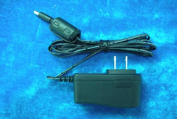
Click to zoom
Application Details
- Equipment Class
- DTS - Digital Transmission System
- Date of Grant
- Aug 08, 2006
- Application Purpose
- Original Equipment
- Date of Application
- Aug 07, 2006
- Equipment Note
- Wireless-N Gigabit Security Router with VPN
- Frequency Range
- 2412.00000000 - 2462.00000000
- Company
- LINKSYS LLC
- Country
- United States
Documents & Files
Document Text
Text extracted from the exhibit documents filed with the FCC. Open a document above to read the original.
Users Manual
Model No. Model No. USER GUIDE BUSINESS SERIES Model No. Model No. Wireless-N Gigabit Security with Ports Model No. WRVS4400N 4-portuter Router with VPN Wireless Wireless-N Gigabit Security Router with VPNCopyright and TrademarksSpecifications are subject to change without notice. L inksys is a registered trademark or trademark of Cisco Systems, Inc. and/or its affiliates in the U.S. and certain other countries. Copyright © 2006 Cisco Systems, Inc. All rights reserved. Other brands and product names are tradem arks or registered trademarks of their respective holders. How to Use this GuideThis User Guide has been designed to make understanding networking with the Router easier than ever. Look for the following items when reading this Guide:In addition to these symbols, there are definitions for technical terms that are presented like this:Also, each figure (diagram, screenshot, or other image) is provided with a figure number and description, like this:Figure numbers and descriptions can also be found in the “List of Figures” section in the “Table of Contents”. WRVS4400N-UG-50426NC RR This exclamation point means there is a caution or warning and is something that could damage your property or the Router. word: definition. This checkmark means there is a note of interest and is something you should pay special attention to while using the Router. This question mark provides you with a reminder about something you might need to do while using the Router. Figure 0-1: Sample Figure Description WARNING: This product contains chemicals, including lead, known to the State of California to cause cancer, and birth defects or other reproductive harm. Wash hands after handling. Wireless-N Gigabit Security Router with VPNTable of ContentsChapter 1: Introduction 1 Welcome 1 What’s in this Guide? 2 Chapter 2: Networking and Security Basics 4 An Introduction to LANs 4 The Use of IP Addresses 5 The Intrusion Prevent ion System (IPS) 7 Chapter 3: Planning Your Virtual Private Network (VPN) 9 Why do I need a VPN? 9 What is a VPN? 10 Chapter 4: Getting to Know the Router 12 The Front Panel 12 The Back Panels 14 Antennas and Positions 15 Chapter 5: Connecting the Router 16 Overview 16 Connection Instructions 17 Placement Options 18 Chapter 6: Setting Up and Configuring the Router 20 Overview 20 Basic Setup 20 How to Access the Web-based Utility 21 How to Navigate the Utility 21 Setup Tab 25 Wireless Tab 38 Firewall Tab 47 VPN Tab 58 QoS Tab 65 Administration Tab 67 IPS Tab 72 L2 Switch Tab 76 Status Tab 79 Appendix A: Troubleshooting 85 Wireless-N Gigabit Security Router with VPN Common Problems and Solutions 85 Frequently Asked Questions 95 Appendix B: Using the Linksys QuickVPN Software for Windows 2000 or XP 99 Overview 99 Before You Begin 99 Installing the Linksys QuickVPN Software 100 Using the Linksys Qu ickVPN Software 101 Appendix C: Configuring a Gateway-to-Gateway IPSec Tunnel 103 Overview 103 Before You Begin 103 Configuring the VPN Setti ngs for the VPN Routers 104 Configuring the Key Management Settings 106 Configuring PC 1 and PC 2 107 Appendix D: Finding the MAC Address and IP Address for Your Ethernet Adapter 108 Windows 98 or Me Instructions 108 Windows 2000 or XP Instructions 108 For the Router’s We b-based Utility 109 Appendix E: Glossary 110 Appendix F: Specifications 116 Appendix G: Warranty Information 119 Appendix H: Regulatory Information 120 Appendix I: Contact Information 126 Wireless-N Gigabit Security Router with VPNList of FiguresFigure 2-1: Example network 5 Figure 2-2: IPS Scenarios 7 Figure 3-1: VPN Router to VPN Router 11 Figure 3-2: Computer to VPN Router 11 Figure 4-1: Front Panel 12 Figure 4-2: Back Panel 14 Figure 4-3: Stackable Position and its Antenna Setup 15 Figure 4-4: Standalone Position and its Antenna Setup 15 Figure 5-1: Example of a Typical Network 16 Figure 5-2: Connect a PC 17 Figure 5-3: Connect the Internet 17 Figure 5-4: Connect the Power 17 Figure 5-5: The Stand Option 18 Figure 5-6: Stand 18 Figure 5-7: Mounting Dimensions 19 Figure 5-8: Wall Mounting Hardware 19 Figure 6-1: Router’s IP Address 21 Figure 6-2: Login Screen for Web-based Utility 21 Figure 6-1: Setup - IP Versions 25 Figure 6-2: Setup - WAN (DHCP) 26 Figure 6-3: Setup - WAN (Static IP) 26 Figure 6-4: Setup - WAN (PPPoE) 27 Figure 6-5: Setup - WAN (PPTP) 27 Figure 6-6: Setup - WAN (Heart Beat Signal) 28 Figure 6-7: Setup - WAN (L2TP) 29 Figure 6-8: Setup - WAN (Optional Settings) 30 Figure 6-9: Setup - WAN (DynDNS.org) 31 Figure 6-10: Setup - WAN (TZO.com) 31 Wireless-N Gigabit Security Router with VPNFigure 6-11: Setup - LAN 32 Figure 6-12: Setup - DMZ 34 Figure 6-13: Setup - MAC Address Clone 34 Figure 6-14: Setup - Advanced Routing 35 Figure 6-15: Setup - Advanced Routing (Routing Table) 36 Figure 6-16: Setup - Time 37 Figure 6-17: Wireless - Basic Wireless Settings 38 Figure 6-18: Wireless - Wireless Security (Disabled) 40 Figure 6-19: Wireless - Wireless Security (WPA-Personal) 40 Figure 6-20: Wireless - Wireless Security (WPA2-Personal) 41 Figure 6-21: Wireless - Wireless Security (WPA2-Personal Mixed) 41 Figure 6-22: Wireless - Wireless Security (WPA-Enterprise) 42 Figure 6-23: Wireless - Wireless Security (WPA2-Enterprise) 42 Figure 6-24: Wireless - Wireless Security (WPA2-Enterprise Mixed) 43 Figure 6-25: Wireless - Wireless Security (WEP) 43 Figure 6-26: Wireless - Wireless Connection Control 44 Figure 6-27: Select MAC Address from Wireless Client List 44 Figure 6-28: Wireless - Advanced Wireless Settings 45 Figure 6-29: Firewall - Basic Settings 47 Figure 6-30: Firewall - IP Based ACL 49 Figure 6-31: Firewall - IP Based ACL (pre-defined services) 49 Figure 6-32: Firewall - IP Based ACL (Service definition) 50 Figure 6-33: Firewall - Edit IP ACL Rule 50 Figure 6-34: Firewall - Internet Access Policy 52 Figure 6-35: Firewall - Internet Access Policy Summary 53 Figure 6-36: Firewall - Internet Access Policy (List of PCs to apply policy) 53 Figure 6-37: Firewall - Single Port Forward…
Text truncated - open the document above for the full version.
Users Manual
73 Chapter 6: Setting Up and Configuring the RouterIPS TabWireless-N Gigabit Security Router with VPNP2P/IMThis tab allows the system administrator to set up policies on using P2P or IM software across the Internet. Peer to PeerWhen users download files from the Internet by Peer to Peer (P2P) software, the WAN port bandwidth will be occupied. You can enable the blocking to the following P2P software applications. The defaults are non-block for the following applications: GNUTELLA(EZPEER), FASTTR ACK, KURO, EDONKEY2000, BITTORRECT, DIRECTCONNECT, PIGO, and WINMX. Instant MessengerUsers might use IM software to chat with friends or transferring files (bandwidth hogging). You can enable the blocking to the following IM software applications. The defaults are non-block for the following applications. MSN, ICQ, YAHOO MESSEGER, SKYPE, IRC, ODIGO, REDIFF, GOOGLE TALK, and IM QQ. Change these settings as described here and click Save Settings to apply your changes, or click Cancel Changes to cancel your changes. Help information is display ed on the right-hand side of the screen, and click More for additional details. Figure 6-60: IPS - P2P / IM 74 Chapter 6: Setting Up and Configuring the RouterIPS TabWireless-N Gigabit Security Router with VPNReportThis screen provides the network history status, including network traffic and attack counts, through diagram and tables. Report Diagram: Twenty-four hour diagram displays network traffic and attacks.AttackerDisplays the IP Address of attackers and the frequency (number of times) of the attacks in a table.Attacked CategoryDisplays the category (type) of attack and the freque ncy (number of times) of the attacks in a table. Click the View Log button to view the log. Figure 6-61: IPS - Report Figure 6-62: IPS Log Raw Data 75 Chapter 6: Setting Up and Configuring the RouterIPS TabWireless-N Gigabit Security Router with VPNInformationSignature Version . The Signature Version displays the version of the signature patterns file loaded in the Wireless Router that protects against malicious threats.Last Time Upload . This displays when the signature patterns file in the Wireless Router were last updated. Protect Scope . Displays a list of the categories of attacks that the IPS feature in the Router protects against. Those includes DoS/DDoS, Buffer Overflow, Web Attack, Scan, Trojan Horse, and IM / P2P. Figure 6-63: IPS - Information 76 Chapter 6: Setting Up and Configuring the RouterL2 Switch TabWireless-N Gigabit Security Router with VPNL2 Switch TabThe Layer 2 Switch Tab provides configurations to the layer 2 switching features on the f our Ethernet LAN ports of the Wireless Router. They include VLAN, port configur ation, cable diagnostics, and RADIUS authentication. VLANVLAN ConfigurationThe Wireless Router supports Port-based VLAN. You can ass ign each port to one of the four VLANs or VLAN Trunk. The VLAN tags are attached internally inside the switch. No packets will leave the switch with VLAN tags. VLANs are broadcast and multicast domains. Broadcast and m ulticast traffic is transmitted only within the VLAN in which the traffic is generated. The Wireless Router currently supports only one IP subnet so PCs on different VLANs cannot communicate with each other. PCs connected to the VLAN Trunk port can be accessed on all VLANs. Trunk Port . Select one of the LAN ports to accept traffic from and to all VLANs. The default is None . Change these settings as described here and click Save Settings to apply your changes, or click Cancel Changes to cancel your changes. Help information is display ed on the right-hand side of the screen, and click More for additional details. Figure 6-64: L2 Switch - VLAN 77 Chapter 6: Setting Up and Configuring the RouterL2 Switch TabWireless-N Gigabit Security Router with VPNRADIUSRADIUS mode provides authentication on devices connecting to the LAN ports. It requires installation of a RADIUS server on your local network. Mode . Select Enabled or Disabled , as desired. RADIUS IP . Enter the RADIUS server IP address. RADIUS UDP Port . Identifies the UDP port. The UDP port is used to verify the RADIUS server authentication. RADIUS Secret . Indicates the Key string used for authenticating and encrypting all RADIUS communications between the Wireless Router and the RADIUS server. This key must match the RADIUS server’s configuration. Administration State . Specifies if each port needs RA DIUS authentication. The defaults are Force Authorized so no authentication is needed. The possible field values are: • Auto . The controlled port state is set by the RADIUS Mode . • Force Authorized . The controlled port state is set to Force-Aut horized (forward traffic). All connections can be made. • Force Unauthorized . The controlled port state is set to Force-Unauthorized (discard traffic). All connections are blocked. Parameters button. Click this button to configure RADIUS re-authentication and timeout period for re-authentication and EAP. Change these settings as described here and click Save Settings to apply your changes, or click Cancel Changes to cancel your changes. Help information is display ed on the right-hand side of the screen, and click More for additional details. Figure 6-65: L2 Switch - RADIUS Figure 6-66: L2 Switch - RADIUS 78 Chapter 6: Setting Up and Configuring the RouterL2 Switch TabWireless-N Gigabit Security Router with VPNPort SettingsPort . Specifies the number of the four LAN ports. Link . Displays the port duplex mode (Full or Half) and speed (10/100/1000 Mbps). Full indicates that the interface supports transmission between the device and its link partner in both directions simultaneously. Half indicates that the interface supports transmission between the dev ice and the client in only one direction at a time. Mode . Specifies port duplex mode (Full or Half) and speed (10/100/1000 Mbps). Auto Negotiation is a protocol between two link partners that enables a port to advertise its transmission rate, duplex mode…
Text truncated - open the document above for the full version.
Users Manual
123 Appendix H: Regulatory InformationWireless-N Gigabit Security Router with VPN 124 Appendix H: Regulatory InformationWireless-N Gigabit Security Router with VPN 125 Appendix H: Regulatory InformationWireless-N Gigabit Security Router with VPNFor more information, visit www.linksys.com. 126 Appendix I: Contact InformationWireless-N Gigabit Security Router with VPNAppendix I: Contact InformationNeed to contact Linksys?Visit us online for information on the latest products and updates to your existing products at: http://www.linksys.com or ftp.linksys.com Can't find information about a product you want to buyon the web? Do you want to know more about networkingwith Linksys products? Give our advi ce line a call at: 800-546-5797 (LINKSYS) Or fax your request in to: 949-823-3002 If you experience problems with any Linksys product,you can call us at: 800-326-7114 Don't wish to call? You can e-mail us at: [email protected] If any Linksys product proves defective during its warranty period,you can call the Linksys Return Merchandise Authorizationdepartment for obtaining a Return Authorization Number at: 949-823-3000 (Details on Warranty and RMA issues can be found in the WarrantyInformation section in this Guide.)
Cover Letter(s)
Cisco-Linksys LLC 121 Theory Drive Irvine, CA 92717 (USA) Phone:949-26-1288 Fax:949-823-3002 Date: 2006/7/26 FCC ID: Q87-WRVS4400N Federal Communications Commission Authorization and Evaluation Division Confidentiality Request Pursuant to Sections 0.457 and 0.459 of the Commission’s Rules ,the Applicant hereby requests confidential treatment of information accompanying this Application as outlined below: Schematic Block Diagram Theory of Operation The above materials contain trade secrets and proprietary information not customarily released to the public. The public disclosure of these matters might be harmful to the Applicant and provide unjustified benefits to its competitors. The Applicant understands that pursuant to Rule 0.457, disclosure of this Application and all accompanying documentation will not be made before the date of the Grant for this application. Sincerely yours, Jennifer Yu/Associate Engineer Cisco-Linksys LLC Tel: (949)823-3188 Fax: (949)823-3002 [email protected]
Cover Letter(s)
Cisco-Linksys LLC 121 Theory Drive Irvine, CA 92717 (USA) Phone:949-26-1288 Fax:949-823-3002 Date: 2006/7/26 FCC ID: Q87-WRVS4400N Federal Communications Commission Authorization and Evaluation Division Subject: Short-term confidentiality request regarding application for certification of FCC ID: Q87-WRVS4400N To Whom It May Concern: Pursuant to DA 04-1705 of the Commission’s public notice, we request short-term Confidential treatment for the following information until 45 days after the Grant Date of Equipment Authorization in order to ensure sensitive business information remains confidential until the actual marketing of the device: External Photos Internal Photos Test Setup Photos User Manual Sincerely yours, Jennifer Yu/Associate Engineer Cisco-Linksys LLC Tel: (949)823-3188 Fax: (949)823-3002 [email protected]
Cover Letter(s)
Helen Zhao Subject: FW: Cisco-Linksys LLC, FCC ID: Q87-WRVS4400N, Assessment NO.: AN06T6013, Notice#1 8/8/2006 From: Lansing.li To: Helen Zhao Cc: [email protected] Subject: RE: Cisco-Linksys LLC, FCC ID: Q87-WRVS4400N, Assessment NO.: AN06T6013, Notice#1 Hello Helen, Please find our replies below in Red, Thanks!! Lansing Li / 李雪蘭 Compliance Certification Services (Kunshan) Inc. From: Lansing.li [mailto:[email protected]] Sent: Friday, August 04, 2006 4:51 PM To: 'Helen Zhao'; '[email protected]' Subject: RE: Cisco-Linksys LLC, FCC ID: Q87-WRVS4400N, Assessment NO.: AN06T6013, Notice#1 Question #1: Please submit block diagram and schematic diagram of the module: WMIM-205GN. (Lansisg: Please find our updated Block Diagram &Schematics for module attached) Question #2: The antenna spec shows antenna gain w/o cable loss is 1.8dBi, cable loss is 0.9 dBi, please explain why antenna gain listed on the test report is 3.6dBi. Please provide the formula used to calculate legacy mode antenna gain. (Lansisg: please see the "stand positon 2.4GHz "from page 10) Question #3: The test report does not show whether investigation has been performed to determine the worst case as indicated in section 3.5. If the answer is yes, please provide a clear description on various mode of operations have been investigated during the prelimiary tests. (Lansing: from question #3 to question #9, please refer to the test report.) Question #4: Test report - section 3.5, 802.11g 40MHz legacy mode (when the EUT is talking with a device without MIMO capability) was never investigated. Please explain why this test mode can be waived. Please provide test data for 802.11g 40MHz legacy mode. Question #5: Test report - section 3.5 indicates - draft 802.11n 40MHz channel mode: channel low (2432MHz) and channel high (2442MHz) ... were chosen for full testing. Based upon operation description, draft 802.11n 20MHz channel mode: channel operation frequency starting from 2412MHz; draft 802.11n 40MHz channel mode: channel operation frequency starting from 2422MHz. Please explain draft 802.11n 40MHz channel mode: why channel low (2422MHz), channel middle (2437MHz) and channel high (2452MHz) were not selected for full testing. Please redo draft 802.11n 40MHz channel mode to test at channel low (2422MHz), channel middle (2437MHz) and channel high (2452MHz). Question #6: Test report - section 6dB bandwidth page 15-17: please check the plots again, are they 6dB bandwidth or 11-12 dB bandwidth plots? page 18-20: please check the plots again, are they 6dB bandwidth or 1-2 dB bandwidth plots? Only page 21-23 are correct plots. page 24-25, please check the plots again, are they 6dB bandwidth or 1-2 dB bandwidth plots? Question #7: Test Report - section 7.3 Peak Power Output: please provide the formula used to calculate combined power output. Question #8: Test Report - section 7.4 Average Power Output : please provide the formula used to calculate combined power output. Question #9: Test Report - section 7.5 Peak Power Spectral Density : please provide the result of combined PPSD Please also provide the formula used to calculate combined PPSD . Question #10: What kind of modifications were made is questionable based on internal photos. This test sample in the internal photos is not a production sample, the deviation between the test sample and final production sample is hard to determine. Please immediately submit a test unit for sampling test. The grant can not be issued before it passes sampling test. (Lansisg: Please find our updated Intphoto) Best Regards, Helen Zhao The items indicated above must be submitted before processing can continue on the above referenced application. Failure to provide the requested information within 30 days of the original e-mail date may result in application dismissal and forfeiture of the filing fee. Also, please note that partial responses increase processing time and should not be submitted. Any questions about the content of this correspondence should be directed to the e-mail address listed below the name of the sender. 8/8/2006
Cover Letter(s)
Cisco-Linksys LLC 121 Theory Drive Irvine, CA 92617 (USA) Phone: 949-261-1288 Fax: 949-823-3002 Date:6-8-2006 Compliance Certification Services Certification Division 561F Monterey Road Morgan Hill, CA 95037 To whom it may concern: We, the undersigned, hereby authorize the Kunshan office of Compliance Certification Services Inc., d.b.a. Compliance Certification Services and hereafter referred to as CCS KS, to act on our behalf in all manners relating to application for equipment authorization, including signing of all documents relating to these matters. Any and all acts carried out by CCS KS on our behalf shall have the same effect as acts of our own. In authorizing CCS KS as our agent, we still recognize that we are responsible to: a) comply with the relevant provisions of the certification program; b) make all necessary arrangements for the conduct of the evaluation, including provision for examining documentation and access to all areas, records (including internal audit reports) and personnel for the purposes of evaluation (e.g. testing, inspection, assessment, surveillance, reassessment) and resolution of complaints; c) make claims regarding certification only in respect of the scope for which certification has been granted; d) do not use our product certification in such a manner as to bring the Certification Division into disrepute and not make any statement regarding our product certification which the Certification Division may consider misleading or unauthorized; e) upon suspension or cancellation of certification, discontinue use of all advertising matter that contains any reference thereto and return any certification documents as required by the Certification Division; f) use certification only to indicate the products are certified as being in conformity with specified standards; g) endeavor to ensure that no certificate or report nor any part thereof is used in a misleading manner; h) ensure that any reference to our product certification in communication media such as documents, brochures or advertising, complies with the requirements of the Certification Division; i) keep a record of all complaints made known to the us relating to the product抯 compliance with requirements of the relevant standard and to make these records available to the Certification Division when requested; j) take appropriate action with respect to such complaints and any deficiencies found in products or services that affect compliance with the requirements for certification; k) document the actions taken. This authorization is valid until further written notice from the applicant. Sincerely Yours, ------------------------------------------------------------------------------ Jennifer Yu Cisco-Linksys LLC Phone: 949-823-3188 Fax: 949-823-3002 [email protected]
External Photos
Compliance Certification Services (Kunshan) Inc. Report No.: KS060613A01 FCC ID: Q87-WRVS4400N Date of Issue: July 24, 2006 EXTERNAL PHOTOGRAPHS OF EUT Compliance Certification Services (Kunshan) Inc. Report No.: KS060613A01 FCC ID: Q87-WRVS4400N Date of Issue: July 24, 2006 Compliance Certification Services (Kunshan) Inc. Report No.: KS060613A01 FCC ID: Q87-WRVS4400N Date of Issue: July 24, 2006 Compliance Certification Services (Kunshan) Inc. Report No.: KS060613A01 FCC ID: Q87-WRVS4400N Date of Issue: July 24, 2006 Compliance Certification Services (Kunshan) Inc. Report No.: KS060613A01 FCC ID: Q87-WRVS4400N Date of Issue: July 24, 2006 AC to DC charger Manufactures: LINKSYS Model Number: MU12-2120100-A1
ID Label/Location Info
LABEL LOCATION
Internal Photos
Compliance Certification Services (Kunshan) Inc. Report No.: KS060613A01 FCC ID: Q87-WRVS4400N Date of Issue: July 24, 2006 INTERNAL PHOTOGRAPHS OF EUT Compliance Certification Services (Kunshan) Inc. Report No.: KS060613A01 FCC ID: Q87-WRVS4400N Date of Issue: July 24, 2006 Compliance Certification Services (Kunshan) Inc. Report No.: KS060613A01 FCC ID: Q87-WRVS4400N Date of Issue: July 24, 2006 Compliance Certification Services (Kunshan) Inc. Report No.: KS060613A01 FCC ID: Q87-WRVS4400N Date of Issue: July 24, 2006 Compliance Certification Services (Kunshan) Inc. Report No.: KS060613A01 FCC ID: Q87-WRVS4400N Date of Issue: July 24, 2006
Parts List/Tune Up Info
Specification 1. Electrical Properties : 1.1 Frequency Range..................... 1.2 Impedance ........................ ... 1.3 VSWR ................................. 1.4 Return Loss........................... 1.5 Radiation .............................. 1.6 Antenna Gain(peak)................1.8dBi (excluding cable loss) 1.7 Antenna Cable Loss............... ...0.9 dB 1.8 Polarization........................ ...Linear Vertical 1.9 Admitted Power.................. ... 2. Physical Properties : 2.1 Cable.................................1.13 Coaxial Cable 2.2 Operating Temp. .................. ...-20 ~ +65 2.3 Storage Temp. ..................... ...-30 ~ +75 2.4 Antenna Cap ..................... ...TPE 2.5 Antenna Body..................... PC 2.6 Antenna Body..................... POM 2.7 Connector........................... HRS Connector RF Antenna Cable Assembly Omni-directional 1W 2.4GHz ~ 2.5GHz 50 Nominal 1.92 Max. -10 dB Maximum 1 2 RF Antenna Assembly P/NO : C147-510263-A SPEC : 2.4GHz Antenna Dipole 1 Antenna Dipole 1 Antenna Dipole 2 Antenna Dipole 3Antenna 3 Dipole 2 Antenna Dipole 3 Antenna 4 Dipole Antenna 0 345 330 315 300 285 270 255 240 225 210 195 180 165 150 135 120 105 90 75 60 45 30 15 -20-100 dB Far-field amplitude of C147-510263-single.nsi 2.400000 GHz2.450000 GHz2.500000 GHz 5 0 345 330 315 300 285 270 255 240 225 210 195 180 165 150 135 120 105 90 75 60 45 30 15 -20-100 dB Far-field amplitude of C147-510263-single-V.nsi 2.400000 GHz2.450000 GHz2.500000 GHz 6 六Power divide Plane position stand position 7 Plane position stand position 0 345 330 315 300 285 270 255 240 225 210 195 180 165 150 135 120 105 90 75 60 45 30 15 -20-100 dB Far-field amplitude of C147-510263-P.nsi 2.400000 GHz2.450000 GHz2.500000 GHz 0 345 330 315 300 285 270 255 240 225 210 195 180 165 150 135 120 105 90 75 60 45 30 15 -20-100 dB Far-field amplitude of C147-510263-PSIT.nsi 2.400000 GHz2.450000 GHz2.500000 GHz Plane position 0 345 330 315 300 285 270 255 240 225 210 195 180 165 150 135 120 105 90 75 60 45 30 15 -20-100 dB Far-field amplitude of C147-510263-P.nsi 0 345 330 315 300 285 270 255 240 225 210 195 180 165 150 135 120 105 90 75 60 45 30 15 -20-100 dB Far-field amplitude of C147-510263-P.nsi 0 345 330 315 300 285 270 255 240 225 210 195 180 165 150 135 120 105 90 75 60 45 30 15 -20-100 dB Far-field amplitude of C147-510263-P.nsi 2.4GHz Gain = 2.39503 dBi 2.45GHz Gain = 2.17863 dBi 2.5GHz Gain = 2.07798 dBi stand position 0 345 330 315 300 285 270 255 240 225 210 195 180 165 150 135 120 105 90 75 60 45 30 15 -20-100 dB Far-field amplitude of C147-510263-PSIT.nsi 0 345 330 315 300 285 270 255 240 225 210 195 180 165 150 135 120 105 90 75 60 45 30 15 -20-100 dB Far-field amplitude of C147-510263-PSIT.nsi 0 345 330 315 300 285 270 255 240 225 210 195 180 165 150 135 120 105 90 75 60 45 30 15 -20-100 dB Far-field amplitude of C147-510263-PSIT.nsi 2.4GHz Gain = 3.67883 dBi 2.45GHz Gain = 3.17964 dBi 2.5GHz Gain = 3.21834 dBi 8 9 10 11 12
Test Report
Compliance Certification Services Inc. Report No.: KS060613A01-RP FCC ID: Q87-WRVS4400N Date of Issue: July 24, 2006 Note: This report shall not be reproduced except in full, without the written approval of Compliance Certification Services Inc. This document may be altered or revised by Compliance Certification Services Inc. personnel only, and shall be noted in the revision section of the document. Page 1 Total Page: 162 Rev. 00 FCC 47 CFR PART 15 SUBPART C TEST REPORT For Wireless-N Gigabit Security Router with VPN Model: WRVS4400N Trade Name: Linksys Issued to Cisco-Linksys LLC 121 Theory Drive Irvine, CA 92617,USA Prepared by COMPLIANCE CERTIFICATION SERVICES (KUNSHAN) INC. 10#Weiye Rd, Innovation Park Eco. & Tec. Development Zone Kunshan city JiangSu, (215300) CHINA TEL: 86-512-57355888 FAX: 86-512-57370818 Lab. Code: 200581-0 Compliance Certification Services Inc. Report No.: KS060613A01-RP FCC ID: Q87-WRVS4400N Date of Issue: July 24, 2006 Page 2 Rev. 00 TABLE OF CONTENTS 1. TEST RESULT CERTIFICATION....................................................................................................3 2. EUT DESCRIPTION ...........................................................................................................................4 3. TEST METHODOLOGY ....................................................................................................................5 3.1 EUT CONFIGURATION........................................................................................................................5 3.2 EUT EXERCISE....................................................................................................................................5 3.3 GENERAL TEST PROCEDURES.............................................................................................................5 3.4 FCC PART 15.205 RESTRICTED BANDS OF OPERATIONS.........................................................6 3.5 DESCRIPTION OF TEST MODES...........................................................................................................7 4. INSTRUMENT CALIBRATION........................................................................................................8 4.1 MEASURING INSTRUMENT CALIBRATION......................................................................................8 5. FACILITIES AND ACCREDITATIONS ..........................................................................................9 5.1 FACILITIES 9 5.2 EQUIPMENT........................................................................................................................................9 5.3 TABLE OF ACCREDITATIONS AND LISTINGS.....................................................................................10 6. SETUP OF EQUIPMENT UNDER TEST .......................................................................................11 6.1 SETUP CONFIGURATION OF EUT.......................................................................................................11 6.2 SUPPORT EQUIPMENT ...............................................................................................................11 7. FCC PART 15.247 REQUIREMENTS.............................................................................................12 7.1 6DB BANDWIDTH.............................................................................................................................12 7.2 PEAK POWER....................................................................................................................................48 7.3 AVERAGE POWER........................................................................................…
Text truncated - open the document above for the full version.
Contact Information
Applicant
Po-Wen Cheng(Regulatory Compliance Manager)
Test Firm
Compliance Certification Services (Kunshan) Inc.Eric Lin
Technical Specifications
| # | Rule Parts | Frequency Range | Power Output |
|---|---|---|---|
| 2 | 15C | 2.41 GHz - 2.46 GHz | 42.60 mW |
Other Applications from LINKSYS LLC

Q87-WDS060
Aug 11, 2020WiFi Smart Light Switch with Dimmer
Equipment Class
DTS - Digital Transmission System
Q87-03564
Jun 28, 2020Linksys Tri-Band Wireless-AC Router
Equipment Class
NII - Unlicensed National Information Infrastructure TX
Q87-03566
Jun 23, 2020Linksys Tri-Band Wireless-AC Router
Equipment Class
NII - Unlicensed National Information Infrastructure TX
Q87-03530
Apr 29, 2020Linksys MAX-STREAM AC1900+ WiFi Range Extender
Equipment Class
NII - Unlicensed National Information Infrastructure TX
Q87-08151
Mar 30, 2020Linksys Dual-Band 802.11ax Wireless Router
Equipment Class
DTS - Digital Transmission System