Q87-WT54GV40802.11G Broadband Router with SpeedBooster/Switch
LINKSYS LLC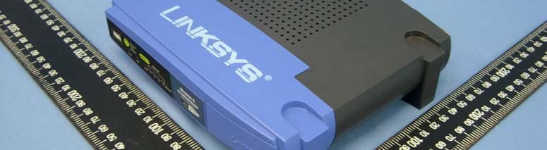
Click to zoom
Application Details
- Equipment Class
- DTS - Digital Transmission System
- Date of Grant
- May 30, 2005
- Application Purpose
- Original Equipment
- Date of Application
- May 30, 2005
- Equipment Note
- 802.11G Broadband Router with SpeedBooster/Switch
- Frequency Range
- 2412.00000000 - 2462.00000000
- Company
- LINKSYS LLC
- Country
- United States
Documents & Files
Document Text
Text extracted from the exhibit documents filed with the FCC. Open a document above to read the original.
Users Manual
A Division of Cisco Systems, Inc. ® Model No. Broadband Router Wireless-G WRT54G User Guide WIRELESS GHz 2.4 802.11g Wireless-G Broadband Router Copyright and Trademarks Specifications are subject to change without notice. Linksys is a registered trademark or trademark of Cisco Systems, Inc. and/or its affiliates in the U.S. and certain other countries. Copyright © 2005 Cisco Systems, Inc. All rights reserved. Other brands and product names are trademarks or registered trademarks of their respective holders. How to Use This User Guide This User Guide has been designed to make understanding networking with the Wireless-G Broadband Router easier than ever. Look for the following items when reading this User Guide: In addition to these symbols, there are definitions for technical terms that are presented like this: Also, each figure (diagram, screenshot, or other image) is provided with a figure number and description, like this: Figure numbers and descriptions can also be found in the “List of Figures” section in the “Table of Contents”. This exclamation point means there is a caution or warning and is something that could damage your property or the Wireless-G Broadband Router. This checkmark means there is a note of interest and is something you should pay special attention to while using the Wireless-G Broadband Router. This question mark provides you with a reminder about something you might need to do while using the Wireless-G Broadband Router. word: definition. Figure 0-1: Sample Figure Description WRT54G_V3.1-UG-50211NC JL WARNING:This product contains chemicals, including lead, known to the State of California to cause cancer, and birth defects or other reproductive harm. Wash hands after handling. Wireless-G Broadband Router Table of Contents Chapter 1: Introduction1 Welcome1 What’s in this User Guide?2 Chapter 2: Planning Your Wireless Network4 Network Topology4 Ad-Hoc versus Infrastructure Mode4 Network Layout4 Chapter 3: Getting to Know the Wireless-G Broadband Router6 The Back Panel6 The Front Panel7 Chapter 4: Connecting the Wireless-G Broadband Router8 Overview8 Hardware Installation for Connection to Your Broadband Modem8 Hardware Installation for Connection to Another Router10 Chapter 5: Setting up the Wireless-G Broadband Router12 Overview12 Using the Setup Wizard12 Using SecureEasySetup to Configure Your Notebook29 Chapter 6: Configuring the Wireless-G Broadband Router32 Overview32 The Setup Tab - Basic Setup33 The Setup Tab - DDNS37 The Setup Tab - MAC Address Clone38 The Setup Tab - Advanced Routing39 The Wireless Tab - Basic Wireless Settings40 The Wireless Tab - Wireless Security41 The Wireless Tab - Wireless MAC Filter43 The Wireless Tab - Advanced Wireless Settings44 The Security Tab - Firewall46 The Security Tab - VPN Passthrough46 The Access Restrictions Tab - Internet Access47 The Applications and Gaming Tab - Port Range Forward49 Wireless-G Broadband Router The Applications & Gaming Tab - Port Triggering50 The Applications and Gaming Tab - DMZ51 The Applications and Gaming Tab - QoS51 The Administration Tab - Management53 The Administration Tab - Log53 The Administration Tab - Diagnostics54 The Administration Tab - Factory Defaults55 The Administration Tab - Firmware Upgrade55 The Administration Tab - Config Management55 The Status Tab - Router56 The Status Tab - Local Network57 The Status Tab - Wireless58 Appendix A: Troubleshooting59 Common Problems and Solutions59 Frequently Asked Questions67 Appendix B: Wireless Security74 Security Precautions74 Security Threats Facing Wireless Networks74 Appendix C: Upgrading Firmware77 Appendix D: Windows Help78 Appendix E: Finding the MAC Address and IP Address for Your Ethernet Adapter79 Windows 98SE or Me Instructions79 Windows 2000 or XP Instructions79 For the Router’s Web-based Utility80 Appendix F: Glossary81 Appendix G: Specifications88 Appendix H: Warranty Information90 Appendix I: Regulatory Information91 Appendix J: Contact Information93 Wireless-G Broadband Router List of Figures Figure 3-1: The Router’s Back Panel6 Figure 3-2: The Router’s Front Panel7 Figure 4-1: Connecting Your Internet Connection8 Figure 4-2: Connecting Your Network Devices9 Figure 4-3: Connecting the Power9 Figure 4-4: Diagram for Connection to Another Router10 Figure 4-5: Connecting Another Router10 Figure 4-6: Connecting Your Network Devices11 Figure 4-7: Connecting the Power11 Figure 5-1: Setup Wizard’s Welcome - Language Selection Screen12 Figure 5-2: Setup Wizard’s Welcome - Start Wizard Screen12 Figure 5-3: Setup Wizard’s License Agreement Screen13 Figure 5-4: Setup Wizard’s Disconnect the Modem from the PC Screen13 Figure 5-5: Setup Wizard’s Connect the Modem to the Router Screen14 Figure 5-6: Setup Wizard’s Connect a Network Cable to a PC Screen14 Figure 5-7: Setup Wizard’s Connect the Network Cable to the Router Screen15 Figure 5-8: Setup Wizard’s Power on the Router Screen15 Figure 5-9: Setup Wizard’s Check the Router’s Status Screen16 Figure 5-10: Setup Wizard’s Configure Cable or DHCP Settings Screen16 Figure 5-11: Setup Wizard’s Configure DSL (PPPoE) Settings Screen17 Figure 5-12: Setup Wizard’s Advanced Internet Settings - Static IP Screen17 Figure 5-13: Setup Wizard’s Advanced Internet Settings - PPTP Screen18 Figure 5-14: Setup Wizard’s Keep Alive/Connect on Demand (PPTP Continued) Screen18 Figure 5-15: Setup Wizard’s Advanced Internet Settings - L2TP Screen19 Figure 5-16: Setup Wizard’s Advanced Internet Settings - Telstra Screen20 Figure 5-17: Setup Wizard’s Set the Router’s Password Screen21 Figure 5-18: Setup Wizard’s Configure Wireless Settings Screen21 Figure 5-19: Setup Wizard’s SecureEasySetup Screen22 Figure 5-20: SecureEasySetup Logo22 Figure 5-21: Additional Information - Hardware Button22 Wireless-G Broadband Router Figure 5-22: Additional Information - Software Button22 Figure 5-23: Setup Wizard’s Configure Wireless Settings Screen23 Figure 5-24: Setup Wizard’s Confirm New Settings Screen23 Figure 5-25: Setup …
Text truncated - open the document above for the full version.
Users Manual
4 Chapter 2: Planning Your Wireless Network Network Topology Wireless-G Broadband Router Chapter 2: Planning Your Wireless Network Network Topology A wireless local area network (WLAN) is exactly like a regular local area network (LAN), except that each computer in the WLAN uses a wireless device to connect to the network. Computers in a WLAN share the same frequency channel and SSID, which is an identification name shared by the wireless devices belonging to the same wireless network. Ad-Hoc versus Infrastructure Mode Unlike wired networks, wireless networks have two different modes in which they may be set up: infrastructure and ad-hoc. An infrastructure configuration is a WLAN and wired LAN communicating to each other through an access point. An ad-hoc configuration is wireless-equipped computers communicating directly with each other. Choosing between these two modes depends on whether or not the wireless network needs to share data or peripherals with a wired network or not. If the computers on the wireless network need to be accessible by a wired network or need to share a peripheral, such as a printer, with the wired network computers, the wireless network should be set up in Infrastructure mode. The basis of Infrastructure mode centers around a wireless router or an access point, such as the Wireless-G Broadband Router, which serves as the main point of communications in a wireless network. The Router transmits data to PCs equipped with wireless network adapters, which can roam within a certain radial range of the Router. You can arrange the Router and multiple access points to work in succession to extend the roaming range, and you can set up your wireless network to communicate with your Ethernet hardware as well. If the wireless network is relatively small and needs to share resources only with the other computers on the wireless network, then the Ad-Hoc mode can be used. Ad-Hoc mode allows computers equipped with wireless transmitters and receivers to communicate directly with each other, eliminating the need for a wireless router or access point. The drawback of this mode is that in Ad-Hoc mode, wireless-equipped computers are not able to communicate with computers on a wired network. And, of course, communication between the wireless- equipped computers is limited by the distance and interference directly between them. Network Layout The Wireless-G Broadband Router has been specifically designed for use with both your 802.11b and 802.11g products. Now, products using these standards can communicate with each other. infrastructure: a wireless network that is bridged to a wired network via an access point. ssid (service set identifier): your wireless network’s name. ad-hoc: a group of wireless devices communicating directly to each other (peer-to- peer) without the use of an access point. 5 Chapter 2: Planning Your Wireless Network Network Layout Wireless-G Broadband Router The Wireless-G Broadband Router is compatible with all 802.11b and 802.11g adapters, such as the Notebook Adapters (WPC54G, WPC11) for your laptop computers, PCI Adapter (WMP54G, WMP11) for your desktop PC, and USB Adapter (WUSB54G, WUSB11) when you want to enjoy USB connectivity. The Broadband Router will also communicate with the Wireless PrintServer (WPS54G) and Wireless Ethernet Bridges (WET54G, WET11). When you wish to connect your wireless network with your wired network, you can use the Wireless-G Broadband Router’s four LAN ports. To add more ports, any of the Wireless-G Broadband Router's LAN ports can be connected to any of Linksys's switches (such as the SD205 or SD208). With these, and many other, Linksys products, your networking options are limitless. Go to the Linksys website at www.linksys.com for more information about products that work with the Wireless-G Broadband Router. 6 Chapter 3: Getting to Know the Wireless-G Broadband Router The Back Panel Wireless-G Broadband Router Chapter 3: Getting to Know the Wireless-G Broadband Router The Back Panel The Router's ports, where the cables are connected, are located on the back panel. Reset ButtonThere are two ways to reset the Router's factory defaults. Either press the Reset Button, for approximately five seconds, or restore the defaults from the Administration tab - Factory Defaults in the Router's Web-based Utility. InternetThe Internet port is where you will connect your broadband Internet connection. 1, 2, 3, 4These ports (1, 2, 3, 4) connect the Router to your networked PCs and other Ethernet network devices. PowerThe Power port is where you will connect the power adapter. IMPORTANT:Resetting the Router will erase all of your settings (Internet connection, wireless security, and other settings) and replace them with the factory defaults. Do not reset the Router if you want to retain these settings. Figure 3-1: The Router’s Back Panel 7 Chapter 3: Getting to Know the Wireless-G Broadband Router The Front Panel Wireless-G Broadband Router The Front Panel The Router’s SecureEasySetup button (the Cisco logo) and LEDs are located on the front panel. (Cisco logo)Orange/White. The Cisco logo is the Router’s SecureEasySetup button. It lights up and will stay orange when the Router is powered on. The color orange indicates that the Router is not using the SecureEasySetup feature, while the color white indicates that the Router is using the SecureEasySetup feature. When the Router enters SecureEasySetup mode, the Cisco logo will turn white and start flashing. After the Router has generated the SSID and WPA-PSK (also called WPA-Personal) key, the Cisco logo will stop flashing and stay white. To clear the SSID and WPA-PSK key, press and hold down the Cisco logo for five seconds. The Cisco logo will flash slowly as the Router resets itself. The Cisco logo will turn orange to indicate a successful reset. PowerGreen. The Power LED lights up and will stay on while the Router is powered on. When the Router goes through its self-diagnostic mode during ev…
Text truncated - open the document above for the full version.
Users Manual
14 Chapter 5: Setting up the Wireless-G Broadband Router Using the Setup Wizard Wireless-G Broadband Router 6. The Setup Wizard will ask you to connect your broadband modem to the Router. After you have done so, click the Next button. 7. The Setup Wizard will ask you to connect a network cable to your PC. After you have done so, click the Next button. Figure 5-5: Setup Wizard’s Connect the Modem to the Router Screen Figure 5-6: Setup Wizard’s Connect a Network Cable to a PC Screen 15 Chapter 5: Setting up the Wireless-G Broadband Router Using the Setup Wizard Wireless-G Broadband Router 8. The Setup Wizard will ask you to connect the other end of the network cable to the Router. Then you can also connect additional PCs to the Router. After you have done so, click the Next button. 9. The Setup Wizard will ask you to power on the Router. After you have done so, click the Next button. Figure 5-7: Setup Wizard’s Connect the Network Cable to the Router Screen Figure 5-8: Setup Wizard’s Power on the Router Screen 16 Chapter 5: Setting up the Wireless-G Broadband Router Using the Setup Wizard Wireless-G Broadband Router 10. Make sure the Router’s Power, Internet, and numbered LEDs (depending on the number of PCs connected) are lit on its front panel. After you have done so, click the Next button. 11. The Setup Wizard will automatically detect the Internet connection type you use: Cable or DHCP or DSL (PPPoE). If the Setup Wizard cannot detect your Internet connection type, you will see the Advanced Internet Settings screen, and you will be asked to select your Internet connection type: Static IP, PPTP, L2TP, or Telstra. Proceed to the appropriate section for your Internet connection type. Cable or DHCP Host Name - Enter the Host Name if required by your ISP; otherwise, leave this field blank. Domain Name - Enter the Domain Name if required by your ISP; otherwise, leave this field blank. Click the Next button to continue or the Back button to return to the previous screen. Figure 5-9: Setup Wizard’s Check the Router’s Status Screen Figure 5-10: Setup Wizard’s Configure Cable or DHCP Settings Screen 17 Chapter 5: Setting up the Wireless-G Broadband Router Using the Setup Wizard Wireless-G Broadband Router DSL (PPPoE) User Name - Enter the User Name provided by your ISP. Password - Enter the Password provided by your ISP. Confirm - To confirm the Password, enter it again in this field. Keep Alive - If you want the Router to periodically check your Internet connection, select Keep Alive. Then specify how often you want the Router to check the Internet connection. If the connection is down, the Router will automatically re-establish your connection. Connect on Demand - If you want the Router to end the Internet connection after it has been inactive for a period of time, select Connect on Demand and designate the number of minutes you want that period of inactivity to last. Click the Next button to continue or the Back button to return to the previous screen. Static IP Connection - If you are required to use a permanent IP address to connect to the Internet, select Static IP from the drop-down menu. IP Address - Enter the IP address provided by your ISP. Subnet Mask- Enter the Subnet Mask provided by your ISP. Gateway - Enter the Gateway IP address provided by your ISP. DNS 1-2 - Enter the DNS (Domain Name System) server IP address(es) provided by your ISP. You need to enter at least one DNS address. Click the Next button to continue or the Back button to return to the previous screen. Figure 5-11: Setup Wizard’s Configure DSL (PPPoE) Settings Screen Figure 5-12: Setup Wizard’s Advanced Internet Settings - Static IP Screen 18 Chapter 5: Setting up the Wireless-G Broadband Router Using the Setup Wizard Wireless-G Broadband Router PPTP Connection - PPTP (Point-to-Point Tunneling Protocol) service is used in Europe only. If you are using a PPTP connection, select PPTP from the drop-down menu. User Name - Enter the User Name provided by your ISP. Password - Enter the Password provided by your ISP. Confirm - To confirm the Password, enter it again in this field. IP Address - Enter the IP address provided by your ISP. Subnet Mask- Enter the Subnet Mask provided by your ISP. Gateway - Enter the Gateway IP address provided by your ISP. Click the Next button to continue or the Back button to return to the previous screen. Keep Alive - If you want the Router to periodically check your Internet connection, select Keep Alive. Then specify how often you want the Router to check the Internet connection. If the connection is down, the Router will automatically re-establish your connection. Connect on Demand - If you want the Router to end the Internet connection after it has been inactive for a period of time, select Connect on Demand and designate the number of minutes you want that period of inactivity to last. Click the Next button to continue or the Back button to return to the previous screen. Figure 5-13: Setup Wizard’s Advanced Internet Settings - PPTP Screen Figure 5-14: Setup Wizard’s Keep Alive/Connect on Demand (PPTP Continued) Screen 19 Chapter 5: Setting up the Wireless-G Broadband Router Using the Setup Wizard Wireless-G Broadband Router L2TP Connection - If you are using an L2TP (Layer 2 Tunneling Protocol) connection, select L2TP from the drop- down menu. User Name - Enter the User Name provided by your ISP. Password - Enter the Password provided by your ISP. Confirm - To confirm the Password, enter it again in this field. L2TP Server - Enter the IP address of the L2TP server you are using; this should be provided by your ISP. Keep Alive - If you want the Router to periodically check your Internet connection, select Keep Alive. Then specify how often you want the Router to check the Internet connection. If the connection is down, the Router will automatically re-establish your connection. Connect on Demand - If you want the Router to end the Internet connection after it has been inactive for a perio…
Text truncated - open the document above for the full version.
Users Manual
24 Chapter 5: Setting up the Wireless-G Broadband Router Using the Setup Wizard Wireless-G Broadband Router 4. After the settings have been saved, the Safe Surfing screen will appear. Click the Norton Internet Security Suite button to install the special edition of Norton Internet Security on your computer, or click the Finish button to complete the Setup Wizard. 5. The Congratulations screen will appear. Click the Online Registration button to register the Router, or click the Exit button to exit the Setup Wizard. Congratulations! The installation of the Wireless-G Broadband Router is complete. If you want to make advanced configuration changes, proceed to “Chapter 6: Configuring the Wireless-G Broadband Router.” Figure 5-25: Setup Wizard’s Safe Surfing Screen Figure 5-26: Setup Wizard’s Congratulations Screen 25 Chapter 5: Setting up the Wireless-G Broadband Router Using the Setup Wizard Wireless-G Broadband Router Manually Configuring the Router’s Wireless Settings 1. If you do not have other SecureEasySetup devices, then click the Enter Wireless Settings Manually button. 2. The Setup Wizard will ask you to enter the settings for your wireless network. In the SSID field, enter the name of your wireless network. The SSID must be identical for all devices in the network. The default setting is linksys (all lowercase). Select the operating channel for your wireless network. All of your wireless devices will use this channel to communicate. From the Network Mode drop-down menu, select the wireless standards running on your network. If you have both 802.11g and 802.11b devices in your network, keep the default setting, Mixed Mode. If you have only 802.11g devices, select G-Only. If you have only 802.11b devices, select B-Only. If you want to disable your wireless network, select Disable. Enter a name for the Router in the Device Name field. Click the Next button to continue or the Back button to return to the previous screen. NOTE:An SSID is the network name shared by all devices in a wireless network. Your network’s SSID should be unique to your network and identical for all devices within the network. Figure 5-27: Setup Wizard’s Configure Wireless Settings Screen Figure 5-28: Setup Wizard’s Wireless Settings Screen 26 Chapter 5: Setting up the Wireless-G Broadband Router Using the Setup Wizard Wireless-G Broadband Router 3. Select the method of security you want to use: WPA-PSK (also called WPA-Personal), WEP (64-Bit), or WEP (128-Bit). WPA stands for Wi-Fi Protected Access, and WEP stands for Wired Equivalent Privacy. WPA is a stronger security method than WEP. Proceed to the appropriate section for your security method. If you want to use WPA-RADIUS (also called WPA-Enterprise), then you should select Disabled and use the Router’s Web-based Utility to configure your wireless security settings. Click the Next button and proceed to step 4. If you do not want to use any wireless security method, select Disabled and then click the Next button. Proceed to step 4. WPA-PSK WPA-PSK offers two encryption methods, TKIP and AES, with dynamic encryption keys. Select TKIP or AES for encryption. Then enter a Passphrase that is 8-32 characters in length. Encryption - Select the type of algorithm you want to use, TKIP or AES, from the Encryption drop-down menu. Passphrase - Enter a Passphrase, also called a pre-shared key, of 8-32 characters in the Passphrase field. The longer and more complex your Passphrase is, the more secure your network will be. Click the Next button to continue or the Back button to return to the previous screen. radius (remote authentication dial-in user service): a protocol that uses an authentication server to control network access. wep (wired equivalent privacy): a method of encrypting network data transmitted on a wireless network for greater security. wpa (wi-fi protected access: a wireless security protocol using TKIP (Temporal Key Integrity Protocol) encryption, which can be used in conjunction with a RADIUS server. encryption: encoding data transmitted in a network. Figure 5-29: Setup Wizard’s Wireless Security - WPA-PSK Screen 27 Chapter 5: Setting up the Wireless-G Broadband Router Using the Setup Wizard Wireless-G Broadband Router WEP (64-Bit) Enter a passphrase or WEP key. Passphrase - Enter a passphrase in the Passphrase field, so a WEP key is automatically generated. The passphrase is case-sensitive and should not be longer than 16 alphanumeric characters. It must match the passphrase of your other wireless network devices and is compatible with Linksys wireless products only. (If you have any non-Linksys wireless products, enter the WEP key manually on those products.) WEP Key - The WEP key you enter must match the WEP key of your wireless network. For 64-bit encryption, enter exactly 10 hexadecimal characters. Valid hexadecimal characters are “0” to “9” and “A” to “F”. Click the Next button to continue or the Back button to return to the previous screen. WEP (128-Bit) Enter a passphrase or WEP key. Passphrase - Enter a passphrase in the Passphrase field, so a WEP key is automatically generated. The passphrase is case-sensitive and should not be longer than 16 alphanumeric characters. It must match the passphrase of your other wireless network devices and is compatible with Linksys wireless products only. (If you have any non-Linksys wireless products, enter the WEP key manually on those products.) WEP Key - The WEP key you enter must match the WEP key of your wireless network. For 128-bit encryption, enter exactly 26 hexadecimal characters. Valid hexadecimal characters are “0” to “9” and “A” to “F”. Click the Next button to continue or the Back button to return to the previous screen. 4. The Setup Wizard will ask you to review your settings before it saves them. Click the Yes button if you are satisfied with your settings, or click the No button if you do not want to save your new settings. Figure 5-30: Setup Wizard’s Wireless Security - WEP (64-Bit) Screen Fig…
Text truncated - open the document above for the full version.
Users Manual
34 Chapter 6: Configuring the Wireless-G Broadband Router The Setup Tab - Basic Setup Wireless-G Broadband Router •PPPoE. Some DSL-based ISPs use PPPoE (Point-to-Point Protocol over Ethernet) to establish Internet connections. If you are connected to the Internet through a DSL line, check with your ISP to see if they use PPPoE. If they do, you will have to enable PPPoE. User Name and Password. Enter the User Name and Password provided by your ISP. Connect on Demand: Max Idle Time. You can configure the Router to cut the Internet connection after it has been inactive for a specified period of time (Max Idle Time). If your Internet connection has been terminated due to inactivity, Connect on Demand enables the Router to automatically re-establish your connection as soon as you attempt to access the Internet again. If you wish to activate Connect on Demand, click the radio button. In the Max Idle Time field, enter the number of minutes you want to have elapsed before your Internet connection terminates. Keep Alive Option: Redial Period. If you select this option, the Router will periodically check your Internet connection. If you are disconnected, then the Router will automatically re-establish your connection. To use this option, click the radio button next to Keep Alive. In the Redial Period field, you specify how often you want the Router to check the Internet connection. The default Redial Period is 30 seconds. •PPTP. Point-to-Point Tunneling Protocol (PPTP) is a service that applies to connections in Europe only. Specify Internet IP Address. This is the Router’s IP address, as seen from the Internet. Your ISP will provide you with the IP Address you need to specify here. Subnet Mask. This is the Router’s Subnet Mask, as seen by users on the Internet (including your ISP). Your ISP will provide you with the Subnet Mask. Gateway. Your ISP will provide you with the Gateway Address. User Name and Password. Enter the User Name and Password provided by your ISP. Connect on Demand: Max Idle Time. You can configure the Router to cut the Internet connection after it has been inactive for a specified period of time (Max Idle Time). If your Internet connection has been terminated due to inactivity, Connect on Demand enables the Router to automatically re-establish your connection as soon as you attempt to access the Internet again. If you wish to activate Connect on Demand, click the radio button. In the Max Idle Time field, enter the number of minutes you want to have elapsed before your Internet connection terminates. Keep Alive Option: Redial Period. If you select this option, the Router will periodically check your Internet connection. If you are disconnected, then the Router will automatically re-establish your connection. To use this option, click the radio button next to Keep Alive. In the Redial Period field, you specify how often you want the Router to check the Internet connection. The default Redial Period is 30 seconds. Figure 6-5: PPPoE Connection Type Figure 6-6: PPTP Connection Type 35 Chapter 6: Configuring the Wireless-G Broadband Router The Setup Tab - Basic Setup Wireless-G Broadband Router •HeartBeat Signal. HeartBeat Signal (HBS) is a service that applies to connections in Australia only. If your ISP is Telstra, then select HeartBeat Signal. User Name and Password. Enter the User Name and Password provided by your ISP. Heart Beat Server. This is the IP address that the Router has, when seen from the Internet. Your ISP will provide you with the IP Address you need to specify here. Connect on Demand: Max Idle Time. You can configure the Router to cut the Internet connection after it has been inactive for a specified period of time (Max Idle Time). If your Internet connection has been terminated due to inactivity, Connect on Demand enables the Router to automatically re-establish your connection as soon as you attempt to access the Internet again. If you wish to activate Connect on Demand, click the radio button. In the Max Idle Time field, enter the number of minutes you want to have elapsed before your Internet connection terminates. Keep Alive Option: Redial Period. If you select this option, the Router will periodically check your Internet connection. If you are disconnected, then the Router will automatically re-establish your connection. To use this option, click the radio button next to Keep Alive. In the Redial Period field, you specify how often you want the Router to check the Internet connection. The default Redial Period is 30 seconds. Optional Settings Some of these settings may be required by your ISP. Verify with your ISP before making any changes. Router Name. In this field, you can type a name of up to 39 characters to represent the Router. Host Name/Domain Name. These fields allow you to supply a host and domain name for the Router. Some ISPs, usually cable ISPs, require these names as identification. You may have to check with your ISP to see if your broadband Internet service has been configured with a host and domain name. In most cases, leaving these fields blank will work. MTU. MTU is the Maximum Transmission Unit. It specifies the largest packet size permitted for Internet transmission. The default setting, Manual, allows you to enter the largest packet size that will be transmitted. The recommended size, entered in the Size field, is 1492. You should leave this value in the 1200 to 1500 range. To have the Router select the best MTU for your Internet connection, select Auto. Network Setup The Network Setup section changes the settings on the network connected to the Router’s Ethernet ports. Wireless Setup is performed through the Wireless tab. Figure 6-8: Optional Settings Figure 6-7: HeartBeat Signal Connection Type 36 Chapter 6: Configuring the Wireless-G Broadband Router The Setup Tab - Basic Setup Wireless-G Broadband Router Router IP This presents both the Router’s IP Address and Subnet Mask as seen by your network. Network Address Server Settings (DH…
Text truncated - open the document above for the full version.
Contact Information
Applicant
Po-Wen Cheng(Regulatory Compliance Manager)
Technical Contact
Advance Data Technology CorporationEirc Lin
[email protected]886-3-593-5343
81-1 Luliaoken, 9th Lin, Wulung Tsuen Chiunglin · Hsinchu · Taiwan
Test Firm
Bureau Veritas CPS (H.K.) Ltd. Taoyuan BranchRichard Chen
Technical Specifications
| # | Rule Parts | Frequency Range | Power Output |
|---|---|---|---|
| 1 | 15C | 2.41 GHz - 2.46 GHz | 83.00 mW |
Other Applications from LINKSYS LLC

Q87-WDS060
Aug 11, 2020WiFi Smart Light Switch with Dimmer
Equipment Class
DTS - Digital Transmission System
Q87-03564
Jun 28, 2020Linksys Tri-Band Wireless-AC Router
Equipment Class
NII - Unlicensed National Information Infrastructure TX
Q87-03566
Jun 23, 2020Linksys Tri-Band Wireless-AC Router
Equipment Class
NII - Unlicensed National Information Infrastructure TX
Q87-03530
Apr 29, 2020Linksys MAX-STREAM AC1900+ WiFi Range Extender
Equipment Class
NII - Unlicensed National Information Infrastructure TX
Q87-08151
Mar 30, 2020Linksys Dual-Band 802.11ax Wireless Router
Equipment Class
DTS - Digital Transmission System