Q87-WT54GV70Wireless-G Broadband Router with 4-Port Switch
LINKSYS LLC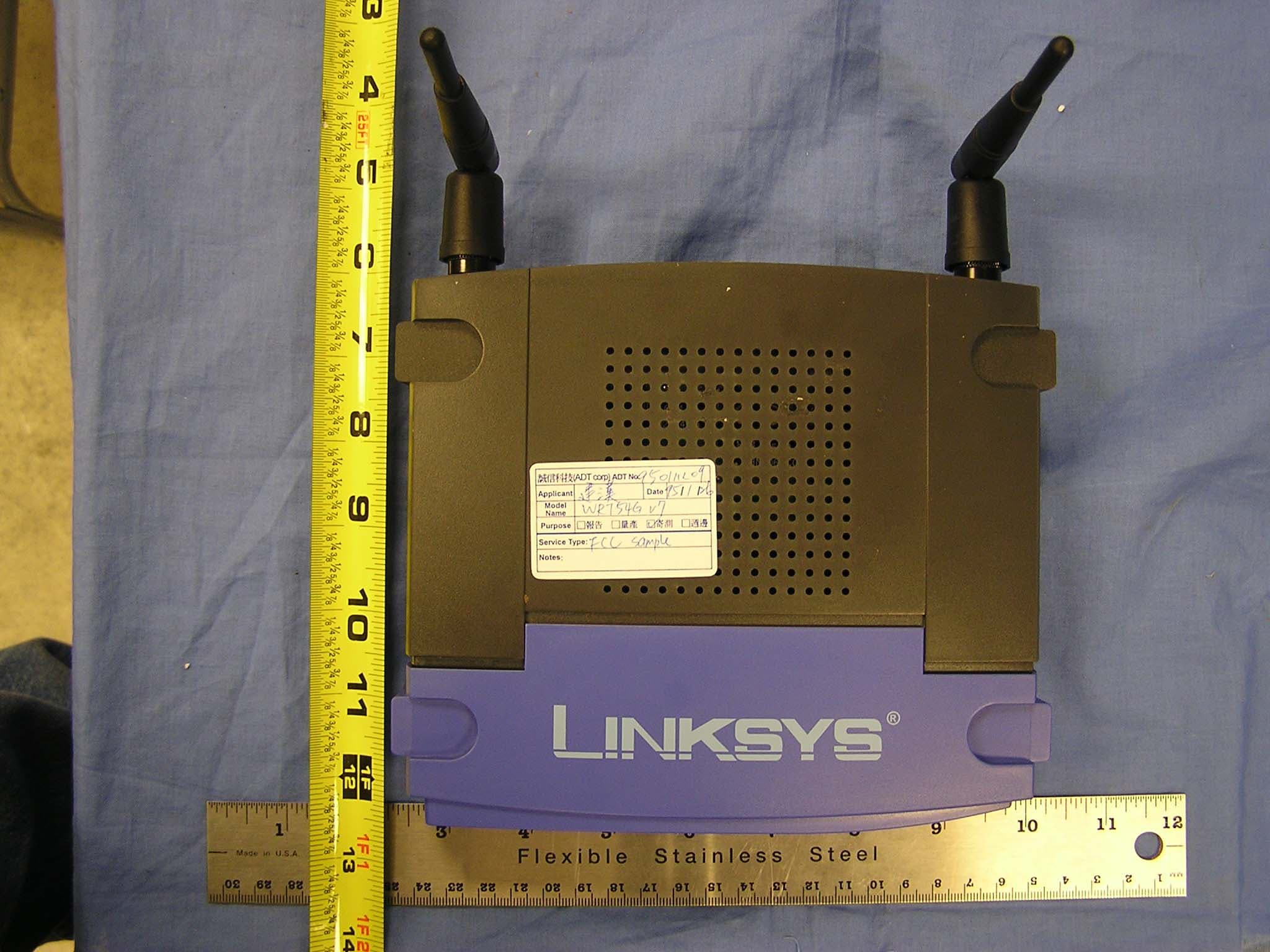
Click to zoom
Application Details
- Equipment Class
- DTS - Digital Transmission System
- Date of Grant
- Mar 07, 2006
- Application Purpose
- Original Equipment
- Date of Application
- Mar 07, 2006
- Equipment Note
- Wireless-G Broadband Router with 4-Port Switch
- Frequency Range
- 2412.00000000 - 2462.00000000
- Company
- LINKSYS LLC
- Country
- United States
Documents & Files
Document Text
Text extracted from the exhibit documents filed with the FCC. Open a document above to read the original.
Users Manual
Model No. Broadband Router Wireless-G WRT54G User Guide WIRELESS GHz 2.4 802.11g Wireless-G Broadband Router Copyright and Trademarks Specifications are subject to change without notice. Linksys is a registered trademark or trademark of Cisco Systems, Inc. and/or its affiliates in the U.S. and certain other countries. Copyright © 2006 Cisco Systems, Inc. All rights reserved. Other brands and product names are trademarks or registered trademarks of their respective holders. How to Use This User Guide This User Guide has been designed to make understanding networking with the Wireless-G Broadband Router easier than ever. Look for the following items when reading this User Guide: In addition to these symbols, there are definitions for technical terms that are presented like this: Also, each figure (diagram, screenshot, or other image) is provided with a figure number and description, like this: Figure numbers and descriptions can also be found in the “List of Figures” section in the “Table of Contents”. This exclamation point means there is a caution or warning and is something that could damage your property or the Wireless-G Broadband Router. This checkmark means there is a note of interest and is something you should pay special attention to while using the Wireless-G Broadband Router. This question mark provides you with a reminder about something you might need to do while using the Wireless-G Broadband Router. word: definition. Figure 0-1: Sample Figure Description WRT54G_V6-UG-60307 BW WARNING:This product contains chemicals, including lead, known to the State of California to cause cancer, and birth defects or other reproductive harm. Wash hands after handling. Wireless-G Broadband Router Table of Contents Chapter 1: Introduction1 Welcome1 What’s in this User Guide?2 Chapter 2: Planning Your Wireless Network4 Network Topology4 Ad-Hoc versus Infrastructure Mode4 Network Layout4 Chapter 3: Getting to Know the Wireless-G Broadband Router6 The Back Panel6 The Front Panel7 Chapter 4: Connecting the Wireless-G Broadband Router8 Overview8 Hardware Installation for Connection to Your Broadband Modem8 Hardware Installation for Connection to Another Router10 Chapter 5: Configuring the Wireless-G Broadband Router12 Overview12 The Setup Tab - Basic Setup13 The Setup Tab - DDNS18 The Setup Tab - MAC Address Clone18 The Setup Tab - Advanced Routing19 The Wireless Tab - Basic Wireless Settings20 The Wireless Tab - Wireless Security21 The Wireless Tab - Wireless MAC Filter24 The Wireless Tab - Advanced Wireless Settings25 The Security Tab - Firewall27 The Security Tab - VPN Passthrough27 The Access Restrictions Tab - Internet Access28 The Applications and Gaming Tab - Port Range Forward30 The Applications & Gaming Tab - Port Triggering31 The Applications and Gaming Tab - DMZ32 The Applications and Gaming Tab - QoS32 The Administration Tab - Management34 Wireless-G Broadband Router The Administration Tab - Log34 The Administration Tab - Diagnostics35 The Administration Tab - Factory Defaults36 The Administration Tab - Firmware Upgrade36 The Administration Tab - Config Management36 The Status Tab - Router37 The Status Tab - Local Network38 The Status Tab - Wireless39 Appendix A: Troubleshooting40 Common Problems and Solutions40 Frequently Asked Questions48 Appendix B: Wireless Security55 Security Precautions55 Security Threats Facing Wireless Networks55 Appendix C: Upgrading Firmware58 Appendix D: Windows Help59 Appendix E: Finding the MAC Address and IP Address for Your Ethernet Adapter 60 Windows 98SE or Me Instructions60 Windows 2000 or XP Instructions60 For the Router’s Web-based Utility61 Appendix F: Glossary62 Appendix G: Specifications67 Appendix H: Warranty Information69 Appendix I: Regulatory Information70 Appendix J: Contact Information76 Wireless-G Broadband Router List of Figures Figure 3-1: The Router’s Back Panel6 Figure 3-2: The Router’s Front Panel7 Figure 4-1: Connecting Your Internet Connection8 Figure 4-2: Connecting Your Network Devices9 Figure 4-3: Connecting the Power9 Figure 4-4: Diagram for Connection to Another Router10 Figure 4-5: Connecting Another Router10 Figure 4-6: Connecting Your Network Devices11 Figure 4-7: Connecting the Power11 Figure 5-1: Password Screen12 Figure 5-2: Setup Tab - Basic Setup13 Figure 5-3: DHCP Connection Type13 Figure 5-4: Static IP Connection Type13 Figure 5-5: PPPoE Connection Type14 Figure 5-6: PPTP Connection Type14 Figure 5-7: Telstra Connection Type15 Figure 5-8: L2TP Connection Type15 Figure 5-9: Optional Settings16 Figure 5-10: Router IP16 Figure 5-11: Network Address Server Settings16 Figure 5-12: Time Setting17 Figure 5-13: Setup Tab - DDNS18 Figure 5-14: Setup Tab - MAC Address Clone18 Figure 5-15: Setup Tab - Advanced Routing (Gateway)19 Figure 5-16: Setup Tab - Advanced Routing (Router)19 Figure 5-17: Wireless Tab - Basic Wireless Settings20 Figure 5-18: Wireless Tab - Wireless Security (WPA Personal)21 Figure 5-19: Wireless Tab - Wireless Security (WPA Enterprise)21 Figure 5-20: Wireless Tab - Wireless Security (WPA2 Personal)22 Figure 5-21: Wireless Tab - Wireless Security (WPA2 Enterprise)22 Figure 5-22: Wireless Tab - Wireless Security (RADIUS)23 Wireless-G Broadband Router Figure 5-23: Wireless Tab - Wireless Security (WEP)23 Figure 5-24: Wireless Tab - Wireless MAC Filter24 Figure 5-25: MAC Address Filter List24 Figure 5-26: Wireless Tab - Advanced Wireless Settings25 Figure 5-27: Security Tab - Firewall27 Figure 5-28: Security Tab - VPN Passthrough27 Figure 5-29: Access Restrictions Tab - Internet Access28 Figure 5-30: Internet Policy Summary28 Figure 5-31: List of PCs28 Figure 5-32: Port Services29 Figure 5-33: Access Restrictions Tab - Inbound Traffic29 Figure 5-34: Applications and Gaming Tab - Port Range Forward30 Figure 5-35: Applications and Gaming Tab - Port Triggering31 Figure 5-36: Applications and Gaming Tab - DMZ32 Figure 5-37: Applications and Gaming Tab - QOS32 Figure 5-38: Administration Tab - Management34 Figure …
Text truncated - open the document above for the full version.
Cover Letter(s)
Cisco-Linksys LLC 121 Theory Drive Irvine, CA 92617(USA) Phone: ( 949 ) 823-3188 Fax: ( 949 ) 823-3002 Compliance Certification Services Certification Division 561F Monterey Road Morgan Hill, CA 95037 February 16, 2006 To Whom It May Concern: We, the undersigned, hereby authorize the Testing Division of Compliance Engineering Services, Inc., d.b.a. Compliance Certification Services and hereafter referred to as CCS, to act on our behalf in all manners relating to application for equipment authorization, including signing of all documents relating to these matters. Any and all acts carried out by CCS on our behalf shall have the same effect as acts of our own. We, the undersigned, hereby certify that we are not subject to a denial of federal benefits, that includes FCC benefits, pursuant to Section 5301 of the Anti-Drug Abuse Act of 1988, 21 U.S.C. 853(a). In authorizing CCS Testing Division as our agent, we still recognize that we are responsible to: a ) comply with the relevant provisions of the certification program; b) make all necessary arrangements for the conduct of the evaluation, including provision for examining documentation and access to all areas, records (including internal audit reports) and personnel for the purposes of evaluation (e.g. testing, inspection, assessment, surveillance, reassessment) and resolution of complaints; c) make claims regarding certification only in respect of the scope for which certification has been granted; d) not use our product certification in such a manner as to bring the Certification Division into disrepute and not make any statement regarding our product certification which the Certification Division may consider misleading or unauthorized; e) upon suspension or cancellation of certification, discontinue use of all advertising matter that contains any reference thereto and return any certification documents as required by the Certification Division; f) use certification only to indicate the products are certified as being in conformity with specified standards; g) endeavor to ensure that no certificate or report nor any part thereof is used in a misleading manner; h) ensure that any reference to our product certification in communication media such as documents, brochures or advertising, complies with the requirements of the Certification Division; i) keep a record of all complaints made known to the us relating to the product’s compliance with requirements of the relevant standard and to make these records available to the Certification Division when requested; j) take appropriate action with respect to such complaints and any deficiencies found in products or services that affect compliance with the requirements for certification; k) document the actions taken. This authorization is valid until further written notice from the applicant. Sincerely, Jennifer Yu / Associate Engineer Cisco-Linksys LLC Phone: 949-823-3188 Fax: 949-823-3002 [email protected]
Cover Letter(s)
Cisco-Linksys LLC 121 Theory Drive Irvine, CA 92617(USA) Phone: ( 949 ) 823-3188 Fax: ( 949 ) 823-3002 Federal Communications Commission Authorization and Evaluation Division Confidentiality Request FCC ID: Q87-WT54GV70 Pursuant to Sections 0.457 and 0.459 of the Commission’s Rules, the Applicant hereby requests confidential treatment of information accompanying this Application as outlined below: Schematics Block Diagram Antenna Spec The above materials contain trade secrets and proprietary information not customarily released to the public. The public disclosure of these matters might be harmful to the Applicant and provide unjustified benefits to its competitors. The Applicant understands that pursuant to Rule 0.457, disclosure of this Application and all accompanying documentation will not be made before the date of the Grant for this application. Sincerely yours, ------------------------------------------------------------------------------ Jennifer Yu / Associate Engineer Cisco-Linksys LLC Phone: 949-823-3188 Fax: 949-823-3002 [email protected]
Cover Letter(s)
1 Helen Zhao Subject: FW: answer: Cisco-Linksys, LLC, FCC ID: Q87-WT54GV70, Assessment NO.: AN06T5542, Notice#1 User Manual(revised).pd f WRT54GV7_FCC_C onfidential Lett... WRT54GV7_Schem atics.pdf -----Original Message----- From: Claire Hoque Sent: Wednesday, March 08, 2006 9:52 AM To: Helen Zhao Subject: answer: Cisco-Linksys, LLC, FCC ID: Q87-WT54GV70, Assessment NO.: AN06T5542, Notice#1 Hi Helen, Pls see my answers below. Question #1: The test report indicates the device uses Atheros RF chipset, but the schematics does not show the RF chipset. Please confirm if the schematic diagram is complete. The operational description does not contain enough information as name of the RF chipset either. Please update the documents. <answer>pls see revised schematic to include Ahteros RF chipset. The operational description is deleted from confidentiality letter. Question #2: The user manual does not contain user information as required by FCC15.21, and non-colocation restriction statement as required by FCC15.247(i). Please update the user manual. <answer>pls see updated manual(page 76). Question #3: The user manual indicates 11 available channels in US and Canada, 13 available channels in EU, please state clearly how you make certain that unauthorized channels will be not used in US. <answer>The way this works is that the device firmware will read the domain/country code information that's stored in the Flash to indicate the region of which the device is shipped into. This value is programmed during manufacturing time and cannot be altered by the end user. Firmware will limit the number of channels that the device can operate in base on this domain/country code. Furthermore, the web user interface will also limit the channels that a user can select. Thanks, Claire > The items indicated above must be submitted before processing can continue on the above referenced application. Failure to provide the requested information within 30 days of the original e-mail date may result in application dismissal and forfeiture of the filing fee. Also, please note that partial responses increase processing time and should not be submitted. Any questions about the content of this correspondence 2 should be directed to the e-mail address listed below the name of the sender. > >
ID Label/Location Info
FCC Label location Product Label FCC Label
Operational Description
FCC ID: Q87-WT54GV70
Test Report
FCC CFR47 PART 15 SUBPART C CERTIFICATION TEST REPORT FOR WIRELESS-G BROADBAND ROUTER WITH 4-PORT SWITCH MODEL NUMBER: WRT54G v7 FCC ID: Q87-WT54GV70 REPORT NUMBER: 06U10091-1 ISSUE DATE: FEBRUARY 21, 2006 Prepared for CISCO-LINKSYS LLC 121 THEORY DRIVE CITY IRVINE, CA. 92617 Prepared by COMPLIANCE CERTIFICATION SERVICES 561F MONTEREY ROAD, MORGAN HILL, CA 95037, USA TEL: (408) 463-0885 FAX: (408) 463-0888 REPORT NO: 06U10091-1 DATE: FEBRUARY 21, 2005 EUT: WIRELESS-G BROADBAND ROUTER WITH 4-PORST SWITCH FCC ID: Q87-WT54GV70 Page 2 of 94 COMPLIANCE CERTIFICATION SERVICES DOCUMENT NO: CCSUP4031A 561F MONTEREY ROAD, MORGAN HILL, CA 95037 USA TEL: (408) 463-0885 FAX: (408) 463-0888 This report shall not be reproduced except in full, without the written approval of CCS. Revision History Rev. Issue Date Revisions Revised By A 2/15/2006 Initial Issue Thu Chan REPORT NO: 06U10091-1 DATE: FEBRUARY 21, 2005 EUT: WIRELESS-G BROADBAND ROUTER WITH 4-PORST SWITCH FCC ID: Q87-WT54GV70 Page 3 of 94 COMPLIANCE CERTIFICATION SERVICES DOCUMENT NO: CCSUP4031A 561F MONTEREY ROAD, MORGAN HILL, CA 95037 USA TEL: (408) 463-0885 FAX: (408) 463-0888 This report shall not be reproduced except in full, without the written approval of CCS. TABLE OF CONTENTS 1. ATTESTATION OF TEST RESULTS............................................................................................. 4 2. TEST METHODOLOGY .................................................................................................................. 5 3. FACILITIES AND ACCREDITATION .......................................................................................... 5 4. CALIBRATION AND UNCERTAINTY.......................................................................................... 5 4.1. MEASURING INSTRUMENT CALIBRATION ............................................................................. 5 4.2. MEASUREMENT UNCERTAINTY ............................................................................................... 5 5. EQUIPMENT UNDER TEST............................................................................................................6 5.1. DESCRIPTION OF EUT ..............................................................................................................6 5.2. MAXIMUM OUTPUT POWER .................................................................................................... 6 5.3. DESCRIPTION OF AVAILABLE ANTENNAS ............................................................................. 6 5.4. SOFTWARE AND FIRMWARE .................................................................................................... 6 5.5. WORST-CASE CONFIGURATION AND MODE......................................................................... 6 5.6. DESCRIPTION OF TEST SETUP ................................................................................................ 7 6. TEST AND MEASUREMENT EQUIPMENT ................................................................................ 9 7. LIMITS AND RESULTS ................................................................................................................. 10 7.1. CHANNEL TESTS FOR THE 2400 TO 2483.5 MHz BAND ...................................................... 10 7.1.1. 6 dB BANDWIDTH ........................................................................................................... 10 7.1.2. 99% BANDWIDTH............................................................................................................ 17 7.1.3. PEAK OUTPUT POWER .................................................................................................. 24 7.1.4. MAXIMUM PERMISSIBLE EXPOSURE ........................................................................ 32 7.1.5. AVERAGE POWER........................................................................................................... 35 7.1.6. PEAK POWER SPECTRAL DENSITY ............................................................................ 36 7.1.7. CONDUCTED SPURIOUS EMISSIONS.......................................................................... 43 7.2. RADIATED EMISSIONS.............................................................................................................56 7.2.1. TRANSMITTER RADIATED SPURIOUS EMISSIONS ................................................. 56 7.2.2. TRANSMITTER ABOVE 1 GHz FOR 2400 TO 2483.5 MHz BAND ............................. 59 7.2.3. WORST-CASE RADIATED EMISSIONS BELOW 1 GHz ............................................. 82 7.3. POWERLINE CONDUCTED EMISSIONS ................................................................................ 86 8. SETUP PHOTOS .............................................................................................................................. 90 REPORT NO: 06U10091-1 DATE: FEBRUARY 21, 2005 EUT: WIRELESS-G BROADBAND ROUTER WITH 4-PORST SWITCH FCC ID: Q87-WT54GV70 Page 4 of 94 COMPLIANCE CERTIFICATION SERVICES DOCUMENT NO: CCSUP4031A 561F MONTEREY ROAD, MORGAN HILL, CA 95037 USA TEL: (408) 463-0885 FAX: (408) 463-0888 This report shall not be reproduced except in full, without the written approval of CCS. 1. ATTESTATION OF TEST RESULTS COMPANY NAME: CISCO-LINKSYS LLC 121 THEORY DRIVE IRVINE, CA. 92617 EUT DESCRIPTION: WIRELESS-G BROADBAND ROUTER WITH 4-PORT SWITCH MODEL: WRT54G v7 SERIAL NUMBER: 00011 DATE TESTED: FEBRUARY 13-15, 2006 APPLICABLE STANDARDS STANDARD TEST RESULTS FCC PART 15 SUBPART C NO NON-COMPLIANCE NOTED Compliance Certification Services, Inc. tested the above equipment in accordance with the requirements set forth in the above standards. The test results show that the equipment tested is capable of demonstrating compliance with the requirements as documented in this report. Note: The results documented in this report apply only to the tested sample, under the conditions and modes of operation as described herein. This document may not be altered or revised in any way unless done so by Compli…
Text truncated - open the document above for the full version.
Test Setup Photos
REPORT NO: 06U10091-1 DATE: FEBRUARY 21, 2005 EUT: WIRELESS-G BROADBAND ROUTER WITH 4-PORST SWITCH FCC ID: Q87-WT54GV70 Page 90 of 94 COMPLIANCE CERTIFICATION SERVICES DOCUMENT NO: CCSUP4031A 561F MONTEREY ROAD, MORGAN HILL, CA 95037 USA TEL: (408) 463-0885 FAX: (408) 463-0888 This report shall not be reproduced except in full, without the written approval of CCS. 8. SETUP PHOTOS ANTENNA PORT CONDUCTED RF MEASUREMENT SETUP ANTENNA PORT CONDUCTED PHOTO REPORT NO: 06U10091-1 DATE: FEBRUARY 21, 2005 EUT: WIRELESS-G BROADBAND ROUTER WITH 4-PORST SWITCH FCC ID: Q87-WT54GV70 Page 91 of 94 COMPLIANCE CERTIFICATION SERVICES DOCUMENT NO: CCSUP4031A 561F MONTEREY ROAD, MORGAN HILL, CA 95037 USA TEL: (408) 463-0885 FAX: (408) 463-0888 This report shall not be reproduced except in full, without the written approval of CCS. RADIATED RF MEASUREMENT SETUP RADIATED FRONT PHOTO REPORT NO: 06U10091-1 DATE: FEBRUARY 21, 2005 EUT: WIRELESS-G BROADBAND ROUTER WITH 4-PORST SWITCH FCC ID: Q87-WT54GV70 Page 92 of 94 COMPLIANCE CERTIFICATION SERVICES DOCUMENT NO: CCSUP4031A 561F MONTEREY ROAD, MORGAN HILL, CA 95037 USA TEL: (408) 463-0885 FAX: (408) 463-0888 This report shall not be reproduced except in full, without the written approval of CCS. RADIATED BACK PHOTO REPORT NO: 06U10091-1 DATE: FEBRUARY 21, 2005 EUT: WIRELESS-G BROADBAND ROUTER WITH 4-PORST SWITCH FCC ID: Q87-WT54GV70 Page 93 of 94 COMPLIANCE CERTIFICATION SERVICES DOCUMENT NO: CCSUP4031A 561F MONTEREY ROAD, MORGAN HILL, CA 95037 USA TEL: (408) 463-0885 FAX: (408) 463-0888 This report shall not be reproduced except in full, without the written approval of CCS. POWERLINE CONDUCTED EMISSIONS MEASUREMENT SETUP LINE CONDUCTED FRONT PHOTO REPORT NO: 06U10091-1 DATE: FEBRUARY 21, 2005 EUT: WIRELESS-G BROADBAND ROUTER WITH 4-PORST SWITCH FCC ID: Q87-WT54GV70 Page 94 of 94 COMPLIANCE CERTIFICATION SERVICES DOCUMENT NO: CCSUP4031A 561F MONTEREY ROAD, MORGAN HILL, CA 95037 USA TEL: (408) 463-0885 FAX: (408) 463-0888 This report shall not be reproduced except in full, without the written approval of CCS. END OF REPORT LINE CONDUCTED BACK PHOTO
Contact Information
Applicant
Po-Wen Cheng(Regulatory Compliance Manager)
Test Firm
Compliance Certification Services IncSteve Cheng
Technical Specifications
| # | Rule Parts | Frequency Range | Power Output |
|---|---|---|---|
| 1 | 15C | 2.41 GHz - 2.46 GHz | 237.00 mW |
Other Applications from LINKSYS LLC

Q87-WDS060
Aug 11, 2020WiFi Smart Light Switch with Dimmer
Equipment Class
DTS - Digital Transmission System
Q87-03564
Jun 28, 2020Linksys Tri-Band Wireless-AC Router
Equipment Class
NII - Unlicensed National Information Infrastructure TX
Q87-03566
Jun 23, 2020Linksys Tri-Band Wireless-AC Router
Equipment Class
NII - Unlicensed National Information Infrastructure TX
Q87-03530
Apr 29, 2020Linksys MAX-STREAM AC1900+ WiFi Range Extender
Equipment Class
NII - Unlicensed National Information Infrastructure TX
Q87-08151
Mar 30, 2020Linksys Dual-Band 802.11ax Wireless Router
Equipment Class
DTS - Digital Transmission System