Q87-WUSB11V3Linksys Wireless-B USB Network Adapter v3.0
LINKSYS LLC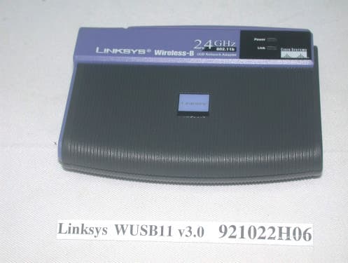
Click to zoom
Application Details
- Equipment Class
- DTS - Digital Transmission System
- Date of Grant
- Oct 27, 2003
- Application Purpose
- Original Equipment
- Date of Application
- Oct 27, 2003
- Equipment Note
- Linksys Wireless-B USB Network Adapter v3.0
- Frequency Range
- 2412.00000000 - 2462.00000000
- Company
- LINKSYS LLC
- Country
- United States
Documents & Files
Document Text
Text extracted from the exhibit documents filed with the FCC. Open a document above to read the original.
Users Manual
Linksys Wireless-B USB Network Adapter v3.0 User’s Manual Rev Draft USB Wireless Network Adapter User’s Manual 2 Regulatory compliance FCC Warning This equipment has been tested and found to comply with the limits for a Class B digital device, pursuant to part 15 of the FCC Rules. These limits are designed to provide reasonable protection against harmful interference in a residential installation. This equipment generates, uses and can radiate radio frequency energy and, if not installed and used in accordance with the instructions, may cause harmful interference to radio communications. However, there is no guarantee that interference will not occur in a particular installation. If this equipment does cause harmful interference to radio or television reception, which can be determined by turning the equipment off and on, the user is encouraged to try to correct the interference by one or more of the following measures: ü Reorient or relocate the receiving antenna. ü Increase the separation between the equipment and receiver. ü Connect the equipment into an outlet on a circuit different from that to which the receiver is connected. ü Consult the dealer or an experienced radio/TV technician for help. You are cautioned that changes or modifications not expressly approved by the party responsible for compliance could void your authority to operate the equipment. This device complies with Part 15 of the FCC Rules. Operation is subject to the following two conditions: (1) This device may not cause harmful interference, and (2) this device must accept any interference received, including interference that may cause undesired operation. IMPORTANT NOTE: Federal Communications Commission (FCC) Radiation Exposure Statement This equipment complies with FCC radiation exposure limits set forth for an uncontrolled environment. This equipment should be installed and operated with minimum distance 20cm between the radiator & your body. This transmitter must not be co-located or operation in conjunction with any other antenna or transmitter. CE Mark Warning This is a Class B product. In a domestic environment, this product may cause radio interference, in which case the user may be required to take adequate measures. USB Wireless Network Adapter User’s Manual 3 About this manual This User’s Manual describes how to install and operate your USB Wireless Network Adapter. Please read this manual before you install the product. This manual includes the following topics: ÿ Product description and features. ÿ Hardware installation procedure. ÿ Software installation procedure. ÿ FAQ USB Wireless Network Adapter User’s Manual 4 Table of Contents Regulatory compliance.................................................................................2 About this manual.........................................................................................3 Chapter 1 - Introduction................................................5 Features.................................................................................................5 What is Wireless LAN?..........................................................................6 Wireless LAN Modes.............................................................................6 Notes on Wireless LAN Configuration...................................................7 Chapter 2 - Hardware Installation..................................8 Package Contents..................................................................................8 System Requirements for the Adapter..................................................8 Connecting the USB Adapter................................................................8 LED Indicators.....................................................! Disconnecting the USB Adapter............................................................9 Chapter 3 – Driver Installation for Windows.................10 Driver installation for Windows 98.......................................................10 Driver installation for Windows 2000...................................................13 Driver installation for Windows ME.....................................................16 Driver installation for Windows XP......................................................18 Chapter 4 – Installing and Using the Wireless Utility....20 Installation in Windows........................................................................20 Using Wireless Utility In Windows XP.................................................23 Use Windows Wireless Network Configuration..................................................23 Use Wireless LAN Utility........................................................................................26 Use Wireless LAN Utility In Windows 98, ME and 2000....................29 Configuring the USB Wireless Network Adapter................................30 Chapter 5 – Installing Network Protocols.....................34 Installing the Network Protocols for Windows 98 and ME.................34 Appendix A – FAQ......................................................37 Appendix B – Specifications.......................................38 USB Wireless Network Adapter User’s Manual 5 Chapter 1 - Introduction Thank you for purchasing the USB Wireless Network Adapter. This high-speed USB Wireless Network Adapter provides you with an innovative wireless networking solution. The Adapter is easy to set up and use. With this innovative wireless technology, you can share files and printers on the network—without inconvenient wires! Now you can carry the LAN in your pocket! The Adapter is a network adapter with a rate of 1, 2, 5.5, and 11 Mbps operating in the ISM band using Direct Sequence Spread Spectrum (DSSS) transmission implementing the IEEE 802.11b standard. This adapter provides Device Drivers for Windows 98, Windows ME, Windows 2000 and Windows XP. It also provides tools for the configuration of the adapter. The tool, as well as the installation steps of th…
Text truncated - open the document above for the full version.
Users Manual
USB Wireless Network Adapter User’s Manual 21 2. The screen will show you the default destination chosen by the utility. Click Next to continue or click the Browse button to select an alternate destination. 3. The following screen will add program icons to the Program Folder. You may type a new folder name or select one from the existing folders list. Click Next to continue or click Back to review or change any settings. USB Wireless Network Adapter User’s Manual 22 4. The following screen will start to copy the program files. Click Next to continue or click Back to review or change any settings. 5. The Setup Wizard has finished the installation of Wireless LAN Utility. Click Finish to exit. After you have installed the utility, you will see the wireless utility icon in the Windows taskbar. USB Wireless Network Adapter User’s Manual 23 Using Wireless Utility In Windows XP Wireless LAN Utility There are two ways to configure USB Wireless Network Adapter. One is Wireless LAN Utility; the other one is Windows Wireless Network Configuration. Use Windows Wireless Network Configuration 1. Click the right key of the mouse and Exit Wireless LAN Utility. 2. Click Windows Wireless Network Configuration icon. Windows Wireless Network Configuration 3. Click Advanced button. USB Wireless Network Adapter User’s Manual 24 4. Make sure “Use Windows to configure my wireless network settings” is checked and click OK. USB Wireless Network Adapter User’s Manual 25 5. Click the Windows Wireless Network Configuration icon again to open the Windows Wireless Network Configuration. Windows Wireless Network Configuration 6. Select an available network and click Connect button. 7. The Windows Wireless Network Configuration will be enabled. Click the Windows Wireless Configure icon. Windows Wireless Network Configuration is enabled USB Wireless Network Adapter User’s Manual 26 8. Click Properties to start Windows Wireless Network Configuration. Use Wireless LAN Utility 1. Exit the Wireless LAN Utility. 2. Click Windows Wireless Network Configuration icon. Windows Wireless Network Configuration 3. Click Advanced button. USB Wireless Network Adapter User’s Manual 27 4. Make sure “Use windows to configure my wireless network settings” is unchecked and then click OK button. USB Wireless Network Adapter User’s Manual 28 5. Click Start -> All Programs -> IEEE802.11b WLAN USB Adapter v3.0 then click IEEE802.11b WLAN USB Adapter Utility to restart Wireless LAN Utility. 6. The Wireless LAN Utility will appear, Double-click the icon to open the configuration utility. Wireless LAN Utility 7. Click Re-Scan button to start Wireless LAN Utility. (Refer to Configuring the USB Wireless Network Adapter.) USB Wireless Network Adapter User’s Manual 29 Use Wireless LAN Utility In Windows 98, ME and 2000 Wireless LAN Utility icon IconMeaning Green: indicates a connection is linked to a wireless network. Red: indicates that the wireless LAN card is looking for an available access point. Double-click the icon to open the Wireless LAN Utility. (Refer to Configuring the USB Wireless Network Adapter.) USB Wireless Network Adapter User’s Manual 30 Configuring the USB Wireless Network Adapter 1. This screen shows you the status of your current connection. Click Re-Scan to search for wireless connection (the adapter will search for the connection automatically when it is activated). 2. Select the “Configuration” tab. The profile setting allows you to save configurations in different profiles for different working environments. The default profile will contain the initial configuration setting when you install the Card. Under the Operating Mode drop-box, you may choose either Infrastructure or Ad-Hoc. The Infrastructure mode allows a wireless adapter to communicate with a wired network employing an Access Point, while the Ad-Hoc mode allows wireless-to- wireless, peer-to-peer communication. If you choose Infrastructure, the SSID should have the same name as the Access Point. If you choose Ad-Hoc, all clients should share the same SSID name. You may also select which Transfer Rate you wish to use: 1, 2, 5.5, 11Mbps or Auto Rate. Under Power Saving Mode, you can select Enabled to allow your adapter to go to sleep mode while the adapter doesn’t precede the data transmission. Or select Disabled to make the adapter never go to sleep mode. Click Apply to save the settings. USB Wireless Network Adapter User’s Manual 31 3. Select the “Site Survey” tab. The list on the adjacent screen shows you available Access Points and their features. Click on the desired Access Point, then click Connect to connect or Search to search for more Access Points. Click OK when you are finished. USB Wireless Network Adapter User’s Manual 32 4. Click on the “Encryption” tab. Under the drop-box, you can choose to have WEP encryption Disabled, 64-Bit, or 128-Bit. Wired Equivalent Privacy (WEP) is an encryption scheme used to protect wireless data communication. The Disabled setting prevents the sharing of data with other computers on the WEP network. For data sharing to be enabled, select the level of encryption desired, either 64 or 128- bit. 5. Select the “Advanced” tab. You can choose the fragmentation threshold to define the maximum data frame size your adapter will transmit. When the packet error rate is high, you may set the threshold value to transmit shorter frames. You may select RTS/CTS threshold to define when will your adapter send out RTS/CTS frames to reserve bandwidth for transmission. By using the RTS/CTS function, you may request bandwidth from AP to allow you have better chance to send out your data. For the Security, it’s only applicable while WEP is enabled. For the Authentication Type, the current supported algorithms are Open System, Shared Key, and Auto. The algorithm will be invoked when associated to Access Point. To associate to the desired Access Point you must set the same algorithm as the one of the desired Access Point. When select Auto mode, the…
Text truncated - open the document above for the full version.
External Photos
Page 1 CONSTRUCTION PHOTOS OF EUT Page 2 Page 3 Page 4
ID Label/Location Info
(Fig. 1) FCC ID: FCC LABEL LOCATION The label will be permanently affixed at a conspicuous location on the device. Label
ID Label/Location Info
6002-80302031 Made in Taiwan : 100+25 WUSB11V3.0 BOTTOM LABEL
Internal Photos
Page 1 CONSTRUCTION PHOTOS OF EUT Page 2 Page 3 Page 4 Page 5 Page 6
Operational Description
FCC ID: Q87-WUSB11V3 ADT No. 921022H06 Operational Description The transmitter of the EUT is powered by host equipment. The antenna is Non-Detachable strip antenna with MMCX connector. The other instruction, please have a look at the users manual. DSSS Information This device is Direct Sequence Spread Spectrum, the data is mixed by pseudorandom code which is an orthogonal code. The mixed data is digital modulated by BPSK and QPSK technique depends on the data rates. The CCK coding is applied for increasing the data rate, and also the processing gain will be increased. The bit rates are 1,2,5.5,11Mbps, the symbol rates are 1,1,1.375,1.375Mbps, the chip rates are always 11Mbps. So, the Chip/symbol is 11,11,8 and 8 respectively. Although is higher bit rate, the processing gain is lower than 10, but the CCK coding used in higher bit rate will provide 2.2dB coding gain.
RF Exposure Info
FCC ID: Q87-WUSB11V3 Report No.: RF921022H06 ADT No. 921022H06 1 RF EXPOSURE REPORT REPORT NO.: RF921022H06 MODEL NO.: WUSB11 v3.0 ACCORDING: FCC Guidelines for Human Exposure IEEE C95.1 APPLICANT: Cisco-Linksys, LLC ADDRESS: 17401 Armstrong Ave. Irvine, CA 92614 ISSUED BY: Advance Data Technology Corporation LAB LOCATION: No. 81-1, Lu Liao Keng, 9 Ling, Wu Lung Tsuen, Chiung Lin Hsiang, Hsin Chu Hsien, Taiwan, R.O.C. 0536 ILAC MRA Lab Code: 200376-0 FCC ID: Q87-WUSB11V3 Report No.: RF921022H06 ADT No. 921022H06 2 RF Exposure Measurement 1. Introduction In this document, we try to prove the safety of radiation harmfulness to the human body for our product. The limit for Maximum Permissible Exposure (MPE) specified in FCC 1.1310 is followed. The Gain of the antenna used in this product is measured in a Fully Anechoic Chamber (FAC) calibrated for antenna measurement in ADT, and also the maximum total power input to the antenna is measured. Through the Friis transmission formula and the maximum gain of the antenna, we can calculate the distance, away from the product, where the limit of MPE is reached. Although the Friis transmission formula is a far field assumption, the calculated result of that is an over-prediction for near field power density. We will take that as the worst case to specify the safety range. 2. RF Exposure Limit According to FCC 1.1310: The criteria listed in the following table shall be used to evaluate the environmental impact of human exposure to radio-frequency (RF) radiation as specified in 1.1307(b) LIMITS FOR MAXIMUM PERMISSIBLE EXPOSURE (MPE) Frequency Range (MHz) Electric Field Strength (V/m) Magnetic Field Strength (A/m) Power Density (mW/cm 2 ) Average Time (minutes) (A)Limits For Occupational / Control Exposures 300-1500......F/3006 1500-100,000......56 (B)Limits For General Population / Uncontrolled Exposure 300-1500......F/15006 1500-100,000......1.030 F = Frequency in MHz FCC ID: Q87-WUSB11V3 Report No.: RF921022H06 ADT No. 921022H06 3 3. Friis Formula Friis transmission formula : Pd = (Pout*G) / (4*pi*r 2 ) where Pd = power density in mW/cm 2 Pout = output power to antenna in mW G = gain of antenna in linear scale Pi = 3.1416 R = distance between observation point and center of the radiator in cm Pd is the limit of MPE, 1 mW/cm 2 . If we know the maximum Gain of the antenna and the total power input to the antenna, through the calculation, we will know the MPE value at distance 20cm. Ref. : David K. Cheng, Field and Wave Electromagnetics, Second Edition, Page 640, Eq. (11-133). 4. EUT Operating condition The software provided by Manufacturer enabled the EUT to transmit and receive data at lowest, middle and highest channel individually. 5. Classification This device is not fixed inside the host equipment, it is connected with host through wire. So it is easy to be re-located in the place where at least 20 cm far away from the body of the user. Warning statement to the user for keeping at least 20cm or more separation distance with the antenna should be included in users manual. So, this device is classified as Mobile Device. FCC ID: Q87-WUSB11V3 Report No.: RF921022H06 ADT No. 921022H06 4 6. Test Results 6.1 Antenna Gain The maximum Gain measured in Fully Anechoic Chamber are 1.5dBi or 1.41 (numeric). 6.2 Output Power Into Antenna & RF Exposure value at distance 20cm: Channel Channel Frequency (MHz) Output Power to Antenna (mW) Power Density (mW/cm 2 ) Limit of Power Density (mW/cm 2 ) 1241283.9460.023591.0 6243781.8460.023001.0 11246279.6160.022371.0
Test Report
FCC ID: Q87-WUSB11V3 Report No.: RF921022H061Issued: Oct. 23, 2003 ADT No. 921022H06 FCC TEST REPORT REPORT NO.: RF921022H06 MODEL NO.: WUSB11 v3.0 RECEIVED: Oct. 22, 2003 TESTED: Oct. 22 to 23, 2003 APPLICANT: Cisco-Linksys, LLC ADDRESS: 17401 Armstrong Ave. Irvine, CA 92614 ISSUED BY: Advance Data Technology Corporation LAB LOCATION: No. 81-1, Lu Liao Keng, 9 Ling, Wu Lung Tsuen, Chiung Lin Hsiang, Hsin Chu Hsien, Taiwan, R.O.C. This test report consists of 44 pages in total. It may be duplicated completely for legal use with the approval of the applicant. It should not be reproduced except in full, without the written approval of our laboratory. The client should not use it to claim product endorsement by CNLA, NVLAP or any government agencies. The test results in the report only apply to the tested sample. 0536 ILAC MRA Lab Code: 200376-0 FCC ID: Q87-WUSB11V3 Report No.: RF921022H062Issued: Oct. 23, 2003 ADT No. 921022H06 Table of Contents 1CERTIFICATION......................................................................................................4 2SUMMARY OF TEST RESULTS...........................................................................5 3GENERAL INFORMATION....................................................................................6 3.1GENERAL DESCRIPTION OF EUT.....................................................................6 3.2DESCRIPTION OF TEST MODES.......................................................................7 3.3GENERAL DESCRIPTION OF APPLIED STANDARDS..................................7 3.4DESCRIPTION OF SUPPORT UNITS.................................................................8 4TEST TYPES AND RESULTS...............................................................................9 4.1CONDUCTED EMISSION MEASUREMENT......................................................9 4.1.1TEST INSTRUMENTS...............................................................................................9 4.1.2TEST PROCEDURES.............................................................................................10 4.1.3DEVIATION FROM TEST STANDARD...................................................................10 4.1.4TEST SETUP............................................................................................................11 4.1.5EUT OPERATING CONDITIONS.............................................................................11 4.1.6TEST RESULTS.......................................................................................................12 4.2RADIATED EMISSION MEASUREMENT.........................................................14 4.2.1LIMITS OF RADIATED EMISSION MEASUREMENT............................................14 4.2.2TEST INSTRUMENTS.............................................................................................15 4.2.3TEST PROCEDURES.............................................................................................16 4.2.4DEVIATION FROM TEST STANDARD...................................................................16 4.2.5TEST SETUP...........................................................................................................17 4.2.6EUT OPERATING CONDITIONS............................................................................17 4.2.7TEST RESULTS.......................................................................................................18 4.36dB BANDWIDTH MEASUREMENT.................................................................22 4.3.1LIMITS OF 6dB BANDWIDTH MEASUREMENT....................................................22 4.3.2TEST INSTRUMENTS.............................................................................................22 4.3.3TEST PROCEDURE................................................................................................23 4.3.4DEVIATION FROM TEST STANDARD...................................................................23 4.3.5TEST SETUP...........................................................................................................23 4.3.6EUT OPERATING CONDITIONS............................................................................23 4.3.7TEST RESULTS.......................................................................................................24 4.4MAXIMUM PEAK OUTPUT POWER.................................................................28 4.4.1LIMITS OF MAXIMUM PEAK OUTPUT POWER MEASUREMENT......................28 4.4.2INSTRUMENTS........................................................................................................28 4.4.3TEST PROCEDURES.............................................................................................29 4.4.4TEST SETUP...........................................................................................................29 4.4.5EUT OPERATING CONDITIONS............................................................................29 FCC ID: Q87-WUSB11V3 Report No.: RF921022H063Issued: Oct. 23, 2003 ADT No. 921022H06 4.4.6TEST RESULTS.......................................................................................................30 4.4.7LIMITS OF POWER SPECTRAL DENSITY MEASUREMENT...............................31 4.4.8TEST INSTRUMENTS.............................................................................................31 4.4.9TEST PROCEDURE................................................................................................32 4.4.10DEVIATION FROM TEST STANDARD...................................................................32 4.4.11TEST SETUP...........................................................................................................32 4.4.12EUT OPERATING CONDITION...............................................................................32 4.4.13TEST RESULTS.......................................................................................................33 4.5BAND EDGES MEASUREMENT..............................…
Text truncated - open the document above for the full version.
Test Report
Report No. RF921022H06 ADT No. 921022H06 1 The Measurement of Conducted Spurious Emissions CONDUCTED SPURIOUS EMISSIONS MEASUREMENT 1. LIMITS OF CONDUCTED SPURIOUS EMISSIONS EASUREMENT Below 20dB of the highest emission level of operating band (in 100KHz Resolution Bandwidth, see Section 15.247(c)). Emissions which fall in the restricted bands, as defined in Section 15.205(a), must also comply with the limits specified in Section 15.209(a) (see Section 15.205(c)). 2. TEST INSTRUMENTS Description & ManufacturerModel No.Serial No.Calibrated Until R&S SPECTRUM ANALYZERFSP1093.4495.30Dec. 19, 2003 HIGH PASS FILTER WHK3.1/18G- 10SS SN4Jun. 12, 2004 NOTE: 1.The calibration interval of the above test instruments is 12 months and the calibrations are traceable to NML/ROC and NIST/USA. 3. TEST PROCEDURE 2.5GHz~13GHz: The transmitter output was connected to the spectrum analyzer via a low lose cable and a high pass filter. Set both RBW and VBW of spectrum analyzer to 100 kHz with suitable frequency span including 100 kHz bandwidth from band edge. The band edges was measured and recorded. 13GHz~25GHz: The transmitter output was connected to the spectrum analyzer via a low lose cable. Set both RBW and VBW of spectrum analyzer to 100 kHz with suitable frequency span including 100 kHz bandwidth from band edge. The band edges was measured and recorded. Report No. RF921022H06 ADT No. 921022H06 2 4. TEST SETUP 2.5GHz~13GHz: 13GHz~25GHz: 5. EUT OPERATING CONDITIONS The software provided by client to enable the EUT under transmission condition continuously at lowest, middle and highest channel frequencies individually. EUT SPECTRUM ANALYZER EUT SPECTRUM ANALYZER HIGH PASS FILTER Report No. RF921022H06 ADT No. 921022H06 3 TEST RESULTS The spectrum plots are attached on the following 2 pages. It shows compliance with the requirement in part 15.247(C),.15.205 and 15.209. Report No. RF921022H06 ADT No. 921022H06 4 Ch1 Report No. RF921022H06 ADT No. 921022H06 5 Ch11
Test Setup Photos
FCC ID: Q87-WUSB11V3 Report No.: RF921022H0642Issued: Oct. 23, 2003 ADT No. 921022H06 5 PHOTOGRAPHS OF THE TEST CONFIGURATION CONDUCTED EMISSION TEST FCC ID: Q87-WUSB11V3 Report No.: RF921022H0643Issued: Oct. 23, 2003 ADT No. 921022H06 RADIATED EMISSION TEST
Contact Information
Applicant
Po-Wen Cheng(Regulatory Compliance Manager)
Technical Contact
Advance Data Technology CorporationEric Lin
[email protected]+886 3593 5343
81-1 Luliaoken, 9th Lin, Wulung Tsuen Chiunglin · Hsinchu · Taiwan
Test Firm
Bureau Veritas CPS (H.K.) Ltd. Taoyuan BranchRichard Chen
Technical Specifications
| # | Rule Parts | Frequency Range | Power Output |
|---|---|---|---|
| 1 | 15C | 2.41 GHz - 2.46 GHz | 83.90 mW |
Other Applications from LINKSYS LLC

Q87-WDS060
Aug 11, 2020WiFi Smart Light Switch with Dimmer
Equipment Class
DTS - Digital Transmission System
Q87-03564
Jun 28, 2020Linksys Tri-Band Wireless-AC Router
Equipment Class
NII - Unlicensed National Information Infrastructure TX
Q87-03566
Jun 23, 2020Linksys Tri-Band Wireless-AC Router
Equipment Class
NII - Unlicensed National Information Infrastructure TX
Q87-03530
Apr 29, 2020Linksys MAX-STREAM AC1900+ WiFi Range Extender
Equipment Class
NII - Unlicensed National Information Infrastructure TX
Q87-08151
Mar 30, 2020Linksys Dual-Band 802.11ax Wireless Router
Equipment Class
DTS - Digital Transmission System