Q87-WUSB54GV2Wireless-G USB Network Adapter
LINKSYS LLC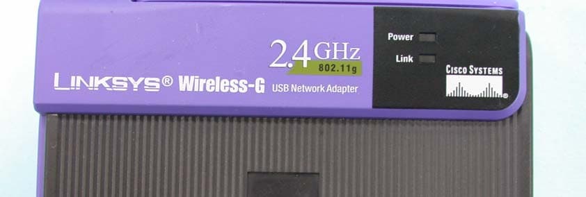
Click to zoom
Application Details
- Equipment Class
- DTS - Digital Transmission System
- Date of Grant
- Mar 29, 2004
- Application Purpose
- Original Equipment
- Date of Application
- Mar 29, 2004
- Equipment Note
- Wireless-G USB Network Adapter
- Frequency Range
- 2412.00000000 - 2462.00000000
- Company
- LINKSYS LLC
- Country
- United States
Documents & Files
Document Text
Text extracted from the exhibit documents filed with the FCC. Open a document above to read the original.
Users Manual
User Guide Wireless-G USBNetwork AdapterUse this Guide to install: WUSB54G COPYRIGHT & TRADEMARKS Specifications are subject to change without notice. Linksys is a registered trademark ortrademark of Cisco Systems, Inc. and/or its affiliates in the U.S. and certain other coun-tries. Copyright © 2003 Cisco Systems, Inc. All rights reserved. Other brands and prod-uct names are trademarks or registered trademarks of their respective holders.LIMITED WARRANTY Linksys guarantees that every Wireless-G USB Network Adapter will be free from physi-cal defects in material and workmanship for three years from the date of purchase, whenused within the limits set forth in the Specifications section of this User Guide. If the prod-uct proves defective during this warranty period, call Linksys Technical Support in orderto obtain a Return Authorization number. BE SURE TO HAVE YOUR PROOF OF PUR-CHASE ON HAND WHEN CALLING. When returning a product, mark the ReturnAuthorization number clearly on the outside of the package and include a copy of youroriginal proof of purchase. RETURN REQUESTS CANNOT BE PROCESSED WITHOUTPROOF OF PURCHASE. All customers located outside of the United States of Americaand Canada shall be held responsible for shipping and handling charges.IN NO EVENT SHALL LINKSYS'S LIABILITY EXCEED THE PRICE PAID FOR THE PROD-UCT FROM DIRECT, INDIRECT, SPECIAL, INCIDENTAL, OR CONSEQUENTIAL DAM-AGES RESULTING FROM THE USE OF THE PRODUCT, ITS ACCOMPANYING SOFT-WARE, OR ITS DOCUMENTATION. LINKSYS OFFERS NO REFUNDS FOR ITS PROD-UCTS. Linksys makes no warranty or representation, expressed, implied, or statutory,with respect to its products or the contents or use of this documentation and all accom-panying software, and specifically disclaims its quality, performance, merchantability, orfitness for any particular purpose. Linksys reserves the right to revise or update its prod-ucts, software, or documentation without obligation to notify any individual or entity.Please direct all inquiries to:Linksys P.O. Box 18558, Irvine, CA 92623. SAFETY AND REGULATORY NOTICESFCC STATEMENTThe Wireless-G USB Network Adapter has been tested and found to comply with thespecifications for a Class B digital device, pursuant to Part 15 of the FCC Rules.Operation is subject to the following two conditions: (1) This device may not cause harmful interference, and (2) This device must accept any interference received, including interference that may cause undesired operation. These limits are designed to provide reasonable protection against harmful interferencein a residential installation. This equipment generates, uses, and can radiate radio fre-quency energy and, if not installed and used according to the instructions, may causeharmful interference to radio communications. However, there is no guarantee that inter-ference will not occur in a particular installation. If this equipment does cause harmfulinterference to radio or television reception, which is found by turning the equipment offand on, the user is encouraged to try to correct the interference by one or more of thefollowing measures:• Reorient or relocate the receiving antenna • Increase the separation between the equipment or devices • Connect the equipment to an outlet other than the receiver's • Consult a dealer or an experienced radio/TV technician for assistance FCC Caution: Any change or modification to the product not expressly approved byLinksys could void the user's authority to operate the device.FCC RF Radiation Exposure StatementTo comply with the FCC and ANSI C95.1 RF exposure limits, the antenna(s) for thisdevice must comply with the following:• Access points with 2.4 GHz or 5 GHz integrated antenna must operate with a sepa-ration distance of at least 20 cm from all persons using the cable provided and mustnot be co-located or operating in conjunction with any other antenna or transmitter. End-users must be provided with specific operations for satisfying RF exposure compli-ance.Note: Dual antennas used for diversity operation are not considered co-located.Canadian Department of Communications Industry Canada (IC) NoticeThis Class B digital apparatus complies with Canadian ICES-003 and RSS-210.Cet appareil numérique de la classe B est conforme à la norme NMB-003 et CNR-210du Canada."To prevent radio interference to the licensed service, this device is intended to be oper-ated indoors and away from windows to provide maximum shielding. Equipment (or itstransmit antenna) that is installed outdoors is subject to licensing."" Pour empêcher que cet appareil cause du brouillage au service faisant l'objet d'unelicence, il doit être utilisé à l'intérieur et devrait être placé loin des fenêtres afin de fournirun écran de blindage maximal. Si le matériel (ou son antenne d'émission) est installé àl'extérieur, il doit faire l'objet d'une licence. "EC DECLARATION OF CONFORMITY (EUROPE)Linksys Group declares that the Instant Wireless ® Series products included in the Instant Wireless ® Series conform to the specifications listed below, following the provisions of the European R&TTE directive 1999/5/EC, EMC directive 89/336/EEC, and Low Voltagedirective 73/23/EEC: For 2.4 GHz devices with 100 mW radios, the following standards were applied: • ETS 300-826, 301 489-1 General EMC requirements for Radio equipment. • EN 609 50 Safety • ETS 300-328-2 Technical requirements for Radio equipment. Caution: This equipment is intended to be used in all EU and EFTA countries. Outdooruse may be restricted to certain frequencies and/or may require a license for operation.Contact local Authority for procedure to follow. Note: Combinations of power levels and antennas resulting in a radiated power level ofabove 100 mW equivalent isotropic radiated power (EIRP) are considered as not com-pliant with the above mentioned directive and are not allowed for use within the Europeancommunity and countries that have adopted the European R&TTE directive 1999/5/ECand/or the CEPT recommendat…
Text truncated - open the document above for the full version.
Users Manual
Chapter 6: Driver Installation forWindows XPAfter connecting the Adapter toyour PC, as shown in Chapter 5,you’ll need to install the driver.1. Windows XP will automati- cally detect the Adapter.Insert the Setup CD-ROMinto the CD-ROM drive.Click the radio button next toInstall the software auto-matically (Recommended)(as shown in Figure 6-1).Then click the Next button. 2. A screen similar to that shown in Figure 6-2 will appear, asking ifyou wish to discontinue installa-tion. This software has been test-ed and found to work properlywith Windows XP. Click theContinue Anyway button to continue installation. 3. The next screen shows that the Wizard is complete. Click theFinish button. The drivers are now installed. 11 10 4. When Windows 2000 begins installing the Network Adapter’s driver file, a screen similar to that shown in Figure 5-3 will appear, stating that a digitalsignature was not found. This software has been tested and found to workproperly with Windows 2000. Click the Ye s button to continue installation. If your PC is running Windows XP, proceed to “Chapter 6: Driver Installation for Windows XP.” If your PC is running Windows 2000, the installation of the Wireless-B USB Network Adapter is complete. If you want to check the link informa- tion, search for available wireless networks, or make additional configu- ration changes, proceed to “Chapter 7: Using the WLAN Monitor.” Figure 5-3 Figure 6-2 Figure 6-1 Figure 6-3 13 12 3. If WEP is enabled, the screen in Figure 6-6 willappear. Enter the WEP keyof your wireless network inthe Network key field, and re-enter it in the Confirm network key field. Then click the Connect button, and go to step 4. 4. The screen in Figure 6-7 will appear if your connection is active.For more information about wireless networking on a Windows XP computer,click Start and then Help and Support . Enter the keyword wireless in the field provided, and press the Enter key. Congratulations! The installation of the Wireless-G USB Network Adapter is complete. 1. After installing the Adapter, the Windows XP WirelessZero Configuration iconwill appear in your comput-er’s system tray (see Figure6-4). Double-click the icon. 2. The screen that appears will show any available wireless network. Select the network you want. If this network has WEPencryption enabled, go tostep 3.If this network does nothave WEP encryptionenabled, then Figure 6-5will appear. Make sure thebox next to Allow me to connect to the selectedwireless network, eventhough it is not secure is checked. Then click theConnect button, and go to step 4. Windows XP Wireless Zero Configuration Note for Windows XP users: Windows XP has a built-in configura- tion tool. Use Windows XP Wireless Zero Configuration (in the sys-tem tray at the bottom of your screen) to configure the Adapter. Figure 6-4 Figure 6-6 Note: Steps 2 and 3 are the instructions and screenshots for Windows XP with Service Pack 1 installed.If you have not installed Service Pack 1, select the network you want,and click the Connect button. If the network has WEP encryption enabled, enter the WEP key in the Network key field, and then click the Connect button. Note: Windows XP Wireless Zero Configuration does not support the use of a passphrase. Enter the exact WEP key used by your accesspoint. Figure 6-5 Figure 6-7 The Link Information screen, shown again in Figure 7-3, displays the signal strength and link quality information about the current connection and providesa button to click for additional status information. Ad-Hoc Mode or Infrastructure Mode - The screen indicates whether the Adapter is currently working in ad-hoc or infrastructure mode. Signal Strength - The Signal Strength bar indicates the signal strength. Link Quality - The Link Quality bar indicates the quality of the wireless net- work connection.Click the More Information button to view more information about the wire- less network connection, shown on the following page and in Figure 7-4..Click the X (Close) button in the upper right corner to exit the WLAN Monitor. 15 14 Link Information Figure 7-3 Chapter 7: Using the WLAN Monitor Use the WLAN Monitor to check the link information, search for availablewireless networks, or create profiles that hold different configuration settings.After installing the Adapter, the Wireless-G USB Network Adapter WLANMonitor icon will appear in your system tray. Double-click the icon (see Figure7-1).The Link Information screen will appear. (See Figure 7-2.) From this screen, you can find out how strong the current wirelesssignal is and how good the connection’s quality is. You can alsoclick the More Information button to view additional status information about the current wireless connection. To search foravailable wireless networks, click the Site Survey tab. To per- form configuration changes, click the Profiles tab. Figure 7-1 Figure 7-2 Accessing the WLAN MonitorOverview 17 16 The Site Survey screen, shown in Figure 7-5, displays a list of infrastructure and ad-hoc networks available for connection. SSID - The SSID or unique name of the wireless network. Signal - The percentage of signal strength, from 0 to 100%. Site InformationWireless Mode - The mode of the wireless network currently in use. Channel - The channel to which the wireless network devices are set. WEP - The status of the WEP encryption security feature. MAC - The MAC address of the wireless network’s access point. Surveyed at - The time at which the wireless network was scanned. Refresh - Click the Refresh button to perform a new search for wireless devices. Connect - To connect to one of the networks on the list, select the wireless net- work , and click the Connect button. If the wireless network has WEP encryp- tion enabled, you will see the screen shown in Figure 7-6. Figure 7-5 Site Survey Wireless Network StatusStatus - The status of the wireless network connection. SSID - The unique name of the wireless network. Wireless Mode - The mode of the wireless network cu…
Text truncated - open the document above for the full version.
Users Manual
Can I run an application from a remote computer over the wireless network?This will depend on whether or not the application is designed to be used over anetwork. Consult the application’s user guide to determine if it supports operationover a network.Can I play computer games with other members of the wireless network?Yes, as long as the game supports multiple players over a LAN (local area net-work). Refer to the game’s user guide for more information.What is the IEEE 802.11b standard?It is one of the IEEE standards for wireless networks. The 802.11b standard allowswireless networking hardware from different manufacturers to communicate, pro-vided that the hardware complies with the 802.11b standard. The 802.11b standardstates a maximum data transfer rate of 11Mbps and an operating frequency of2.4GHz.What IEEE 802.11b features are supported?The product supports the following IEEE 802.11b functions: • CSMA/CA plus Acknowledge protocol • Multi-Channel Roaming • Automatic Rate Selection • RTS/CTS feature • Fragmentation • Power Management What is ad-hoc mode?When a wireless network is set to ad-hoc mode, the wireless-equipped computersare configured to communicate directly with each other. The ad-hoc wireless net-work will not communicate with any wired network. What is infrastructure mode?When a wireless network is set to infrastructure mode, the wireless network isconfigured to communicate with a wired network through a wireless access point.What is roaming?Roaming is the ability of a portable computer user to communicate continuouslywhile moving freely throughout an area greater than that covered by a singleaccess point. Before using the roaming function, the workstation must make surethat it is the same channel number with the access point of dedicated coveragearea. 27 Appendix A: TroubleshootingThis chapter provides solutions to problems that may occur during the installa-tion and operation of the Wireless-G USB Network Adapter. Read the descrip-tions below to solve your problems. If you can’t find an answer here, check theLinksys website at www.linksys.com. 1. My computer does not recognize the USB Network Adapter.• Make sure that the USB Network Adapter is properly inserted into the USB port. • Also, make sure that the USB Controller is enabled in the BIOS. Check with your motherboard User Guide for more information. 2. The USB Network Adapter does not work properly.• Reinsert the USB Network Adapter into the notebook or desktop’s USB port. • Right-click on My Computer , and select Properties . Select the Adapter, then chose the Device Manager tab, and click on the Network Adapter. You will find the USB Network Adapter if it is installed successfully. If you seea yellow exclamation mark, the resources may be conflicting and you mustfollow the steps below:• Uninstall the driver software from your PC. • Restart your PC and repeat the hardware and software installation asspecified in this User Guide. 3. I cannot communicate with the other computers linked via Ethernet in the Infrastructure configuration. • Make sure that the notebook or desktop is powered on.• Make sure that your USB Network Adapter is configured on the same chan- nel, SSID, and WEP as the other computers in the Infrastructure configura-tion. 26 Frequently Asked Questions Common Problems and Solutions 29 28 Direct-Sequence Spread-Spectrum (DSSS) generates a redundant bit patternfor each bit to be transmitted. This bit pattern is called a chip (or chippingcode). The longer the chip, the greater the probability that the original data canbe recovered. Even if one or more bits in the chip are damaged during trans-mission, statistical techniques embedded in the radio can recover the originaldata without the need for retransmission. To an unintended receiver, DSSSappears as low power wideband noise and is rejected (ignored) by most nar-rowband receivers. Would the information be intercepted while transmitting on air?WLAN features two-fold protection in security. On the hardware side, as withDirect Sequence Spread Spectrum technology, it has the inherent security fea-ture of scrambling. On the software side, WLAN offers the encryption function(WEP) to enhance security and access control.What is WEP?WEP is Wired Equivalent Privacy, a data privacy mechanism based on a 64-bitor 128-bit shared key algorithm, as described in the IEEE 802.11 standard. To achieve true seamless connectivity, the wireless LAN must incorporate anumber of different functions. Each node and access point, for example, mustalways acknowledge receipt of each message. Each node must maintain contactwith the wireless network even when not actually transmitting data. Achievingthese functions simultaneously requires a dynamic RF networking technologythat links access points and nodes. In such a system, the user’s end node under-takes a search for the best possible access to the system. First, it evaluates suchfactors as signal strength and quality, as well as the message load currentlybeing carried by each access point and the distance of each access point to thewired backbone. Based on that information, the node next selects the rightaccess point and registers its address. Communications between end node andhost computer can then be transmitted up and down the backbone.As the user moves on, the end node’s RF transmitter regularly checks the sys-tem to determine whether it is in touch with the original access point or whetherit should seek a new one. When a node no longer receives acknowledgmentfrom its original access point, it undertakes a new search. Upon finding a newaccess point, it then re-registers, and the communication process continues.What is ISM band?The FCC and their counterparts outside of the U.S. have set aside bandwidthfor unlicensed use in the ISM (Industrial, Scientific and Medical) band.Spectrum in the vicinity of 2.4 GHz, in particular, is being made availableworldwide. This presents a truly revolutionary opportunity to place convenienthig…
Text truncated - open the document above for the full version.
External Photos
Page 1 CONSTRUCTION PHOTOS OF EUT Page 2 Page 3
Internal Photos
Page 1 CONSTRUCTION PHOTOS OF EUT Page 2 Page 3 Page 4 Page 5
Operational Description
FCC ID: Q87-WUSB54GV2 Report No.RF930305R03 Operational Description This device is a Wireless-G USB Adapter which operates in the 2.4GHz frequency spectrum with throughput of up to 54Mbps which OFDM technique will be applied. If the signal to noise radio is too poor which could not support 54Mbps, the 11Mbps data rate with CCK technique will be applied. The transmitter of the EUT is powered by host equipment via a USB interface. The antenna is Dipole antenna without connector. The other instruction, please have a look at the users manual.
RF Exposure Info
FCC ID: Q87-WUSB54GV2 Report No: SA930305R03 1 RF EXPOSURE REPORT REPORT NO.: SA930305R03 MODEL NO.: WUSB54Gv2 ACCORDING: FCC Guidelines for Human Exposure IEEE C95.1 APPLICANT: Cisco-Linksys, LLC ADDRESS: 121 Theory Drive, Irvine, CA 92612 (USA) ISSUED BY: Advance Data Technology Corporation LAB LOCATION: 47 14th Lin, Chiapau Tsun, Linko, Taipei, Taiwan, R.O.C. FCC ID: Q87-WUSB54GV2 Report No: SA930305R03 2 RF Exposure Measurement (Mobile Device) 1. Introduction In this document, we try to prove the safety of radiation harmfulness to the human body for our product. The limit for Maximum Permissible Exposure (MPE) specified in FCC 1.1310 is followed. The Gain of the antenna used in this product is measured in a Fully Anechoic Chamber (FAC) calibrated for antenna measurement in ADT, and also the maximum total power input to the antenna is measured. Through the Friis transmission formula and the maximum gain of the antenna, we can calculate the distance, away from the product, where the limit of MPE is reached. Although the Friis transmission formula is a far field assumption, the calculated result of that is an over-prediction for near field power density. We will take that as the worst case to specify the safety range. 2. RF Exposure Limit According to FCC 1.1310: The criteria listed in the following table shall be used to evaluate the environmental impact of human exposure to radio-frequency (RF) radiation as specified in 1.1307(b) LIMITS FOR MAXIMUM PERMISSIBLE EXPOSURE (MPE) Frequency Range (MHz) Electric Field Strength (V/m) Magnetic Field Strength (A/m) Power Density (mW/cm 2 ) Average Time (minutes) (A)Limits For Occupational / Control Exposures 300-1500......F/3006 1500-100,000......56 (B)Limits For General Population / Uncontrolled Exposure 300-1500......F/15006 1500-100,000......1.030 F = Frequency in MHz FCC ID: Q87-WUSB54GV2 Report No: SA930305R03 3 3. Friis Formula Friis transmission formula : Pd = (Pout*G) / (4*pi*r 2 ) where Pd = power density in mW/cm 2 Pout = output power to antenna in mW G = gain of antenna in linear scale Pi = 3.1416 R = distance between observation point and center of the radiator in cm If we know the maximum Gain of the antenna and the total power input to the antenna, through the calculation, we will know the MPE value at distance 20cm. Ref. : David K. Cheng, Field and Wave Electromagnetics, Second Edition, Page 640, Eq. (11-133). 4 EUT Operating condition The software provided by Manufacturer enabled the EUT to transmit and receive data at lowest, middle and highest channel individually. 5. Classification This device is not fixed inside the host equipment, it is connected with host through wire. So it is easy to be re-located in the place where at least 20cm far away from the body of the user. Warning statement to the user for keeping at least 20cm or more separation distance with the antenna should be included in users manual. So, this device is classified as Mobile Device. FCC ID: Q87-WUSB54GV2 Report No: SA930305R03 4 6 Test Results 6.1 Antenna Gain The maximum Gain measured in Fully Anechoic Chamber is 0dBi or 1(numeric). 6.2 Output Power Into Antenna & RF Exposure Distance : For Part 802.11b (CCK technique): Channel Channel Frequency (MHz) Output Power to Antenna (mW) Power Density (mW/cm 2 ) Limit of Power Density (mW/cm 2 ) 1241251.5230.0101.0 6243751.2860.0101.0 11246250.8160.0101.0 For Part 802.11g (OFDM technique): Channel Channel Frequency (MHz) Output Power to Antenna (mW) Power Density (mW/cm 2 ) Limit of Power Density (mW/cm 2 ) 1241241.3050.0081.0 6243742.6580.0081.0 11246241.1150.0081.0
Test Report
FCC ID: Q87-WUSB54GV2 Report No.: RF930305R031Issued: March 8, 2004 FCC TEST REPORT REPORT NO.: RF930305R03 MODEL NO.: WUSB54Gv2 RECEIVED: February 16, 2004 TESTED: February 16 ~ March 6, 2004 APPLICANT: Cisco-Linksys, LLC ADDRESS: 121 Theory Drive Irvine, CA 92612 (USA) ISSUED BY: Advance Data Technology Corporation LAB LOCATION: 47 14th Lin, Chiapau Tsun, Linko, Taipei, Taiwan, R.O.C. This test report consists of 68 pages in total. It may be duplicated completely for legal use with the approval of the applicant. It should not be reproduced except in full, without the written approval of our laboratory. The client should not use it to claim product endorsement by CNLA or any government agencies. The test results in the report only apply to the tested sample. 0528 ILAC MRA FCC ID: Q87-WUSB54GV2 Report No.: RF930305R032Issued: March 8, 2004 Table of Contents 1CERTIFICATION ........................................................................................... 4 2SUMMARY OF TEST RESULTS................................................................... 5 3GENERAL INFORMATION ........................................................................... 6 3.1GENERAL DESCRIPTION OF EUT.............................................................. 6 3.2DESCRIPTION OF TEST MODES................................................................ 7 3.3GENERAL DESCRIPTION OF APPLIED STANDARDS ............................... 7 3.4DESCRIPTION OF SUPPORT UNITS .......................................................... 8 3.5CONFIGURATION OF SYSTEM UNDER TEST........................................... 9 4TEST TYPES AND RESULTS..................................................................... 10 4.1CONDUCTED EMISSION MEASUREMENT .............................................. 10 4.1.1LIMITS OF CONDUCTED EMISSION MEASUREMENT............................ 10 4.1.2TEST INSTRUMENTS ................................................................................ 10 4.1.3TEST PROCEDURES..................................................................................11 4.1.4DEVIATION FROM TEST STANDARD ........................................................11 4.1.5TEST SETUP .............................................................................................. 12 4.1.6EUT OPERATING CONDITIONS................................................................ 12 4.1.7TEST RESULTS.......................................................................................... 13 4.2RADIATED EMISSION MEASUREMENT ................................................... 19 4.2.1LIMITS OF RADIATED EMISSION MEASUREMENT................................. 19 4.2.2TEST INSTRUMENTS ................................................................................ 20 4.2.3TEST PROCEDURES................................................................................. 21 4.2.4DEVIATION FROM TEST STANDARD ....................................................... 21 4.2.5TEST SETUP .............................................................................................. 22 4.2.6EUT OPERATING CONDITIONS................................................................ 22 4.2.7.TEST RESULTS.......................................................................................... 23 4.2.8.TEST RESULTS (FOR CCK)...................................................................... 25 4.2.9.TEST RESULTS (FOR OFDM) ................................................................... 28 4.36dB BANDWIDTH MEASUREMENT .......................................................... 31 4.3.1LIMITS OF 6dB BANDWIDTH MEASUREMENT ........................................ 31 4.3.2TEST INSTRUMENTS ................................................................................ 31 4.3.3TEST PROCEDURE ................................................................................... 32 4.3.4DEVIATION FROM TEST STANDARD ....................................................... 32 4.3.5TEST SETUP .............................................................................................. 32 4.3.6EUT OPERATING CONDITIONS................................................................ 32 FCC ID: Q87-WUSB54GV2 Report No.: RF930305R033Issued: March 8, 2004 4.3.7TEST RESULTS(FOR CCK) ....................................................................... 33 4.3.8TEST RESULTS(FOR OFDM) .................................................................... 37 4.4MAXIMUM PEAK OUTPUT POWER .......................................................... 41 4.4.1LIMITS OF MAXIMUM PEAK OUTPUT POWER MEASUREMENT ........... 41 4.4.2TEST INSTRUMENTS ................................................................................ 41 4.4.3TEST PROCEDURES................................................................................. 42 4.4.4DEVIATION FROM TEST STANDARD ....................................................... 42 4.4.5TEST SETUP .............................................................................................. 42 4.4.6EUT OPERATING CONDITIONS................................................................ 42 4.4.7TEST RESULTS(FOR CCK) ....................................................................... 43 4.4.8TEST RESULTS(FOR OFDM) .................................................................... 43 4.5POWER SPECTRAL DENSITY MEASUREMENT...................................... 44 4.5.1LIMITS OF POWER SPECTRAL DENSITY MEASUREMENT ................... 44 4.5.2TEST INSTRUMENTS ................................................................................ 44 4.5.3TEST PROCEDURE ................................................................................... 45 4.5.4DEVIATION FROM TEST STANDARD ....................................................... 45 4.5.5TEST SETUP .............................................................................................. 45 4.5.6EUT OPERATING CONDITIONS...............................................................…
Text truncated - open the document above for the full version.
Test Setup Photos
FCC ID: Q87-WUSB54GV2 Report No.: RF930305R0366Issued: March 8, 2004 5 PHOTOGRAPHS OF THE TEST CONFIGURATION CONDUCTED EMISSION TEST FCC ID: Q87-WUSB54GV2 Report No.: RF930305R0367Issued: March 8, 2004 RADIATED EMISSION TEST
Contact Information
Applicant
Po-Wen Cheng(Regulatory Compliance Manager)
Technical Contact
Advance Data Technology Corp.Ellis Wu
[email protected]+886-3-327-0910
13-1 Lane 19 WenShan 3rd Street · Taoyuan · Taiwan
Test Firm
Advance Data Technology CorporationStephen Chen
Technical Specifications
| # | Rule Parts | Frequency Range | Power Output |
|---|---|---|---|
| 1 | 15C | 2.41 GHz - 2.46 GHz | 52.00 mW |
Other Applications from LINKSYS LLC

Q87-WDS060
Aug 11, 2020WiFi Smart Light Switch with Dimmer
Equipment Class
DTS - Digital Transmission System
Q87-03564
Jun 28, 2020Linksys Tri-Band Wireless-AC Router
Equipment Class
NII - Unlicensed National Information Infrastructure TX
Q87-03566
Jun 23, 2020Linksys Tri-Band Wireless-AC Router
Equipment Class
NII - Unlicensed National Information Infrastructure TX
Q87-03530
Apr 29, 2020Linksys MAX-STREAM AC1900+ WiFi Range Extender
Equipment Class
NII - Unlicensed National Information Infrastructure TX
Q87-08151
Mar 30, 2020Linksys Dual-Band 802.11ax Wireless Router
Equipment Class
DTS - Digital Transmission System