Q87-WUSB6300Linksys Dual Band Wireless-AC USB Adapter
LINKSYS LLC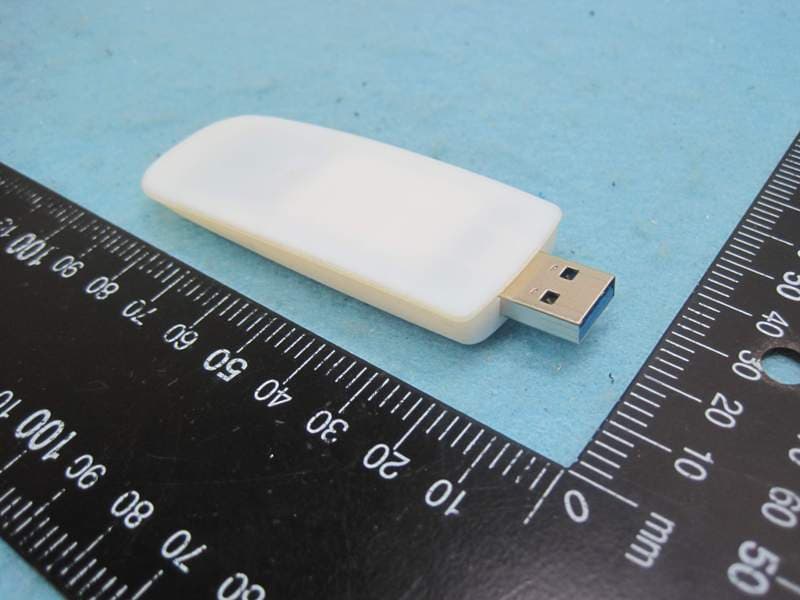
Click to zoom
Application Details
- Equipment Class
- DTS - Digital Transmission System
- Date of Grant
- Jun 18, 2013
- Application Purpose
- Original Equipment
- Date of Application
- Jun 18, 2013
- Equipment Note
- Linksys Dual Band Wireless-AC USB Adapter
- Frequency Range
- 5775.00000000 - 5775.00000000
- Company
- LINKSYS LLC
- Country
- United States
Documents & Files
Document Text
Text extracted from the exhibit documents filed with the FCC. Open a document above to read the original.
Users Manual
i Linksys WUSB6300 Contents Product Overview Features 1 Installation Installation 2 Wireless Network Configuration Wi-Fi Protected Setup 3 Wireless network configuration utility 3 Opera ting system’s built-in wireless network setup 3 Troubleshooting WUSB6300 10 Specifications Linksys WUSB6300 11 1 Product Overview Linksys WUSB6300 Thank you for choosing the Linksys dual-band wireless USB AC1200 adapter. Using the latest wireless networking technology, the adapter adds or upgrades wireless connectivity on your Windows-based desktop or laptop computer. To help protect your data and privacy, you can configure your home network and this adapter to use Wi-Fi Protected Access 2 (WPA2) encryption. Features Wi-Fi Protected Setup button USB plug WPS/Security LED Power/Status LED USB plug: Connect this end to any available USB port on your computer. Power/Status LED: Flashes when there is wireless network activity. Wi-Fi Protected Setup button: Press this button and the Wi-Fi Protected Setup button on your router or access point to connect your computer to the wireless network. WPS/Security LED: Indicates security status and provides feedback during Wi-Fi Protected Setup handshaking. Product Overview 2 Installation Linksys WUSB6300 This chapter describes the procedure for installing the adapter. Installation To install the adapter: 1. Insert the CD into your CD or DVD drive. 2. For Windows 8, click Tap to choose what happens to this disc in the upper-right corner of the screen. 3. Click Set up your Linksys Adapter. If you do not see a pop-up menu for the CD, access Setup on the CD directly. To access the CD, perform the following steps for your operating system: Windows 8 a. Type Computer at the main screen, then click Computer when it appears in the Apps list. b. Double -click your CD or DVD drive. Windows 7 and Windows Vista a. Click S tart, then click Computer. b. Double -click your CD or DVD drive. Windows XP a. Click Start, then click My Computer. b. Double -click your CD or DVD drive. 4. Follo w the on-screen instructions to finish setting up your Linksys wireless adapter. Note You need to run Setup only once to install your adapter. After you run Setup, your computer recognizes the adapter each time it is connected to your computer’s USB port. Installation 3 Wi-Fi Protected Setup Linksys WUSB6300 To configure the adapter’s wireless connection settings, you can use: •Wi-Fi Protected Setup™ (if your router, gateway, or access point supports it) •Your computer’s wireless network configuration utility •Your operating system’s built-in wireless network setup Wi-Fi Protected Setup To connect using Wi-Fi Protected Setup: 1. Press the Wi-Fi Protected Setup button on your wireless router, gateway, or access point. 2. Within two minutes, press and hold the Wi-Fi Protected Setup button on the side of your adapter for at least three seconds. The LED flashes while connecting, then stays solid when the connection is complete. Wi-Fi Protected Setup button Wireless network configuration utility If your computer has a wireless network configuration utility installed, refer to that utility’s documentation for instructions. Operating system’s built-in wireless network setup Follow the instructions in the appropriate section below to use your operating system’s built-in utility: •“Windows 8” on page 3 •”Windows 7” on page 4 •“Windows Vista” on page 5 •“Windows XP” on page 7 Windows 8 After you have installed the adapter, move your mouse pointer to the lower-right corner of the screen, then click Settings. Click the wireless network icon . The Network menu opens from the right side of the screen, showing you available wireless networks and your current connection status. Wireless Network Configuration 4 Operating system’s built-in wireless network setup Linksys WUSB6300 New Wireless Connection To connect to a different wireless network: 1. Mo ve your mouse pointer to the lower-right corner of the screen, then click Settings. 2. Click the wireless network icon . The Network menu opens, showing you available wireless networks and your current connection status. 3. If prompted, enter any additional required network information (such as password). Windows 7 After you have installed the adapter, the Wireless Network Configuration utility icon appears on your computer’s system tray. (If you do not see the icon, click the Show hidden icons arrow in the system tray.) When your mouse pointer hovers over the icon, the status information of your wireless connection appears. New Wireless Connection To connect to a different wireless network: 1. Click the W ireless Network Configuration utility icon. A list of available wireless networks appears. 2. Select your network, and then click Connect. If your network does not use wireless security, your computer now connects to the wireless network, and you are done. 5 Operating system’s built-in wireless network setup Linksys WUSB6300 3. Enter the Wi-Fi Protected Access (WPA/WPA2) passphrase or the Wired Equivalent Privacy (WEP) key (depending on your type of security), then click OK. This screen appears while the adapter connects to your network. Do not cancel, unless you want to end the connection. Your computer is now connected to your wireless network. Note For help with the Wireless Network Configuration utility, click Start, then click Help and Support. Windows Vista After you have installed the adapter, the Wireless Network Configuration utility icon appears on your computer’s system tray. When your mouse pointer hovers over the icon, the status information of your wireless connection appears. New Wireless Connection To connect to a different wireless network: 1. Right-click the Wireless Network Configuration utility icon. 2. Click Connect to a network. 6 Operating system’s built-in wireless network setup Linksys WUSB6300 3. Select your network, then click Connect. 4. If your network uses wireless security, go to Step 5. If your network does not use wireless security, this …
Text truncated - open the document above for the full version.
External Photos
Report No.: 2N0801-01 SPORTON International Inc. PAGE NUMBER : 1 OF 2 TEL : 886-2-2696-2468 ISSUED DATE : May 31, 2013 FAX : 886-2-2696-2255 Photographs of EUT Report No.: 2N0801-01 SPORTON International Inc. PAGE NUMBER : 2 OF 2 TEL : 886-2-2696-2468 ISSUED DATE : May 31, 2013 FAX : 886-2-2696-2255
Internal Photos
Report No.: 2N0801-01 SPORTON International Inc. PAGE NUMBER : 1 OF 5 TEL : 886-2-2696-2468 ISSUED DATE : May 31, 2013 FAX : 886-2-2696-2255 Photographs of EUT Report No.: 2N0801-01 SPORTON International Inc. PAGE NUMBER : 2 OF 5 TEL : 886-2-2696-2468 ISSUED DATE : May 31, 2013 FAX : 886-2-2696-2255 Report No.: 2N0801-01 SPORTON International Inc. PAGE NUMBER : 3 OF 5 TEL : 886-2-2696-2468 ISSUED DATE : May 31, 2013 FAX : 886-2-2696-2255 Report No.: 2N0801-01 SPORTON International Inc. PAGE NUMBER : 4 OF 5 TEL : 886-2-2696-2468 ISSUED DATE : May 31, 2013 FAX : 886-2-2696-2255 Report No.: 2N0801-01 SPORTON International Inc. PAGE NUMBER : 5 OF 5 TEL : 886-2-2696-2468 ISSUED DATE : May 31, 2013 FAX : 886-2-2696-2255
RF Exposure Info
SPORTON INTERNATIONAL INC. TEL : 886-3-327-3456 FAX : 886-3-328-4978 D2450V2, serial no. 736 Extended Dipole Calibrations Referring to KDB 450824, if dipoles are verified in return loss (<-20dB, within 20% of prior calibration), and in impedance (within 5 ohm of prior calibration), the annual calibration is not necessary and the calibration interval can be extended. <Justification Procedure of Extended Dipole Calibration> 1. Setup a Network Analyzer (Agilent N5230A) and set the start frequency and stop frequency to Network Analyzer according to the dipole frequency, at least +/- 200MHz around the calibration point. 2. Using calibration kit to perform Network Analyzer Open, Short and Load calibration. 3. Connect the dipole with the calibrated Network Analyzer. 4. Place the dipole underneath the phantom which is filled with head-simulating or body-simulating liquid. 5. Set the Network Analyzer frequency by the dipole calibration frequency. Monitor the return-loss and impedance results with Log Magnitude format and Smith Chart, respectively. 6. Record the result and compare with the prior calibration. Please check the Appendix C for detail records. <Justification of the extended calibration> D2450V2 – serial no. 736 2450 Head 2450 Body Date of Measurement Return-Loss (dB) Delta (%) Real Impedance (ohm) Delta (ohm) Imaginary Impedance (ohm) Delta (ohm) Return-Loss (dB) Delta (%) Real Impedance (ohm) Delta (ohm) Imaginary Impedance (ohm) Delta (ohm) 7.25.2011 -27.042 54.398 1.4805 -30.696 50.812 2.8262 7.25.2012 -27.950 -3.365 52.541 1.857 0.77343 0.707 -31.781 -3.535 50.572 0.24 1.5953 1.2309 The return loss is < -20dB, within 20% of prior calibration; the impedance is within 5 ohm of prior calibration. Therefore the verification result should support extended calibration. SPORTON INTERNATIONAL INC. TEL : 886-3-327-3456 FAX : 886-3-328-4978 <Dipole Verification Data> - D2450 V2, serial no. 736 (Date of Measurement : 7.25.2012) 2450 MHz - Head SPORTON INTERNATIONAL INC. TEL : 886-3-327-3456 FAX : 886-3-328-4978 2450 MHz – Body
RF Exposure Info
SPORTON INTERNATIONAL INC. Page Number : 1 of 41 TEL : 886-3-327-3456 Report Issued Date : May 31, 2013 FAX : 886-3-328-4978 Report Version : Rev. 01 FCC ID : Q87-WUSB6300 FCC SAR Test Report Report No. : FA2N0801-01 FCC SAR Test Report APPLICANT : Linksys LLC EQUIPMENT : Linksys Dual Band Wireless-AC USB Adapter BRAND NAME : Linksys MODEL NAME : WUSB6300 FCC ID : Q87-WUSB6300 STANDARD : FCC 47 CFR Part 2 (2.1093) ANSI/IEEE C95.1-1992 IEEE 1528-2003 FCC OET Bulletin 65 Supplement C (Edition 01-01) The product was completely tested on Dec. 06, 2012. We, SPORTON INTERNATIONAL INC., would like to declare that the tested sample has been evaluated in accordance with the procedures and shown the compliance with the applicable technical standards. The test results in this report apply exclusively to the tested model / sample. Without written approval of SPORTON INTERNATIONAL INC., the test report shall not be reproduced except in full. SPORTON INTERNATIONAL INC. No. 52, Hwa Ya 1 st Rd., Hwa Ya Technology Park, Kwei-Shan Hsiang, Tao Yuan Hsien, Taiwan, R.O.C. Approved by: Jones Tsai / Manager Reviewed by: Eric Huang / Deputy Manager SPORTON INTERNATIONAL INC. Page Number : 2 of 41 TEL : 886-3-327-3456 Report Issued Date : May 31, 2013 FAX : 886-3-328-4978 Report Version : Rev. 01 FCC ID : Q87-WUSB6300 FCC SAR Test Report Report No. : FA2N0801-01 Table of Contents 1. Statement of Compliance ............................................................................................................................................. 4 2. Administration Data ...................................................................................................................................................... 5 2.1 Testing Laboratory .................................................................................................................................................. 5 2.2 Applicant ................................................................................................................................................................ 5 2.3 Manufacturer .......................................................................................................................................................... 5 2.4 Application Details .................................................................................................................................................. 5 3. General Information ...................................................................................................................................................... 6 3.1 Description of Equipment Under Test (EUT) .......................................................................................................... 6 3.2 Maximum RF output power among production units .............................................................................................. 7 3.3 Applied Standards .................................................................................................................................................. 7 3.4 Device Category and SAR Limits ........................................................................................................................... 7 3.5 Test Conditions ....................................................................................................................................................... 7 4. Specific Absorption Rate (SAR) ................................................................................................................................... 8 4.1 Introduction ............................................................................................................................................................ 8 4.2 SAR Definition ........................................................................................................................................................ 8 5. SAR Measurement System ........................................................................................................................................... 9 5.1 E-Field Probe ........................................................................................................................................................10 5.2 Data Acquisition Electronics (DAE) ....................................................................................................................... 11 5.3 Robot .................................................................................................................................................................... 11 5.4 Measurement Server ............................................................................................................................................. 11 5.5 Phantom ................................................................................................................................................................12 5.6 Device Holder........................................................................................................................................................13 5.7 Data Storage and Evaluation ................................................................................................................................14 5.8 Test Equipment List ...............................................................................................................................................16 6. Tissue Simulating Liquids ...........................................................................................................................................17 7. SAR Measurement Evaluation ....................................................................................................................................19 7.1 Purpose of System Performance check ................................................................................................................19 7.2 System Setup .......................................…
Text truncated - open the document above for the full version.
RF Exposure Info
Test Laboratory: Sporton International Inc. SAR/HAC Testing Lab Date: 2012/12/6 #32_WLAN2.4G_802.11b_Horizontal Up_0.5cm_Ch11;Ant 2 DUT: 2N0801-01 Communication System: 802.11b; Frequency: 2462 MHz;Duty Cycle: 1:1 Medium: MSL_2450_121206 Medium parameters used: f = 2462 MHz; σ = 2.032 mho/m; ε r = 53.846; ρ = 1000 kg/m 3 Ambient Temperature:22.5 °C; Liquid Temperature:21.5 °C DASY5 Configuration: - Probe: EX3DV4 - SN3792; ConvF(7.1, 7.1, 7.1); Calibrated: 2012/6/21; - Sensor-Surface: 2mm (Mechanical Surface Detection) - Electronics: DAE4 Sn1338; Calibrated: 2012/6/12 - Phantom: ELI 4.0_Front; Type: QDOVA001BB; Serial: 1026 - Measurement SW: DASY52, Version 52.8 (3);SEMCAD X Version 14.6.5 (6469) Configuration/Ch11/Area Scan (51x101x1): Measurement grid: dx=12mm, dy=12mm Maximum value of SAR (interpolated) = 1.68 mW/g Configuration/Ch11/Zoom Scan (7x7x7)/Cube 0: Measurement grid: dx=5mm, dy=5mm, dz=5m m Reference Value = 28.156 V/m; Power Drift = 0.02 dB Peak SAR (extrapolated) = 2.169 mW/g SAR(1 g) = 1.03 mW/g; SAR(10 g) = 0.467 mW/g Maximum value of SAR (measured) = 1.58 mW/g 0 dB = 1.58 mW/g = 3.97 dB mW/g Test Laboratory: Sporton International Inc. SAR/HAC Testing Lab Date: 2012/12/6 #51_WLAN2.4G_802.11b_Horizontal Up_0.5cm_Ch11;Ant 2_Repeat DUT: 2N0801-01 Communication System: 802.11b; Frequency: 2462 MHz;Duty Cycle: 1:1 Medium: MSL_2450_121206 Medium parameters used: f = 2462 MHz; σ = 2.032 mho/m; ε r = 53.846; ρ = 1000 kg/m 3 Ambient Temperature:22.5 °C; Liquid Temperature:21.5 °C DASY5 Configuration: - Probe: EX3DV4 - SN3792; ConvF(7.1, 7.1, 7.1); Calibrated: 2012/6/21; - Sensor-Surface: 2mm (Mechanical Surface Detection) - Electronics: DAE4 Sn1338; Calibrated: 2012/6/12 - Phantom: ELI 4.0_Front; Type: QDOVA001BB; Serial: 1026 - Measurement SW: DASY52, Version 52.8 (3);SEMCAD X Version 14.6.5 (6469) Configuration/Ch11/Area Scan (51x101x1): Measurement grid: dx=12mm, dy=12mm Maximum value of SAR (interpolated) = 1.40 mW/g Configuration/Ch11/Zoom Scan (7x7x7)/Cube 0: Measurement grid: dx=5mm, dy=5mm, dz=5m m Reference Value = 26.131 V/m; Power Drift = 0.056 dB Peak SAR (extrapolated) = 2.204 mW/g SAR(1 g) = 1.02 mW/g; SAR(10 g) = 0.459 mW/g Maximum value of SAR (measured) = 1.60 mW/g 0 dB = 1.60 mW/g = 4.08 dB mW/g Test Laboratory: Sporton International Inc. SAR/HAC Testing Lab Date: 2012/12/6 #33_WLAN2.4G_802.11b_Horizontal Down_0.5cm_Ch11;Ant 2 DUT: 2N0801-01 Communication System: 802.11b; Frequency: 2462 MHz;Duty Cycle: 1:1 Medium: MSL_2450_121206 Medium parameters used: f = 2462 MHz; σ = 2.032 mho/m; ε r = 53.846; ρ = 1000 kg/m 3 Ambient Temperature:22.5 °C; Liquid Temperature:21.5 °C DASY5 Configuration: - Probe: EX3DV4 - SN3792; ConvF(7.1, 7.1, 7.1); Calibrated: 2012/6/21; - Sensor-Surface: 2mm (Mechanical Surface Detection) - Electronics: DAE4 Sn1338; Calibrated: 2012/6/12 - Phantom: ELI 4.0_Front; Type: QDOVA001BB; Serial: 1026 - Measurement SW: DASY52, Version 52.8 (3);SEMCAD X Version 14.6.5 (6469) Configuration/Ch11/Area Scan (51x101x1): Measurement grid: dx=12mm, dy=12mm Maximum value of SAR (interpolated) = 1.44 mW/g Configuration/Ch11/Zoom Scan (7x7x7)/Cube 0: Measurement grid: dx=5mm, dy=5mm, dz=5m m Reference Value = 27.494 V/m; Power Drift = -0.06 dB Peak SAR (extrapolated) = 2.039 mW/g SAR(1 g) = 0.979 mW/g; SAR(10 g) = 0.449 mW/g Maximum value of SAR (measured) = 1.49 mW/g 0 dB = 1.49 mW/g = 3.46 dB mW/g Test Laboratory: Sporton International Inc. SAR/HAC Testing Lab Date: 2012/12/6 #34_WLAN2.4G_802.11b_Vertical Front_0.5cm_Ch11;Ant 2 DUT: 2N0801-01 Communication System: 802.11b; Frequency: 2462 MHz;Duty Cycle: 1:1 Medium: MSL_2450_121206 Medium parameters used: f = 2462 MHz; σ = 2.032 mho/m; ε r = 53.846; ρ = 1000 kg/m 3 Ambient Temperature:22.5 °C; Liquid Temperature:21.5 °C DASY5 Configuration: - Probe: EX3DV4 - SN3792; ConvF(7.1, 7.1, 7.1); Calibrated: 2012/6/21; - Sensor-Surface: 2mm (Mechanical Surface Detection) - Electronics: DAE4 Sn1338; Calibrated: 2012/6/12 - Phantom: ELI 4.0_Front; Type: QDOVA001BB; Serial: 1026 - Measurement SW: DASY52, Version 52.8 (3);SEMCAD X Version 14.6.5 (6469) Configuration/Ch11/Area Scan (51x101x1): Measurement grid: dx=12mm, dy=12mm Maximum value of SAR (interpolated) = 0.232 mW/g Configuration/Ch11/Zoom Scan (7x7x7)/Cube 0: Measurement grid: dx=5mm, dy=5mm, dz=5m m Reference Value = 10.422 V/m; Power Drift = -0.10 dB Peak SAR (extrapolated) = 0.288 mW/g SAR(1 g) = 0.144 mW/g; SAR(10 g) = 0.069 mW/g Maximum value of SAR (measured) = 0.213 mW/g 0 dB = 0.213 mW/g = -13.43 dB mW/g Test Laboratory: Sporton International Inc. SAR/HAC Testing Lab Date: 2012/12/6 #35_WLAN2.4G_802.11b_Vertical Back_0.5cm_Ch11;Ant 2 DUT: 2N0801-01 Communication System: 802.11b; Frequency: 2462 MHz;Duty Cycle: 1:1 Medium: MSL_2450_121206 Medium parameters used: f = 2462 MHz; σ = 2.032 mho/m; ε r = 53.846; ρ = 1000 kg/m 3 Ambient Temperature:22.5 °C; Liquid Temperature:21.5 °C DASY5 Configuration: - Probe: EX3DV4 - SN3792; ConvF(7.1, 7.1, 7.1); Calibrated: 2012/6/21; - Sensor-Surface: 2mm (Mechanical Surface Detection) - Electronics: DAE4 Sn1338; Calibrated: 2012/6/12 - Phantom: ELI 4.0_Front; Type: QDOVA001BB; Serial: 1026 - Measurement SW: DASY52, Version 52.8 (3);SEMCAD X Version 14.6.5 (6469) Configuration/Ch11/Area Scan (51x101x1): Measurement grid: dx=12mm, dy=12mm Maximum value of SAR (interpolated) = 1.19 mW/g Configuration/Ch11/Zoom Scan (7x7x7)/Cube 0: Measurement grid: dx=5mm, dy=5mm, dz=5m m Reference Value = 24.034 V/m; Power Drift = -0.03 dB Peak SAR (extrapolated) = 1.572 mW/g SAR(1 g) = 0.756 mW/g; SAR(10 g) = 0.349 mW/g Maximum value of SAR (measured) = 1.14 mW/g 0 dB = 1.14 mW/g = 1.14 dB mW/g Test Laboratory: Sporton International Inc. SAR/HAC Testing Lab Date: 2012/12/6 #36_WLAN2.4G_802.11b_Tip Mode_0.5cm_Ch11;Ant 2 DUT: 2N0801-01 Communication System: 802.11b; Frequency: 2462 MHz;Duty Cycle: 1:1 Medium: MSL_2450_121206 Medium parameters used: f = 2462 MHz; σ = 2.032 mho/m; ε r = 53.846; ρ = 1000 kg/m 3 Ambient Temperature:22.5 °C; L…
Text truncated - open the document above for the full version.
RF Exposure Info
Test Laboratory: Sporton International Inc. SAR/HAC Testing Lab Date: 2012/12/6 System Check_Body_2450MHz_121206 DUT: D2450V2-SN:736 Communication System: CW; Frequency: 2450 MHz;Duty Cycle: 1:1 Medium: MSL_2450_121206 Medium parameters used: f = 2450 MHz; σ = 2.015 mho/m; ε r = 53.858; ρ = 1000 kg/m 3 Ambient Temperature:22.5 °C; Liquid Temperature:21.5 °C DASY5 Configuration: - Probe: EX3DV4 - SN3792; ConvF(7.1, 7.1, 7.1); Calibrated: 2012/6/21; - Sensor-Surface: 2mm (Mechanical Surface Detection) - Electronics: DAE4 Sn1338; Calibrated: 2012/6/12 - Phantom: ELI 4.0_Front; Type: QDOVA001BB; Serial: 1026 - Measurement SW: DASY52, Version 52.8 (3);SEMCAD X Version 14.6.5 (6469) Configuration/Pin=250mW/Area Scan (61x61x1): Measurement grid: dx=12mm, dy=12mm Maximum value of SAR (interpolated) = 21.4 mW/g Configuration/Pin=250mW/Zoom Scan (7x7x7)/Cube 0: Measurement grid: dx=5mm, dy=5mm, dz=5m m Reference Value = 98.368 V/m; Power Drift = -0.12 dB Peak SAR (extrapolated) = 27.047 mW/g SAR(1 g) = 12.4 mW/g; SAR(10 g) = 5.76 mW/g Maximum value of SAR (measured) = 19.1 mW/g 0 dB = 19.1 mW/g = 25.62 dB mW/g Test Laboratory: Sporton International Inc. SAR/HAC Testing Lab Date: 2012/12/5 System Check_Body_5200MHz_121205 DUT: D5GHzV2-SN:1006 Communication System: CW; Frequency: 5200 MHz;Duty Cycle: 1:1 Medium: MSL_5G_121205 Medium parameters used: f = 5200 MHz; σ = 5.336 mho/m; ε r = 47.488; ρ = 1000 kg/m 3 Ambient Temperature:22.7 °C; Liquid Temperature:21.7 °C DASY5 Configuration: - Probe: EX3DV4 - SN3792; ConvF(4.2, 4.2, 4.2); Calibrated: 2012/6/21; - Sensor-Surface: 1.4mm (Mechanical Surface Detection) - Electronics: DAE4 Sn1338; Calibrated: 2012/6/12 - Phantom: ELI 4.0_Front; Type: QDOVA001BB; Serial: 1026 - Measurement SW: DASY52, Version 52.8 (3);SEMCAD X Version 14.6.5 (6469) Configuration/Pin=100mW/Area Scan (71x71x1): Measurement grid: dx=10mm, dy=10mm Maximum value of SAR (interpolated) = 21.6 mW/g Configuration/Pin=100mW/Zoom Scan (7x7x7)/Cube 0: Measurement grid: dx=4mm, dy=4mm, dz=1.4m m Reference Value = 49.906 V/m; Power Drift = -0.139 dB Peak SAR (extrapolated) = 32.800 mW/g SAR(1 g) = 7.36 mW/g; SAR(10 g) = 2.03 mW/g Maximum value of SAR (measured) = 18.1 mW/g 0 dB = 18.1 mW/g = 25.15 dB mW/g Test Laboratory: Sporton International Inc. SAR/HAC Testing Lab Date: 2012/12/5 System Check_Body_5800MHz_121205 DUT: D5GHzV2-SN:1006 Communication System: CW; Frequency: 5800 MHz;Duty Cycle: 1:1 Medium: MSL_5G_121205 Medium parameters used: f = 5800 MHz; σ = 6.243 mho/m; ε r = 46.387; ρ = 1000 kg/m 3 Ambient Temperature:22.6 °C; Liquid Temperature:21.6 °C DASY5 Configuration: - Probe: EX3DV4 - SN3792; ConvF(3.89, 3.89, 3.89); Calibrated: 2012/6/21; - Sensor-Surface: 1.4mm (Mechanical Surface Detection) - Electronics: DAE4 Sn1338; Calibrated: 2012/6/12 - Phantom: ELI 4.0_Front; Type: QDOVA001BB; Serial: 1026 - Measurement SW: DASY52, Version 52.8 (3);SEMCAD X Version 14.6.5 (6469) Configuration/Pin=100mW/Area Scan (71x71x1): Measurement grid: dx=10mm, dy=10mm Maximum value of SAR (interpolated) = 16.9 mW/g Configuration/Pin=100mW/Zoom Scan (7x7x7)/Cube 0: Measurement grid: dx=4mm, dy=4mm, dz=1.4m m Reference Value = 38.946 V/m; Power Drift = 0.190 dB Peak SAR (extrapolated) = 38.126 mW/g SAR(1 g) = 7.32 mW/g; SAR(10 g) = 1.98 mW/g Maximum value of SAR (measured) = 19.3 mW/g 0 dB = 19.3 mW/g = 25.71 dB mW/g
Test Report
SPORTON International Inc. No. 52, Hwa Ya 1st Rd., Kwei-Shan Hsiang, TaoYuan Hsien, Taiwan, R.O.C. Ph: 886-3-327-3456 / FAX: 886-3-327-0973 / www.sporton.com.tw Report Format Version: 01 FCC RADIO TEST REPORT Applicant’s company Linksys LLC Applicant Address 131 Theory Drive, Irvine Ca., 92617 FCC ID Q87-WUSB6300 Manufacturer’s company Linksys LLC Manufacturer Address 131 Theory Drive, Irvine Ca., 92617 Product Name Linksys Dual Band Wireless-AC USB Adapter Brand Name Linksys Model Name WUSB6300 Test Rule Part(s) 47 CFR FCC Part 15 Subpart C § 15.247 Test Freq. Range 2400 ~ 2483.5MHz / 5725 ~ 5850MHz Received Date Nov. 01, 2012 Final Test Date May 29, 2013 Submission Type Original Equipment Statement Test result included is only for the IEEE 802.11n, IEEE 802.11b/g part and IEEE 802.11a/ac (5725 ~ 5850MHz) of the product. The test result in this report refers exclusively to the presented test model / sample. Without written approval of SPORTON International Inc., the test report shall not be reproduced except in full. The measurements and test results shown in this test report were made in accordance with the procedures and found in compliance with the limit given in ANSI C63.10-2009, 47 CFR FCC Part 15 Subpart C, KDB 558074 D01 v03 and KDB 662911 D01 v01r02. The test equipment used to perform the test is calibrated and traceable to NML/ROC. Report No.: FR2N0801-01AB Report Format Version: 01 Page No. : i of ii FCC ID: Q87-WUSB6300 Issued Date :May 31, 2013 Table of Contents 1. CERTIFICATE OF COMPLIANCE ........................................................................................................................... 1 2. SUMMARY OF THE TEST RESULT ............................................................................................................................ 2 3. GENERAL INFORMATION..................................................................................................................................... 3 3.1. Product Details ........................................................................................................................................................................................... 3 3.2. Accessories ................................................................................................................................................................................................. 6 3.3. Table for Filed Antenna ............................................................................................................................................................................. 7 3.4. Table for Carrier Frequencies ................................................................................................................................................................... 8 3.5. Table for Test Modes .................................................................................................................................................................................. 9 3.6. Table for Testing Locations...................................................................................................................................................................... 11 3.7. Table for Supporting Units ....................................................................................................................................................................... 11 3.8. Table for Parameters of Test Software Setting ..................................................................................................................................... 11 3.9. Test Configurations................................................................................................................................................................................... 13 4. TEST RESULT......................................................................................................................................................... 15 4.1. AC Power Line Conducted Emissions Measurement ......................................................................................................................... 15 4.2. Maximum Conducted Output Power Measurement......................................................................................................................... 19 4.3. Power Spectral Density Measurement.................................................................................................................................................. 22 4.4. 6dB Spectrum Bandwidth Measurement ............................................................................................................................................. 31 4.5. Radiated Emissions Measurement......................................................................................................................................................... 41 4.6. Band Edge Emissions Measurement...................................................................................................................................................... 73 4.7. Antenna Requirements ........................................................................................................................................................................... 93 5. LIST OF MEASURING EQUIPMENTS .................................................................................................................... 94 6. TEST LOCATION..........................................................................................................…
Text truncated - open the document above for the full version.
Contact Information
Applicant
Po-Wen Cheng(Regulatory Compliance Manager)
Test Firm
Sporton International IncAlex Chen
Technical Specifications
| # | Rule Parts | Frequency Range | Power Output |
|---|---|---|---|
| 5 | 15C | 5.78 GHz - 5.78 GHz | 134.60 mW |
Other Applications from LINKSYS LLC

Q87-WDS060
Aug 11, 2020WiFi Smart Light Switch with Dimmer
Equipment Class
DTS - Digital Transmission System
Q87-03564
Jun 28, 2020Linksys Tri-Band Wireless-AC Router
Equipment Class
NII - Unlicensed National Information Infrastructure TX
Q87-03566
Jun 23, 2020Linksys Tri-Band Wireless-AC Router
Equipment Class
NII - Unlicensed National Information Infrastructure TX
Q87-03530
Apr 29, 2020Linksys MAX-STREAM AC1900+ WiFi Range Extender
Equipment Class
NII - Unlicensed National Information Infrastructure TX
Q87-08151
Mar 30, 2020Linksys Dual-Band 802.11ax Wireless Router
Equipment Class
DTS - Digital Transmission System