Q87-WVC54GWireless G Video Camera
LINKSYS LLC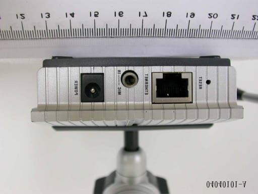
Click to zoom
Application Details
- Equipment Class
- DTS - Digital Transmission System
- Date of Grant
- May 27, 2004
- Application Purpose
- Original Equipment
- Date of Application
- May 27, 2004
- Equipment Note
- Wireless G Video Camera
- Frequency Range
- 2412.00000000 - 2462.00000000
- Company
- LINKSYS LLC
- Country
- United States
Documents & Files
Document Text
Text extracted from the exhibit documents filed with the FCC. Open a document above to read the original.
Users Manual
A Division of Cisco Systems, Inc. ® Model No. Internet Video Camera Wireless-G WVC54G User Guide WIRELESS GHz 2.4 802.11g Wireless-G Internet Video Camera Copyright and Trademarks Specifications are subject to change without notice. Linksys is a registered trademark or trademark of Cisco Systems, Inc. and/or its affiliates in the U.S. and certain other countries. Copyright © 2004 Cisco Systems, Inc. All rights reserved. Other brands and product names are trademarks or registered trademarks of their respective holders. How to Use this Guide Your guide to the Wireless-G Internet Video Camera has been designed to make understanding networking with the Camera easier than ever. Look for the following items when reading this guide: In addition to these symbols, there are definitions for technical terms that are presented like this: Also, each figure (diagram, screenshot, or other image) is provided with a figure number and description, like this: Figure numbers and descriptions can also be found in the “List of Figures” section in the “Table of Contents”. This exclamation point means there is a Caution or warning and is something that could damage your property or the Camera. word: definition. This checkmark means there is a Note of interest and is something you should pay special attention to while using the Camera. This question mark provides you with a reminder about something you might need to do while using the Camera. Figure 0-1: Sample Figure Description WVC54G-UG-40420NC JL Wireless-G Internet Video Camera Table of Contents Chapter 1: Introduction1 Welcome1 What’s in this Guide?2 Chapter 2: Planning Your Wireless Network4 Introduction4 Ad-Hoc and Infrastructure Modes4 Network Layout4 Chapter 3: Getting to Know the Wireless-G Internet Video Camera6 Camera LCD Screen and Built-in Microphone6 Camera LEDs6 Camera Head6 Camera Ports7 Chapter 4: Connecting the Wireless-G Internet Video Camera for Setup8 Overview8 Connection to a Wired Network for Setup8 Connection to a Wireless Ad-Hoc Network for Setup8 Moving the Camera to a Different Network9 Chapter 5: Setting up and Mounting the Wireless-G Internet Video Camera10 Setup Wizard10 Placement Options16 Audio Option16 Chapter 6: Installing and Using the Wireless-G Internet Video Camera Viewer & Recorder Utility17 Overview17 Installing the Viewer & Recorder Utility17 Using the Viewer & Recorder Utility19 Chapter 7: Setting up the Linksys SoloLink™ DDNS Service30 Overview30 Introduction30 Setup Wizard for the SoloLink DDNS Service30 SoloLink Registration of Additional Cameras40 Wireless-G Internet Video Camera Chapter 8: Using the Wireless-G Internet Video Camera’s Web-based Utility42 Overview42 How to Access the Web-based Utility42 View Video42 Setup43 Help54 Appendix A: Troubleshooting56 Common Problems and Solutions56 Frequently Asked Questions59 Appendix B: Wireless Security62 Security Precautions62 Security Threats Facing Wireless Networks62 Appendix C: Upgrading Firmware64 Appendix D: Windows Help65 Appendix E: Glossary66 Appendix F: Specifications73 Appendix G: Warranty Information75 Appendix H: Regulatory Information76 Appendix I: Contact Information79 Wireless-G Internet Video Camera List of Figures Figure 3-1: Camera LCD Screen and Built-in Microphone6 Figure 3-2: Camera LEDs6 Figure 3-3: Camera Head6 Figure 3-4: Camera Ports7 Figure 4-1: Connect the Ethernet Network Cable8 Figure 4-2: Connect the Power Adapter8 Figure 5-1: Setup Wizard - Welcome Screen10 Figure 5-2: Connection for Setup Screen10 Figure 5-3: Cameras Found Screen11 Figure 5-4: Login Screen11 Figure 5-5: Basic Settings Screen11 Figure 5-6: Network Settings Screen12 Figure 5-7: IP Settings Screen12 Figure 5-8: Mode Settings Screen13 Figure 5-9: Wireless Settings Screen13 Figure 5-10: Security Settings Screen14 Figure 5-11: Review New Settings Screen14 Figure 5-12: Confirmation Screen15 Figure 5-13: Congratulations Screen15 Figure 5-14: Stand Option16 Figure 5-15: Camera Desktop Stand16 Figure 5-16: Wall Mount Option16 Figure 5-17: Wall-Mount Slots16 Figure 6-1: Install Viewer & Recorder Utility Screen17 Figure 6-2: Install Viewer & Recorder Utility - Welcome Screen17 Figure 6-3: Choose Destination Location Screen18 Figure 6-4: Select Program Folder Screen18 Figure 6-5: OCX Plug-in Screen18 Wireless-G Internet Video Camera Figure 6-6: Setup Complete Screen18 Figure 6-7: Viewer & Recorder Utility Icon19 Figure 6-8: Main Screen19 Figure 6-9: Find Camera from LAN Screen20 Figure 6-10: Camera Added Successfully Screen20 Figure 6-11: Find Camera from Internet Screen21 Figure 6-12: Change Settings Screen21 Figure 6-13: Delete Camera Screen22 Figure 6-14: Confirm Deletion of Camera Screen22 Figure 6-15: View Video Screen23 Figure 6-16: Recording Icon Screen23 Figure 6-17: Scheduled Recordings in Progress Screen26 Figure 6-18: Files Screen26 Figure 6-19: Recorded Files Screen26 Figure 6-20: Window Showing SnapShot Folders27 Figure 6-21: Preferences Screen27 Figure 6-22: Recording Schedule Screen28 Figure 6-23: Add to Recording Schedule Screen28 Figure 6-24: Stop Scheduled Recording Screen29 Figure 6-25: View Video Screen29 Figure 7-1: SoloLink Service30 Figure 7-2: SoloLink Welcome Screen30 Figure 7-3: SoloLink for Dynamic IP Address Screen31 Figure 7-4: SoloLink for Convenience Screen31 Figure 7-5: Check Connections Screen32 Figure 7-6: Cameras Found Screen32 Figure 7-7: Login Screen33 Figure 7-8: SoloLink DDNS Screen33 Figure 7-9: Confirm Active Internet Connection Screen34 Figure 7-10: Welcome to the SoloLink DDNS Service Screen34 Wireless-G Internet Video Camera Figure 7-11: Sign Up Screen35 Figure 7-12: Confirmation of New Settings Screen36 Figure 7-13: Select a Location ID Screen36 Figure 7-14: Confirm Your Location ID Screen37 Figure 7-15: Payment Screen37 Figure 7-16: Verification Screen37 Figure 7-17: Create Links Screen38 Figure 7-18: Successful Registration Screen38 Figure 7-19: Account Confirmation of Camera Screen39 Figure 7-20: Successful Setup Screen39 Figure 7-21: …
Text truncated - open the document above for the full version.
Users Manual
13 Chapter 5: Setting up and Mounting the Wireless-G Internet Video Camera Setup Wizard Wireless-G Internet Video Camera 9. The Mode Setting screen will appear. Click the Infrastructure radio button if you want the Camera to communicate using an access point or wireless router. Click the Ad-Hoc radio button if you want the Camera to communicate without using an access point or wireless router. Click the Next button. 10. The Wireless Settings screen will appear, so you can change the wireless settings. Enter your wireless network’s SSID or network name. If you chose Ad-Hoc mode, select the channel at which the network broadcasts its wireless signal. •SSID. The SSID must be identical for all devices in a wireless network. It is case-sensitive and should have 32 alphanumeric characters or fewer. (You can use any keyboard character, but do not use any spaces.) •Channel. If you set the Camera to Ad-Hoc mode, select the appropriate channel from the drop-down menu. All devices in your wireless ad-hoc network must use the same channel in order to function correctly. Then click the Next button. Figure 5-8: Mode Settings Screen Figure 5-9: Wireless Settings Screen 14 Chapter 5: Setting up and Mounting the Wireless-G Internet Video Camera Setup Wizard Wireless-G Internet Video Camera 11. The Security Settings screen will appear. If your network has WEP encryption enabled, then select the level of WEP encryption and enter a Passphrase. If you want to manually enter a WEP key, leave the Passphrase field blank, and enter the WEP key in the Key 1 field. If your network doesn’t have WEP encryption disabled, keep the default, Disabled. •WEP. To enable WEP encryption, select 64-Bit Keys or 128-Bit Keys from the drop-down menu. Then enter a Passphrase. If you want to manually enter a WEP key, leave the Passphrase field blank. •Passphrase. If you enabled WEP encryption, you can enter a Passphrase, so a WEP key will be automatically generated. If you want to manually enter a WEP key, leave the Passphrase field blank. The Passphrase is case-sensitive and should have 16 alphanumeric characters or fewer. It must match the passphrase of your wireless network and is compatible with Linksys wireless products only. (You will have to enter the WEP key(s) manually on any non-Linksys wireless products.) •Key 1. If you want to manually enter a WEP key, complete this field. If you are using 64-bit WEP encryption, then the key must consist of exactly 10 hexadecimal characters. If you are using 128-bit WEP encryption, then the key must consist of 26 hexadecimal characters. Valid hexadecimal characters are “0” through “9” and “A” through “F”. Click the Next button. 12. Review your settings before the Setup Wizard starts to copy your files. Click the Next button to continue. Figure 5-10: Security Settings Screen Figure 5-11: Review New Settings Screen 15 Chapter 5: Setting up and Mounting the Wireless-G Internet Video Camera Setup Wizard Wireless-G Internet Video Camera 13. If you want to save the new settings, click the OK button. If you want to cancel your changes, click the Cancel button. 14. After the files have been successfully copied, the Congratulations screen will appear. •Install Viewer & Recorder Utility. Click this button to install the Camera’s Utility on your PC. •Setup SoloLink DDNS Service. Click the Setup SoloLink DDNS Service button to set up and configure the Linksys Dynamic Domain Name System (DDNS) service. •Exit. Click the Exit button if you want to install the Camera’s Utility later. Go to the “Placement Options” section. Figure 5-13: Congratulations Screen Figure 5-12: Confirmation Screen 16 Chapter 5: Setting up and Mounting the Wireless-G Internet Video Camera Placement Options Wireless-G Internet Video Camera Placement Options There are three ways to place the Camera. The first way is to place the Camera horizontally on a surface, so it sits on four small rubber feet. The second way is to stand the Camera vertically on a surface (see Figure 5-14). The third way is to hang the Camera on a wall (see Figure 5-16). The second and third options are explained in further detail below. Stand Option 1. The Camera includes a Camera Desktop Stand. Insert the bottom end into the Stand. 2. Place the Camera, and adjust its aim and focus accordingly. Wall Mount Option The Camera has two wall-mount slots on its back panel. The distance between the slots is 80 mm (3.15 inches). 1. Determine where you want to mount the Camera. Attach two screws to the wall, so that the Switch’s wall- mount slots line up with the two screws. 2. Maneuver the Camera so the screws are inserted into the two slots. 3. Adjust the Camera’s aim and focus accordingly. Proceed to the next section, “Audio Option.” Audio Option If you want to use your own microphone instead of the Camera’s built-in microphone, then follow these instructions: 1. Connect the 2.5 mm input jack of your microphone to the Camera’s MIC IN port on its bottom panel. The built- in microphone will automatically be disabled. 2. Place the external microphone in an appropriate location. The installation of the Wireless-G Internet Video Camera is complete. Go to “Chapter 6: Installing the Wireless-G Internet Video Camera Viewer & Recorder Utility.” If advanced users wish to access the Camera through its Web-based Utility, then proceed to “Chapter 8: Using the Wireless-G Internet Video Camera Web-based Utility.” Figure 5-16: Wall Mount Option Figure 5-14: Stand Option Figure 5-17: Wall-Mount Slots Figure 5-15: Camera Desktop Stand 17 Chapter 6: Installing and Using the Wireless-G Internet Video Camera Viewer & Recorder Utility Overview Wireless-G Internet Video Camera Chapter 6: Installing and Using the Wireless-G Internet Video Camera Viewer & Recorder Utility Overview This chapter will instruct you on how to install and use the Wireless-G Internet Video Camera Viewer & Recorder Utility on your PC. The Utility allows you to easily view and record the Camera’s video. If the Wi…
Text truncated - open the document above for the full version.
Users Manual
38 Chapter 7: Setting up the Linksys SoloLink™ DDNS Service Setup Wizard for the SoloLink DDNS Service Wireless-G Internet Video Camera 16. On the Create Links screen, click Continue. The SoloLink DDNS Service will send your account information to the Camera. 17. A pop-up screen, as shown in Figure 7-18, will inform you that you have successfully registered your account. Click OK. At the bottom of the SoloLink DDNS screen, click the Apply button to register the Camera with your account. Figure 7-17: Create Links Screen Figure 7-18: Successful Registration Screen 39 Chapter 7: Setting up the Linksys SoloLink™ DDNS Service Setup Wizard for the SoloLink DDNS Service Wireless-G Internet Video Camera 18. A confirmation page will display the link or address you will use to access the Camera and the port number the SoloLink DDNS Service will use to find the Camera (see Figure 7-19). Click Continue. 19. A pop-up screen, as shown in Figure 7-20, will inform you that you have successfully set up the SoloLink DDNS Service for the Camera. Click OK. Figure 7-19: Account Confirmation of Camera Screen Figure 7-20: Successful Setup Screen NOTE:Make sure you set up the port forwarding feature on your network router, so the SoloLink DDNS Service will be able to access the Camera. 40 Chapter 7: Setting up the Linksys SoloLink™ DDNS Service SoloLink Registration of Additional Cameras Wireless-G Internet Video Camera 20. Set up port forwarding on your network router, so the SoloLink DDNS Service will be able to track the Wireless-G Internet Video Camera. Go to www.linksys.com/portfwd for instructions on how to configure a Linksys router. For other routers, refer to your router’s documentation. The SoloLink DDNS setup is complete. If you want to register more Cameras with your SoloLink account, proceed to the “SoloLink Registration of Additional Cameras” section. For more information about the Camera’s Web-based Utility, proceed to “Chapter 8: Using the Wireless-G Internet Video Camera Web-based Utility.” SoloLink Registration of Additional Cameras After you have set up your SoloLink account, you can add more Cameras to your SoloLink account using each Camera’s Web-based Utility. Follow these instructions for each Camera you add: 1. To access a Camera’s Web-based Utility, launch Internet Explorer, and enter the Camera’s IP address in the Address field. (The default IP address is 192.168.1.115.) Then press Enter. 2. The Welcome screen will appear. Click the Setup tab. 3. A login screen will appear. (Windows XP users will see a similar screen.) Enter admin (the default user name and password) in the User Name and Password fields. Then click the OK button. 4. Click the SoloLink DDNS tab. Figure 7-21: Port Forwarding Information Figure 7-22: Web-based Utility Welcome Figure 7-23: Web Utility Login Screen 41 Chapter 7: Setting up the Linksys SoloLink™ DDNS Service SoloLink Registration of Additional Cameras Wireless-G Internet Video Camera 5. In the Username, Password, and Your Domain fields, enter your SoloLink account information (see Figure 7- 24). 6. In the Device Name field, give the Camera a unique name. The DDNS service will not work if multiple Cameras have the same Device Name. 7. In the WAN Port field, enter a unique port number. This is the number of the port you will use to access the Camera remotely. If you need to find an available port, click Find Available Port and follow the on-screen instructions (see Figure 7-25). The DDNS service will not work if multiple Cameras use the same WAN port. 8. Depending on how often you want the DDNS service to update the dynamic IP address, select the appropriate time interval from the DDNS Service Update drop-down menu. To update the dynamic IP address immediately, click the Update Now button. 9. Click the Apply button on the SoloLink DDNS screen. The Camera will automatically register itself with your SoloLink account. 10. Set up port forwarding on your network router, so the SoloLink DDNS Service will be able to track the Wireless-G Internet Video Camera. Go to www.linksys.com/portfwd for instructions on how to configure a Linksys router. For other routers, refer to your router’s documentation. The Camera has been added to your SoloLink account. For more information about the Camera’s Web-based Utility, proceed to “Chapter 8: Using the Wireless-G Internet Video Camera Web-based Utility.” Figure 7-24: SoloLink DDNS Screen Figure 7-25: Find Available Port Screen 42 Chapter 8: Using the Wireless-G Internet Video Camera’s Web-based Utility Overview Wireless-G Internet Video Camera Chapter 8: Using the Wireless-G Internet Video Camera’s Web-based Utility Overview Use the Camera’s Web-based Utility to access and alter its settings. This chapter will describe each webpage in the Utility and its features. The Utility can be accessed via the web browser of a computer connected to the Camera. How to Access the Web-based Utility To access the Utility, launch Internet Explorer, and enter the Camera’s IP address in the Address field. (The default IP address is 192.168.1.115.) Then press Enter. The Welcome screen of the Web-based Utility will appear. You have six tabs available: •Home. To return to the Welcome screen, click the Home tab. •View Video. To view the Camera’s video, click the View Video tab. Go to the “View Video” section for more information. •Setup. To alter the Camera’s settings, click the Setup tab. Go to the “Setup” section for more information. •Linksys WEB. To go to the Linksys website, www.linksys.com, click the Linksys WEB tab. •Help. The Help screen allows you to get information about the various Setup screens, download the latest Viewer & Recording Utility, download this User Guide, download Acrobat Reader, restore factory defaults, and upgrade the Camera’s firmware. Go to the “Help” section for more information. •Exit. To close the Utility, click the Exit tab. View Video Follow these instructions to view the Camera’s video. Figure 8-2: Web-based Utilit…
Text truncated - open the document above for the full version.
Cover Letter(s)
Apr 19, 2004 Federal Communications Commission Authorization and Evaluation Division FCC IDQ87-WVC54G Confidentiality Request Pursuant to Sections 0.457 and 0.459 of the Commission’s Rules, the Applicant Hereby requests confidential treatment of information accompaniment this Application As outlined below: 1. Block Diagram, 2. Schematic Diagram, The above materials contain trade secrets and proprietary information not customarily released to the public. The public disclosure of these matters might be harmful to the Applicant and provide unjustified benefits to its competitors. The Applicant understands that pursuant to Rule 0.457, disclosure of this Application and all accompanying documentation will not be made before the date of the Grant for this application Sincerely, ____________________________ Jennifer Yu / Associate Engineer Cisco-Linksys, LLC Tel: +1-949-823-3188 Fax: +1-949-823-3002 E-Mail: [email protected]
Cover Letter(s)
Federal Communications Commission Dear Sir, We, the undersigned, hereby authorize Exclusive Certification Corp. to act on our behalf in all matters relating to application for Wireless G Video Camera (Model: WVC54G, FCC ID No.: Q87-WVC54G)” authorization, including the signing of all documents relating to these matters. Any and all carried out by Exclusive Certification Corp. on our behalf shall have the same effect as acts of our own. The applicant certifies that in the case of an individual applicant (e.g., corporation), no party to the applicant is subject to a denial of federal benefits, that includes FCC benefits, pursuant to section 5301 of the Anti-drug abuse Act of 1988.21 U.S.A. 862. For a definition of a “party” for these purposes See 47 C.F.R. 1.2002(b). By: By: Jennifer Yu (Signature) (Printed) Title : Associate Engineer Applicant: Cisco-Linksys, LLC Address: 121 Theory Drive, Irvine, CA 92612, U.S.A Tel: +1-949-823-3188 Fax: +1-949-823-3002 E-mail: [email protected] Date: Apr 19, 2004
Cover Letter(s)
American Telecommunications Certification Body Inc. 6731 Whittier Ave, McLean, VA 22101 May 13, 2004 RE: Cisco/Lynksys FCC ID: Q87WVC54G I have a few comments on this Application. Depending on your responses, kindly understand there may be additional comments. 1.) The FCC ID on Form 731 does not match the label. Please be sure that there is an exact match on the FCC ID for all submitted documents for this filing. 2.) The Manual appears to lack the “Information to the User” language as required by 15.21. If this does indeed exist, my apologies. Please show me where I may find this statement. 3.) During radiated testing, was this equipment rotated about three orthogonal planes? 4.) Your RF Exposure exhibit shows both calculations for distance “R” and field density “S”. This is not permitted – the FCC only wants to see calculations for “S” at 20cm. The idea is that they do not want to encourage users to use this product at distances closer than 20cm. 5.) FYI: Your Internal Photographs are marginal. In the future, please limit your photographs to one per page, and make them sharp enough and clear enough to easily view details on the circuit board. William H. Graff President and Director of Engineering mailto: [email protected] The items indicated above must be submitted before processing can continue on the above referenced application. Failure to provide the requested information may result in application termination. Correspondence should be considered part of the permanent submission and may be viewed from the Internet after a Grant of Equipment Authorization is issued. Please do not respond to this correspondence using the email reply button. In order for your response to be processed expeditiously, you must submit your documents through the AmericanTCB.com website. Also, please note that partial responses increase processing time and should not be submitted. Any questions about the content of this correspondence should be directed to the sender.
ID Label/Location Info
Linksys(WVC54G) 57.30 mm 3 7 . 8 0 m m FCC ID: Q87-WVC54G WVC54G 57.30 mm 3 7 . 8 0 m m Contains an approved RF Module FCC ID: Q87-WVC54G This Class (B) digital apparatus complies with Canadian ICES-003,RSS210.IC ID: 3839A-WVC54G WVC54G
Operational Description
WVC54G SPECIFICATIONS 1. INTRODUCTION The Wireless Network Camera is a device which is able to provide video streaming images through Local-Area-Network and Internet. It supports both Ethernet or 802.11g WLAN. With a CMOS type digital image sensor and advanced MPEG-4 technology, it is able to display high quality video over Wireless LAN, LAN, and Internet. 2. BLOCK DIAGRAM TI CPU DM270 Flash 2M x 16 SDRAM 4M x 16 XTAL 25MHz Reset EM6325 MAC Controller DM9000 Broadcom 802.11b/g wireless module Power Circuit LCD MODULE SDRAM Bus Interface External Memory Interface Pushbutton MII Bus Interface PHY RTL8201 DC3.3V @1.5A Antenna SDRAM 8M x 16 ISA Bus Interface PCMCIA Bus Interface Ethernet Transformer LAN DC5V DC1.5V @1.5A ISA Bus Interface RJ45 AUDIO CODEC TLV320AIC23 MIC Serail Port Interface 1 MIC PRE-AMP LED Display OSC 27MHz CMOS MODULE XTAL 12MHz RTC S3530A XTAL 32.768KHz DSP Audio Interface I 2 C Bus Battery 3. FUNCTION DESCRIPTION This project uses the TI TMS320DM270 Digital Media Processor which include an ARM7 CPU core and a DSP subsystem to process image and voice data. Video images captured by the CMOS image sensor are processed by the video encoder using MPEG-4 technology and transmitted over the internet through the Ethernet or 802.11g WLAN interface. The LAN interface supports 10/100BaseT with Auto-MDIX function whereas the wireless LAN interface supports 802.11b and 802.11g. This device also supports voice that can be transferred and recorded simultaneously with the video images. The analog signals captured by a microphone are digitized by the audio codec and processed by the DSP subsystem. There is a LCD module to display the IP address of the device and several LEDs to display the status of the camera, LAN and wireless interfaces. Refer to Table 1. This device derives its power from a 5V DC power adapter which needs to be converted to 1.5V, and 3.3V DC. The functional requirements of the system are as follows: 1. CPU TI TMS320DM270 2. CODE SIZE 4 Mbytes expandable to 8Mbytes 3. SDRAM 32Mbytes expandable to 64Mbytes 4. RTC Seiko S-3530A 5. Image Sensor CMOS, VGA 644x484 pixels, Effective:640x480 pixels 6. Audio Analog Codec TI TLV320AIC23 7. LAN MAC Davicom DM9000 8. LAN PHY Realtek RTL8201CP, Auto-MDIX 9. Wireless Module Broadcom 802.11b/g PCMCIA Module (mini-PCI connector) 10. LCD Display Display full IP address 11. Antenna 3.3dBi, 2.4GHz 12. Debug Support Provide JTAG interface for S/W Development Serial port 13. LEDs See Table 1. 14. EMC FCC Class B (RF), CE_RF, RSS-210, ICES-003 15. PCB Size 140*68 mm 16. PCB Layout 4 layers 17. PCB Power input 5V/2A, 2.5mm Table1. LED Status LED Color Control Activity Actions Off Camera is Powered Off On Camera is Powered On Power Green F/W Blink Camera is booting Off Camera is not capturing video Active Green F/W Blink Camera is capturing video On Ethernet Connection is detected LAN Green H/W Blink Sending/Receiving Data On Wireless Connection is detected Wireless Green F/W Blink Sending/Receiving Data
RF Exposure Info
Test Result of RF Exposure Evaluation . Product: Wireless G Video Camera . Test Item: RF Exposure Evaluation . Test site: OATSI-SD . Test Mode: Normal Antenna Gain Antenna 1 Gain: The maximum Gain is 3.3dBi. EUT Operation condition Software provided by client enabled the EUT to transmit and receive data at lowest, middle and highest channel individually. Output Power into Antenna & RF Exposure Evaluation Distance Modulation Standard: 802.11b Test Date: Apr. 28, 2004 Temperature: 25 Humidity: 58 Channel Channel Frequency (MHz) Output Power to Antenna (dBm) Power Density (S) (mW/Cm 2 ) 01 2412 12.80 0.0081 06 2437 12.96 0.0084 11 2462 12.90 0.0083 Modulation Standard: 802.11g Test Date: Apr. 28, 2004 Temperature: 25 Humidity: 58 Channel Channel Frequency (MHz) Output Power to Antenna (dBm) Power Density (S) (mW/Cm 2 ) 01 2412 10.07 0.0043 06 2437 10.11 0.0044 11 2462 10.09 0.0043 The distance r (4 th column) calculated from the Friis transmission formula is far shorter than 20 cm separation requirement. So, RF exposure limit warning or SAR test are not required.
Test Report
Exclusive Certification Corp. Tel:886-2-2792-3366 Fax:886-2-2792-1100 Issued date: Apr. 20, 2004 1 of 71 FCC ID: Q87-WVC54G FCC Test Report: FI04040101-A FCC TEST REPORT according to FCC Rules and Regulations Part 15 Subpart B & C Applicant Cisco-Linksys, LLC Address 121 Theory Drive Irvine, CA 92612 USA Equipment Wireless-G Video Camera Model No. WVC54G FCC ID Q87-WVC54G Trade Name Linksys † The test result refers exclusively to the test presented test model / sample. † Without written approval of Exclusive Certification Corp. the test report shall not be reproduced except in full. Exclusive Certification Corp. Tel:886-2-2792-3366 Fax:886-2-2792-1100 Issued date: Apr. 20, 2004 2 of 71 FCC ID: Q87-WVC54G FCC Test Report: FI04040101-A Contents 1. Report of Measurements and Examinations..................................................................................4 1.1. List of Measurements and Examinations.............................................................................4 1.2. Antenna Requirements......................................................................................................5 1.3. Test of Conducted Emission...............................................................................................6 1.4. Test of Radiated Emission.................................................................................................8 1.5. 6dB Bandwidth.................................................................................................................9 1.6. Maximum Peak Output Power............................................................................................9 1.7. Band Edges Measurement..............................................................................................10 1.8. Power Spectral Density...................................................................................................10 1.9. Restricted Bands of Operation.........................................................................................11 1.10. Labeling Requirement.....................................................................................................11 1.11. RF Exposure..................................................................................................................12 2. Test Configuration of Equipment under Test................................................................................14 2.1. Test Mode......................................................................................................................14 2.2. Description of Test System..............................................................................................14 2.3. Connection Diagram of Test System.................................................................................15 2.4. Feature of Equipment under Test.....................................................................................15 2.5. History of this test report..................................................................................................15 3. General Information of Test........................................................................................................16 4. Test Result and Data.................................................................................................................17 4.1. Antenna Requirement.....................................................................................................17 4.2. Test Result of Conducted Emission..................................................................................18 4.3. Test Result of Radiated Emission.....................................................................................31 4.4. 6dB Bandwidth Measurement Data...........…
Text truncated - open the document above for the full version.
Contact Information
Applicant
Po-Wen Cheng(Regulatory Compliance Manager)
Technical Contact
Exclusive Certification CorporationClaire Wu
[email protected]+886 3 2792 3360
4F-2, No. 28, Lane 78, Xing-Ai Road · Taipei City · Taiwan
Test Firm
Cerpass Technology CorporationAnson Chou
Technical Specifications
| # | Rule Parts | Frequency Range | Power Output |
|---|---|---|---|
| 1 | 15C | 2.41 GHz - 2.46 GHz | 95.00 mW |
Other Applications from LINKSYS LLC

Q87-WDS060
Aug 11, 2020WiFi Smart Light Switch with Dimmer
Equipment Class
DTS - Digital Transmission System
Q87-03564
Jun 28, 2020Linksys Tri-Band Wireless-AC Router
Equipment Class
NII - Unlicensed National Information Infrastructure TX
Q87-03566
Jun 23, 2020Linksys Tri-Band Wireless-AC Router
Equipment Class
NII - Unlicensed National Information Infrastructure TX
Q87-03530
Apr 29, 2020Linksys MAX-STREAM AC1900+ WiFi Range Extender
Equipment Class
NII - Unlicensed National Information Infrastructure TX
Q87-08151
Mar 30, 2020Linksys Dual-Band 802.11ax Wireless Router
Equipment Class
DTS - Digital Transmission System