Q9MDM-P200DIGITAL PRESENTATION DEVICE
DM Technology Co., Ltd.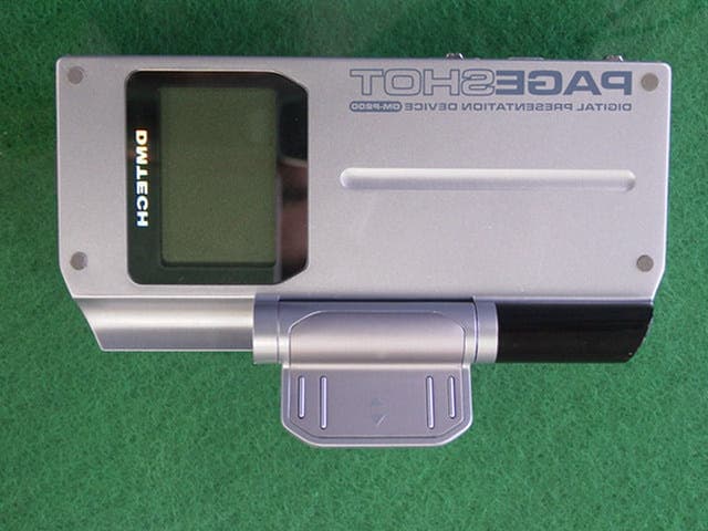
Click to zoom
Application Details
- Equipment Class
- JBP - Part 15 Class B Computing Device Peripheral
- Date of Grant
- Jul 07, 2003
- Application Purpose
- Original Equipment
- Date of Application
- Jul 07, 2003
- Equipment Note
- DIGITAL PRESENTATION DEVICE
- Company
- DM Technology Co., Ltd.
- Country
- South Korea
Documents & Files
Document Text
Text extracted from the exhibit documents filed with the FCC. Open a document above to read the original.
Users Manual
Content PageShot 1. PageShot Overview Overview 6 Package Contents 7 Part Names 8-11 Product Features 12 System Requirements 12 PageShot Specifications 12 2. Connecting PageShot Connecting the Power 14 - Installing 14 - Using the Adaptor 14 Connecting the Earphones 14 Connecting PageShot to a TV/(Projector) 15 Connecting PageShot to a Computer 15 3. Using PageShot Turning PageShot On 18~19 - Configuring NTSC/PAL 19 Holding Remote Control Operations (HOLD Button) 19 Disabling Video Out While Playing MP3’s 19 Selecting the PageShot Menu 20-21 - The PageShot Menu Icons 21 Using PRESENTATIONS 21-27 - Playing a Presentation 22 - Editing a Presentation 24-25 - Previewing Presentation File Images, Configuring the Presentation Start File 25-26 - Deleting a Presentation, Configuring the Start Path 27 Using JPEG 28-33 - Viewing JPEG Images in STILL CUT 29-30 - Viewing JPEG Images in SLIDE SHOW 31 - Viewing JPEG Images in STILL CUT 29-30 - Viewing JPEG Images in THUMBNAIL 32 - Deleting a JPEG image, Configuring the JPEG Start Path 33 Using MP3 33-37 - Playing MP3 Files 35 - Skipping a Music File, Adjusting the Volume 35 - Repeating, Deleting, Configuring the MP3 Start Path 36-37 Using VOICE 37-41 - Recording a Voice File, Playing a Voice File 38 - Exploring the Playback Location in a Voice File, Adjusting the Volume 39 - Repeating, Deleting a Voice File 40 - Configuring the Start Path 41 Using SETUP 41-53 - The PageShot Menu Icons 42 - Upgrading the Firmware 42-43 - Formatting the Memory 44 - Viewing Information 45 - Adjusting the Horizontal/Vertical Location of the Screen 46 - Configuring the PageShot Device 46 - Configuring the Start mode 47-48 - Muting the Sound 48-49 - Configuring the SLIDE SHOW Page Interval 49 - Configuring POWER SAVE 50 - Configuring Internal and External Memory 51 - Configuring the Video Out Signal (NTSC/PAL) 52 - Using External Memory 53 4. Using Applications Installing the USB Driver 56-61 - Windows 98 Second Edition 56-58 - Windows Millennium Edition 58 - Windows 2000 59-61 - Windows XP 61 Checking the Connectivity 62-63 Safely Removing PageShot After Use 63-64 Installing the PAGESHOT File Manager 65-66 Using the PAGESHOT File Manager 66-84 - Running the PAGESHOT File Manager 67 - Icon Functions 68 - Detailed Description of Functions 69-84 FORMATTING PAGESHOT 69 CONVERTING A POWERPOINT FILE TO JPEG 69-70 IMAGE FORMAT CONVERSION AND RESIZING 71-72 SCREEN CAPTURING 73-74 PLAYING A VOICE FILE 75 EDITING THE INITIALIZATION FILE 76-77 EDITING A PRESENTATION FILE 78-81 VIEWING THE DETAIL LIST 81 VIEWING THE THUMBNAIL LIST 81 INFORMATION 81 Copying Files to PageShot 82 Renaming a File 83 Deleting a File 84 Configuring the Language 84 Configuring the Image Size Depending on the TV Output 84 5. Using PAGESHOT File2 JPEG 85 - Running PAGESHOT File2 JPEG 85 - Icon Functions 86 - Detailed Description of Functions 87 Selecting the File Format 87 Downloading 87 Uploading 88 Deleting 89 Updating 89 Formatting PageShot 89 Page 6 PageShot Overview Package Contents Part Names Product Features System Requirements PageShot Specifications 1. PageShot Overview Overview PageShot is a portable presentation device that enables the giving of presentations without the need for other equipment such as a laptop computer. Using PageShot, a presentation can be held anywhere that a display device such as a TV or projector is present. PageShot provides functions for playing presentations created on a computer, playing MP3 files, and recording. By connecting to a computer via USB, you can easily create, edit, and save presentation files. It will greatly enhance your efficiency and add value to your business Page 7 Package Contents Page 8 Part Names Front View [LCD Display Panel]: This displays the operating status [Main Body] [Remote Control] Back View - CARD EJECT: Removing Compact Flash Memory. Page 9 Side View (Top) - DC Adaptor: Connected to the power. - REC Button: Used for voice recording - I/O Connect Cover - Status LED: Shows the status of the unit. * Amber: when booting. * Green: when in operation. * RED: when recording. * Green Blinking: When transmitting or receiving data through the USB connection. - Earphone Jack - A / V Output: A / V output port - USB: A data communication port that is used for transmissitting data with a computer. Side View (Bottom) - Battery Compartment Cover Side (Left) - Microphone - Compact Flash Memory Slot - HOLD Button - POWER Button - MP3/VIDEO: MP3/VIDEO Configuration Button Page 10 Front View of the Remote Control Laser Lens Direction key SELECT LASER REC MENU Direction key PLAY / PAUSE STOP / RETURN Battery MENU: Turns the menu on or off Direction key: Moves around the menu SELECT: Makes a selection in the menu LASER: Turns the laser beam on and off PLAY / PAUSE: Play / Pause STOP / RETURN: Stop / Return REC: Record Notice. Please take care never to point the laser pointer at a person. Note. Press the (icon) button on the PageShot initialization screen to select the appropriate video output type (NTSC / PAL). Page 11 Using the remote control for the first time: 1. Open the battery door by pulling the under-side of the remote control to open the battery compartment cover. 2. Insert and align the battery with the + and - symbols in the battery compartment. 3. Slide and close the battery compartment cover. Note. The remote control battery is a CR2032 3 Volt Lithium Cell. Page 12 Product Features - Windows 98, ME, 2000, and XP compatible - Automatic conversion of PowerPoint slides into the PageShot presentation format - USB plug-in support - Multi image folder support - Slide preview function support - Extended memory support - MP3 player function support - Recording function function System Requirements CPU : Pentium Memory : 64M OS : Windows 98, ME, 2000, and XP Peripheral I / O : USB Port PageShot Specifications Image Resolution 640 * 440 (NTSC) 640 * 500 (PAL) Image Format JPEG Audio Format MP3 Voice Format G.723 Storage Capacity Image – About 1000 image files MP…
Text truncated - open the document above for the full version.
Users Manual
Page 46 Adjusting the Horizontal/Vertical Location of the Screen You can adjust the horizontal and vertical location of the output screen. 1. In the SETUP SCREEN, Press the (icon) button. If you press the button in the Setup Screen, the Setup Screen appears. 2. Adjust the location of the screen by using the (icon) buttons. 3. Press the (icon) button. This moves to the SETUP menu. Configuring the PageShot Device You can configure the PageShot operation settings. 1. In SETUP DEVICE, Press the (icon) button. If you press the button in the Setup Device, the Setup Device screen appears. Configured value Selectable list Value to configure [SETUP DEVICE Screen] Page 47 Item to change configuration Configured value Value to configure [SETUP DEVICE LCD Screen] Configuring the Start Mode You can configure the Run mode when PageShot is on. 1. Press the (icon) button. If you press the button in Setup Device icon of the PageShot menu, the Setup Device screen appears. 2. Move to START MODE by using the (icon) buttons. 3. Press the (icon) button. The configurable list for the selected item appears. 4. Move to the value you wish to configure by using the (icon) buttons. Page 48 1. N/A : Plays the TITLE IMAGE, and the TITLE AUDIO 2. JPEG : Plays a JPEG slide show. 3. MP3 : Plays an MP3 file. 4. VOICE : Plays a Voice file. 5. PRJ : Plays the presentation file. 5. Press the (icon) button to configure. If you press the (icon) button, the item list disappears. 6. Press the (icon) button to save the changes and return to the SETUP menu. When you select JPEG, MP3, and VOICE, the files in the configured Start path are played. When you select PRJ, the configured presentation file is played. For information on the path and file configuration, refer to "Configuring the Start Path" in each corresponding chapter and "Configuring the Presentation Start File ". Muting the Sound You can decide whether to play a configured MP3 file while playing a presentation. 1. Press the (icon) button. If you press the button in the Setup Device icon of the PageShot menu, the Setup Device screen appears. 2. Move to AUDIO MUTE by using the (icon) buttons. 3. Press the (icon) button. The configurable list for the selected item appears. 4. Select the value to configure by using the (icon) buttons. 1. ON Plays the configured MP3 file. 2. OFF Does not play the configured MP3 file. Page 49 5. Press the (icon) button to make the selection. If you press the (icon) button, the item list disappears. 6. Press the (icon) button to save the changes and return to the SETUP menu. Note. This configuration is not relevant to playing MP3 and VOICE files. Configuring the SLIDE SHOW Page Interval You can configure the period of time for displaying an image while running the JPEG SLIDE SHOW. 1. Press the (icon) button. If you press the button in Setup Device icon in the PageShot menu, the Setup Device screen appears. 2. Move to JPG_DELAY by using the (icon) buttons. 3. Press the (icon) button. You can change the time interval between pages. (from 1 to 59 seconds) 4. Press the (icon) button to save the changes and return to the SETUP menu. Page 50. Configuring POWER SAVE 1. Press the (icon) button. If you press the button in Setup Device icon of the PageShot menu, the Setup Device screen appears. 2. Move to POWER SAVE by using the (icon) buttons. 3. Press the (icon) button. The configurable list for the selected item appears. 4. Move to the value to configure by using the (icon) button. ON: Turns off the power when there has been no operation for a predetermined time. OFF: Does not turn off the power. 5. Press the (icon) button to select. If you press the (icon) button, the item list disappears. 6. Press the (icon) button to save the changes and return to the SETUP menu. Page 51. Configuring Internal and External Memory You can determine which memory type to use. 1. Press the (icon) button. If you press the button in the Setup Device icon of the PageShot menu, the Setup Device screen appears. 2. Move to MEMORY by using the (icon) buttons. 3. Press the (icon) button. The configurable list for the selected item appears. 4. Move to the value you wish to configure by using the (icon) buttons. INTERNAL: This is to select PageShot’s internal memory. EXTERNAL: This is to select additionally installed external memory. 5. Press the (icon) button to select. When you select EXTERNAL configuration, it may take some time depending on the size of the external memory. If you press the (icon) button, the item list disappears. 6. Press the (icon) button to save the changes and return to the SETUP menu. Note. Only when the Compact Flash memory is installed, are the changes applied. For information on the installation procedures, refer to “Using External Memory”. Page 52. Configuring the Video Out Signal (NTSC/PAL) You can change the video signal according to the TV utilised. 1. Press the (icon) button. If you press the button in the Setup Device icon of the PageShot menu, the Setup Device screen appears. 2. Move to NTSC/PAL by using the (icon) buttons. 3. Press the (icon) button. The configurable list for the selected item appears. 4. Move to the value you wish to configure by using the (icon) buttons. NTSC: Change to NTSC type. (For the countries such as Korea, the United States, Japan, Canada, etc.) PAL: Change to PAL type. (For the Europe countries such as Germany, England, etc. as well as other countries such as China, Brazil etc.) 5. Press the (icon) button to select. If you press the (icon) button, the item list disappears. 6. Press the (icon) button to save the changes and return to the SETUP menu. Page 53. Using External Memory You can install additional memory by installing a Compact Flash (CF) card. 1. Installing External Memory Insert the card completely. Notice. If the card is inserted in the wrong way, the card will not be able to be inserted completely. Do not use force to insert the card. 2. Changing the Memory Changing the memory type from internal memory t…
Text truncated - open the document above for the full version.
Block Diagram
5 5 4 4 3 3 2 2 1 1 DD CC BB AA RFIC RFW24 U501 SAW RESONATOR RFW488R-A U503 POWER AMP BFG425W Q530 Power Amp ON/OFF Control Circuit Q531 DS550 Laser Diode SAW Correlator 4MHz U550 HT48R30A-1 Remocon MCU U502 RFW488C-A RESONATOR X550 KEY Matrix Antenna ANT501 U505 LDB212G4020C BALUN RF REMOCON 0.0 BLCOK DIAGRAM A4 11Tuesday, June 03, 2003 Title SizeDocument NumberRev Date:Sheet of TX_DATAACT ACT Power Amp ON/OFF 5 5 4 4 3 3 2 2 1 1 DD CC BB AA Interface Interface J202 J203 Connector Connector TMS320DSC21 U201A CLOCK 27MHz OSC201OSC202 48MHz CLOCKRESET Circuit SDRAM U204 U202 NOR_FLASH U203 NAND_FLASH 39VF160 K9F128U0M K4S643232 CFC Connector JP201 MAIN BOARD 0.0 BLOCK DIAGRAM A4 11Tuesday, June 03, 2003 Title SizeDocument NumberRev Date:Sheet of LCD_DATA Remocon_Data Power HOLD/OFF Audio Composite_Video USB_Data NTSC_PAL Select HOLD Select Analog_3.3V Digital_1.8V Digital_3.3V 5 5 4 4 3 3 2 2 1 1 DD CC BB AA DC JACKBattery Terminal J1 J4 POWER IC (TPS61107) U2 AUDIO CODEC IC (TLV320AIC23PW) U1 (KM4100) VIDEO AMP IC U4 AV JACK J8 JP1 USB Connector J7 LCD Connector J5 RF Connector (12MHz) X-TAL Q1 SW3 POWER ON/OFF Switch Interface Connector J3 Connector Interface J2 SW1 HOLD S/W SW2 NTSC_PAL S/W U5,U6 ESD Protection RF Receiver MK1 C-MIC I/O BOARD 0.0 BLOCK DIAGRAM A4 11Tuesday, June 03, 2003 Title SizeDocument NumberRev Date:Sheet of AUDIO L,R Composite Composite_a Audio LCD_Data HOLD Select (HOLD_d) NTSC_PAL Selecct (NTSC_PAL_d) Power Enable ONA_IN_a Power Supply Input Data Output USB_Data IR_a ONA_OUT_a Analog_3.3VDigital_3.3VDigital_1.8V Analog_3.3V Digital_3.3V Digital_1.8V 5 5 4 4 3 3 2 2 1 1 DD CC BB AA SAW RESONATOR ANT601 Antenna U605 LDB212G4020C BALUN U603 RFIC U601 RFW488R-A RFW488C-A RFW24 U602 SAW Correlator U630 Comparator OP Amp LM2903 MUX NC7SZ19 U604 RF CON JP601 RF RECEIVER 0.0 BLOCK DIAGRAM A4 11Tuesday, June 03, 2003 Title SizeDocument NumberRev Date:Sheet of DATA IO RSSI (CAP)MUX Enable Data Output Digital_3.3V
Operational Description
Form Letters1 OPERATIONAL DESCRIPTION The Hanhntek wireless mouse utilizes a 27MHz intentional radiator. The wheels & buttons provide input to IC V741CC60 which in turn provides modulating pulses to the intentional radiator.
Schematics
5 5 4 4 3 3 2 2 1 1 DD CC BB AA Easys-00051.6 ANALOG_TOP A4 16Thursday, June 12, 2003 Title SizeDocument NumberRev Date:Sheet of power ONA_IN_a LBO1_a ONA_OUT_a LBO2_a ESD_PWR_SW usb&ir&lcd IR_a ATTACH_a USB_Dminus_a USB_Dplus_a R_W_a DB_a[7..0] AO_a Enable_a nCSL_a video Composite_a Audio_L Audio_R interface ONA_OUT_a BDX_a BCLKR_a ONA_IN_a nCS_a BFSX_a SDA_a BFSR_a LBO1_a SCL_a BDR_a DB_a[7..0] Composite_a ATTACH_a USB_Dplus_a USB_Dminus_a Enable_a AO_a R_W_a IR_a nCSL_a LBO2_a ESD_PWR_SW audio BFSX_a BDX_a BFSR_a SDA_a nCS_a BCLKR_a BDR_a SCL_a AUDIO_L AUDIO_R LHPOUTRHPOUT DB_a[7..0] nCSL_a 5 5 4 4 3 3 2 2 1 1 DD CC BB AA 1-2: SHORT -> MODE0 I2C 1-2: OPEN -> MODE1 SPI JACK JACK Easys-00051.6 AUDIO A4 26Thursday, June 12, 2003 Title SizeDocument NumberRev Date:Sheet of DIN DOUT LRCIN LROUT RHPOUT nCS MICIN MICBIAS LHPOUT BCLK SDIN SCLK D3_3V A3_3V D3_3V R13 2.2k MK1 OB-20940 1 2 U1 TLV320AIC23PW 1 2 3 4 5 6 7 8 9 10 11 12 13 1415 16 17 18 19 20 21 22 23 24 25 26 27 28 BVDD CLKOUT BCLK DIN LRCIN DOUT LRCOUT HPVDD LHPOUT RHPOUT HPGND LOUT ROUT AVDDAGND VMID MICBIAS MICIN RLINEIN LLINEIN nCS MODE SDIN SCLK XTI/MCLK XTO DVDD DGND L12.2uH(2012) L22.2uH(2012) C2 100uF/6.3V R6100 C1 100uF/6.3V R7100 R12 100K C6 103 C5 10uF/6.3V C12105 C3103 BD1BK2125HS102 R4100 Q1 12MHz C14 22uF/6.3V R8 47k C4103 C7103 C9103 C8 22uF/6.3V C10 27pF C11 27pF R5100 C13 104 BFSX_a BDX_a BFSR_a SDA_a nCS_a BCLKR_a BDR_a SCL_a AUDIO_L AUDIO_R 5 5 4 4 3 3 2 2 1 1 DD CC BB AA Ref No:31~50(R,L,C) Ref No:31~50(R,L,C) Easys-00051.6 Interface_Analog A4 36Thursday, June 12, 2003 Title SizeDocument NumberRev Date:Sheet of B_a DB_a2 DB_a7 DB_a4 DB_a1 DB_a5 DB_a[7..0] DB_a6 DB_a0 DB_a3 R_a G_a A3_3V D3_3V D3_3V D1_8V D3_3V P1 B_a 1 1 P2 G_a 1 1 R33 10k P3 R_a 1 1 SW2 NTSC_PAL 3 2 R34 100k R31 10k U5 SM6503AD 1 2 34 5 6 DIO1 DIO2 DIO3DIO4 VSS DIO5 J2 CON22 1 2 3 4 5 6 7 8 9 10 11 12 13 14 15 16 17 18 19 20 21 22 J3 CON22 1 2 3 4 5 6 7 8 9 10 11 12 13 14 15 16 17 18 19 20 21 22 U6SM6503AD 123 456 DIO1DIO2DIO3 DIO4 VSS DIO5 SW1 HOLD 3 2 C31 104 C32 47p C33 104 R32 100k C35 104 C36 47p C37 104 USB_Dminus_a ATTACH_a USB_Dplus_a SCL_a SDA_a nCS_a BCLKR_a BFSR_a BDX_a BDR_a BFSX_a DB_a[7..0] Composite_a R_W_a IR_a AO_a ONA_IN_a LBO1_a ONA_OUT_a Enable_a nCSL_a LBO2_a ESD_PWR_SW 5 5 4 4 3 3 2 2 1 1 DD CC BB AA Ref No:51~80(R,L,C) Ref No:51~70(R,L,C) TPS61107 Easys-00051.6 POWER A 46Tuesday, June 17, 2003 Title SizeDocument NumberRev Date:Sheet of A3_3V D3_3V D1_8VD1_8V C51 104 U2 TPS61107 1416 1 2 18 5 4 3 7 10 19 8 20 9 6 12 13 15 11 SWNSWP VBAT LBI SKIPEN ADEN EN nENPB LDOEN GND VOUT LDOIN FB LDOOUT LDOSENSE nLBO1 nLBO2 PGOOD PGND C53 104 L4210uH +C65 22uF/6.3V C64 104 +C56 22uF/6.3V C61 220uF/6.3V D2 KDS160E J1 DC_Jack 1 2 3 BD51 BK2125HS102 +C60 22uF/6.3V R54 1.8M R58 270k L4122uH R700R67510k C58 100uF/6.3 C62 104 C57 2.2uF/6.3 L44000(2012) C63 104 R68 1M C52 104 R64 1M + C54 47uF/6.3V R65 1M SW3 SW_Tact 1 2 R66 1M J4 INPUT 2 1 R56 470k L4310uH C59 331 C55 104 ONA_IN_a LBO1_a LBO2_a ONA_OUT_a ESD_PWR_SW 5 5 4 4 3 3 2 2 1 1 DD CC BB AA Ref No:81~120(R,L,C) Ref No:81~120(R,L,C) Easys-00051.5 USB/IR/LCD A 56Thursday, June 12, 2003 Title SizeDocument NumberRev Date:Sheet of DB_a4 DB_a7 DB_a5 DB_a1 DB_a2 DB_a0 DB_a3 DB_a6 D3_3V D3_3V C84474 R95 100 C85474 R96 100 C86474 R86 100 R101 10k R87 47k BD81BK2125HS102 BD82BK2125HS102 BD83BK2125HS102 +C91 10uF/6.3V R99 100 J7 CON28 1 2 3 4 5 6 7 8 9 10 11 12 13 14 15 16 17 18 19 20 21 22 23 24 25 26 27 28 VDD C86 VSS V0 V4 V3 V2 V1 CAP2- CAP2+ CAP1+ CAP1- CAP3+ VOUT VSS D7 D6 D5 D4 D3 D2 D1 D0 nRD,E nWR,R/nW AO nRES nCS R82 10K R98 100 J5 CON3_RF 1 2 3 R88 47K R8422 R833.3K JP1 USB 1 2 3 46 5 1 2 3 46 5 R97 100 C871uF/25V R8522 C901uF/25V R89 100R90 100 C881uF/25V R91 100R92 100 C81 104 C82474 R93 100 C83474 R94 100 R_W_a DB_a[7..0] AO_a Enable_a IR_a USB_Dplus_a USB_Dminus_a ATTACH_a 5 5 4 4 3 3 2 2 1 1 DD CC BB AA Ref No:121~140(R,L,C) Ref No:121~140(R,L,C) Easys-00051.5 Video A 66Thursday, June 12, 2003 Title SizeDocument NumberRev Date:Sheet of A3_3V C121 104 J8AV Jack 1 3 4 2 R124 4.7k C125 220uF/6.3V C123 221 C124 221 L121 3.3uH(1608) R126 75 R125 4.7K U4 KM4100 43 1 2 5 -IN+IN OUT -Vs Vcc C122 10uF/6.3V BD121 BK2125HM121 Audio_L Audio_RComposite_a 5 5 4 4 3 3 2 2 1 1 DD CC BB AA Ref No:201~210(R,L,C) Ref No:201~210(R,L,C) Ref No:200~ Ref No:200~ Easys-00051.5 DIGITAL_TOP A4 18Thursday, June 12, 2003 Title SizeDocument NumberRev Date:Sheet of D_CFC Conn. CFC_nSTSCHG/BVD1 CFC_nREG CFC_RESET CFC_nWE CFC_nIOWR CFC_nIORD CFC_nCE2 CFC_nWAIT CFC_IREQ/RDY/BSY CFC_nCD1CFC_nCD2 CFC_nOE CFC_nCE1 CFC_A[10..0] CFC_D[15..0] flash_code EXMEM_A[20..1] Flash_nCE Flash_nOE Flash_nWE EXMEM_D[15..0] nRESET flash_data EXMEM_D[7..0] SSF_CLE SSF_ALE SSF_nWE SSF_nRE SSF_nCE SSF_nWP SSF_R/B sdram SDR_DQMLL SDR_DQMHL SDR_CS0 SDR_WE SDR_RAS SDR_DQMLH SDR_DQMHH SDR_A[14..0] SDR_DQ[31..0] SDR_CAS SDR_CLK SDR_CKE clk_reset M27XI M48XI nRESET interface_d ONA_IN_d ONA_OUT_d BDR_d BFSR_d BDX_d SDA_d nCS_d BFSX_d BCLKR_d DSP_BCLKX_d USB_Dminus_d USB_Dplus_d LBO1_d SCL_d AO_d Enable_d ATTACH_d IR_d B_d G_d R_d Composite_d DB_d[7..0] NTSC_PAL_d HOLD_d R_W_d nCSL_d LBO2_d dsc21 SSF_nWP FLASH_nOE FLASH_nWE FLASH_nCE SSF_R/B EXMEM_D[15..0] SSF_nCE EXMEM_A[20..1] nRESET USB_Dplus_d M48XI USB_Dminus_d M27XI SDR_WE SDR_CS0 SDR_DQMHL SDR_RAS SDR_CAS SDR_DQMLL SDR_A[14..0] SDR_DQMLH SDR_CLK SDR_CKE Composite_d SDR_DQMHH SDR_DQ[31..0] DB_d[7..0] IR_d R_W_d Enable_d SSF_nRE AO_d ATTACH_d SDA_d SCL_d BDX_d BDR_d BCLKR_d BFSR_d CFC_nOECFC_nWE CFC_nCE1CFC_nCE2 CFC_RESETCFC_nSTSCHG/BVD1CFC_nWAITCFC_nCD1CFC_nCD2 CFC_IREQ/RDY/BSY CFC_D[15..0] nCS_d ONA_IN_d ONA_OUT_d R_d G_d B_d LBO1 _d HOLD_d NTSC_PAL_d BFSX_d DSP_BCLKX_d CFC_A[10..0] SSF_CLE CFC_nIORD SSF_ALE CFC_nIOWR EXMEM_D[7..0] SSF_nWE CFC_nREG nCSL_d LBO2_d EXMEM_D[7..0] nRESET EXMEM_D[15..0] EXMEM_A[20..1] SDR_DQ[31..0] CFC_A[10..0]CFC_D[15..0] DB_d[7..0] SDR_A[14..0] nCSL_d nRESET 5 5 4 4 3 3 2 2 1 1 DD CC BB AA Receiver 4.0 2.4GHz RF REMOCON A4 11Tuesday, June 10, 2003 Title S…
Text truncated - open the document above for the full version.
Test Report
EMI TEST REPORT Emission of electromagnetic disturbance Test Report No. : ERI-FCC03-0042 Equipment : Digital presentation device Name of basic model : DM-P200 Family model : N/A Manufacturer :GUANGZHOU DEBAO YUCHANG ELECTRONICS CO.,Ltd Applicant : D.M. Technology Co., Ltd. Tested date : 2003. 6. 18 Issued date : 2003. 6. 19 Test results : PASS Test Standards : FCC Part 15 Subpart B (Class B) / Verification /digital devices & peripherals Test Procedure and Items: - AC Power line Conducted emissions measurement : ANSI C63.4-1992 - Radiated emissions measurement : ANSI C63.4-1992 Tested by: YOUNG-SIK, KIM Approved by: UK-CHO, RIM The results in this report apply only to the sample tested. This test report shall not be reproduced except in full, without the written approval of ERI Laboratory. ELECTROMAGNETIC RESEARCH INSTITUTE CONTENTS 1. CLIENT INFORMATION 2. LABORATORY INFORMATION 3. EQUIPMENT UNDER TEST INFORMATION(EUT) 3.1 Identification of the EUT 3.2 Additional information about the EUT 3.3 Peripheral equipment 4. CONTINUOUS DISTURBANCE VOLTAGE, MAIN TERMINAL 4.1 Operating environment 4.2 Test set-up and test procedures5 4.3 Test instrument 4.4 Test results 5. RADIATED DISTURBANCE : 30MHz – 1000MHz 5.1 Operating environment 5.2 Test set-up 5.3 Test conditions 5.4 Test instrument 5.5 Test results(Test mode: play mode) APPENDIX (N/A) ELECTROMAGNETIC RESEARCH INSTITUTE 1. CLIENT INFORMATION The EUT has been tested by request of : Company : D.M. Technology Co., Ltd. Address : 5 th F1., Mando Bldg. 730 Dang-dong, Gunpo, Kyunggi-do, Korea 435-010 Name of contact : TONG JIN, PARK Telephone : + 82-31-451-4526 Facsimile : + 82-31-451-4520 2. LABORATORY INFORMATION The 10m full-anechoic chamber and/or EMC facilities are used for these testing. These facilities were accredited by KOLAS, EK, MIC of Korea and FCC of USA. Address ELECTROMAGNETIC RESEARCH INSTITUTE. 66-6, JEIL-RI, YANGJI-MYUN, YOUNGIN-CITY, KYUNGGI-DO, KOREA Telephone No. : +82-31-336-1186~7 Facsimile No. : +82-31-336-1184 Registered No. KOLAS : 111 EK : J MIC : KR0030 FCC Filing No. : 302567 3. EQUIPMENT UNDER TEST INFORMATION(EUT) 3.1 Identification of the EUT Type of equipment : Digital Presentation device Model name : DM-P200 Brand name : ALVA Manufacturer : GUANGZHOU DEBAO YUCHANG ELECTRONICS CO.,Ltd Address : 36-1 bangjiang Village East, Shilian Road, Shiji Town, Panyu Qu, Guangzhou City, Guangdong, China Telephone : + 86-20-3456-1861 Facsimile : + 86-20-3456-1832 Country of origin : CHINA ELECTROMAGNETIC RESEARCH INSTITUTE Rating : 120V, 60Hz 3.2 Additional information about the EUT Class B, Family model list; (N/A) 3.3 Peripheral equipment Defined as equipment needed for correct operation of the EUT. Description Model No. Serial No. Manufacture AC/DC adaptor ADP-60DB MJD0124008510 Delta electronnics Co., Ltd. Note PC CM2080 5Y17JNZ9R622 LG Printer C6427A CN13V1B1RY HP AC/DC power supply STP032030E N/A D.M. Technology Co., Ltd. Earphone N/A N/A “ Smart card N/A N/A Transcend 4. CONTINUOUS DISTURBANCE VOLTAGE, MAIN TERMINAL ELECTROMAGNETIC RESEARCH INSTITUTE : Frequency range 0.15 MHz to 30 MHz 4.1 Operating environment Temperature : 23.0 Relative Humidity : 48.0 % 4.2 Test set-up and test procedures The mains terminal disturbance voltage was measured with the equipment under AC Main LISN Printer EUT Note pc LISN Earphone AC/DC adaptor AC/DC adaptor ELECTROMAGNETIC RESEARCH INSTITUTE test(EUT) in a shield room. The EUT was connected to an artificial mains network(LISN) placed on the floor. The EUT was placed on non-metallic table 0.4m above the metallic, grounded floor. The distance to other metallic surface was at least 0.8m. Amplitude measurements were performed with a quasi-peak detector and an average detector. Operation condition: During the test, we played on the record file. 4.3 Test instrument Instrument Model No Serial No. Makers Next cal.date Used Test receiver ESCS30 100021 R&S 2004. 1. 24 ESH3-Z5 827246/008 R&S 2004. 3. 19 L.I.S.N. ESH3-Z5 831887/018 R&S 2004. 3. 19 Shield room 8 6 3.3m/H - - - 4.4 Test results Date of test: Jun 18, 2003. An overview sweep performed with peak detector & average detector are included in the report as test reports. Frequency Tested LISN Meter Range Freq. Reading Limits Margin QP AV QP AV QP AV [MHz] [MHz] [dBuV] [dBuV] [dBuV] 0.177 N 30.5 23.1 65.6 55.6 0.177 N 0.216 N 31.4 23.2 63.0 53.0 0.216 N 0.15-30 0.234 N 31.9 24.8 62.3 52.3 0.234 N 0.321 N 31.7 22.8 59.6 49.6 0.321 N 0.375 N 34.7 27.5 58.3 48.3 0.375 N 0.465 N 39.9 31.5 56.5 46.5 0.465 N 1.890 N 30.7 21.7 56.0 46.0 1.890 N 2.040 N 30.7 22.8 56.0 46.0 2.040 N 2.680 N 30.8 26.5 56.0 46.0 2.680 N 2.980 N 32.1 27.8 56.0 46.0 2.980 N * <5 : mean less than 5dB * Other frequency keep over 20dB margin. ELECTROMAGNETIC RESEARCH INSTITUTE [Hot line] [Neutral line] 5. RADIATED DISTURBANCE ELECTROMAGNETIC RESEARCH INSTITUTE : 30MHz – 1000MHz 5.1 Operating environment Temperature : 22.0 Relative Humidity : 55.0 % 5.2 Test set-up The frequency range investigated was 30 MHz to 1000 MHz. All readings are quasi-peak unless stated otherwise. The half-wave dipole antenna was tuned to the frequency found during Preliminary radiated measurements. The EUT, support equipment and Interconnecting cables were re-configured to the set-up to the producing the Maximum emission for the frequency and were placed on top of a 0.8 meter High non-metallic 1 X 1.5 meter table. The EUT, support equipment, and interconnecting cables were re-arranged and manipulated to maximize each EME emission. The turntable containing the system was rotated the antenna height was varied 1 to 4 meters and stopped at the azimuth or height producing the maximum emission. And this device(EUT) was tested in 3 orthogonal planes. The antenna measured both horizontal and vertical polarization. ELECTROMAGNETIC RESEARCH INSTITUTE <General test set-up for radiated emissions> 5.3 Operation Conditions During the test, we played on the record file. 5.4 Test instrument Instrument Model No. Ser…
Text truncated - open the document above for the full version.
Contact Information
Applicant
Myeong-Ho Kim
Test Firm
EMC Compliance LTDMin Seok Chung
Technical Specifications
| # | Rule Parts | Frequency Range | Power Output |
|---|---|---|---|
| 1 | 15B | - | - |
Other Applications from DM Technology Co., Ltd.
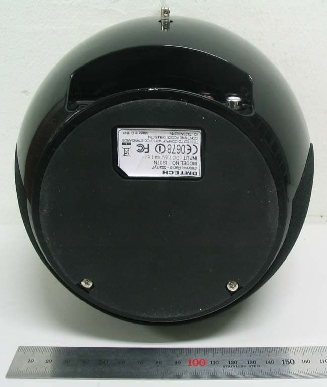
Q9MIS07N
Jan 30, 2008Internet Radio device
Equipment Class
DTS - Digital Transmission System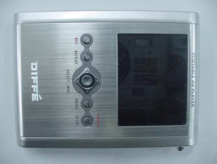
Q9MDM-AV7
Nov 25, 2004Portable Mulitmedia Player
Equipment Class
JBP - Part 15 Class B Computing Device Peripheral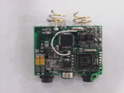
Q9MDM-FA60
Oct 28, 2004MP3 PLAYER
Equipment Class
JBP - Part 15 Class B Computing Device Peripheral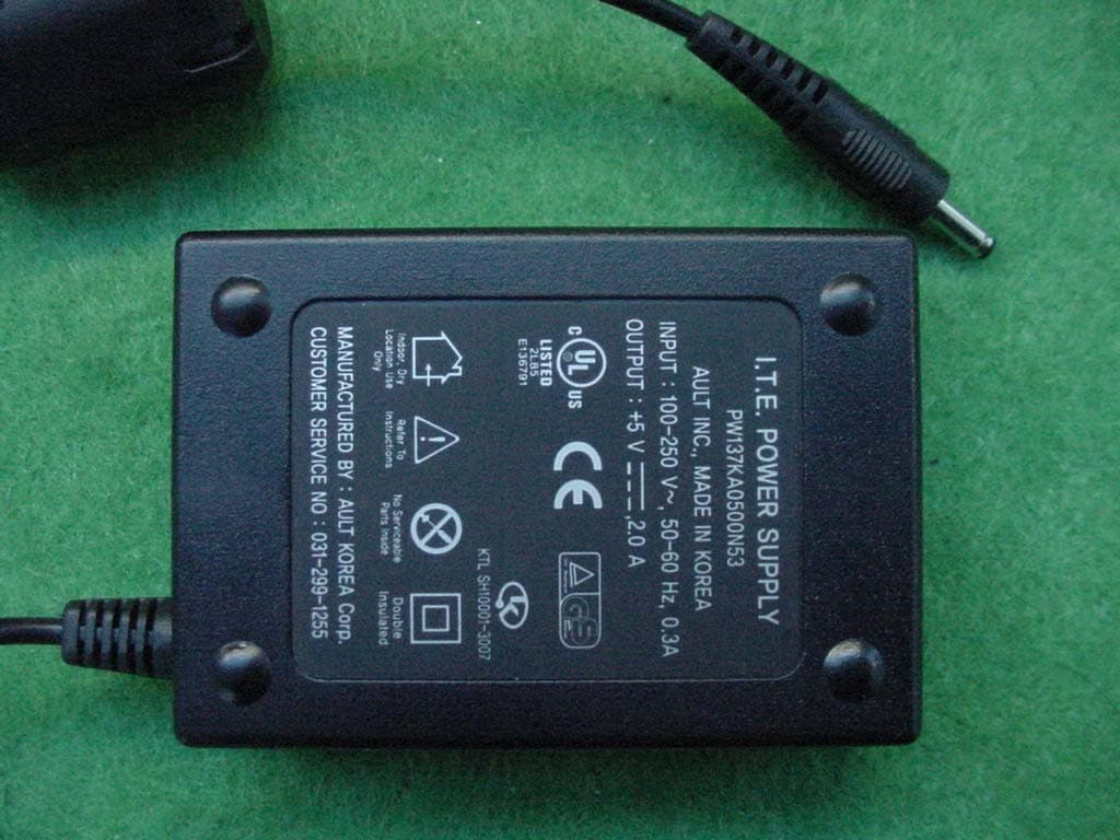
Q9MDM-AV10
Feb 23, 2004DIGITAL PRESENTATION DEVICE
Equipment Class
JBP - Part 15 Class B Computing Device Peripheral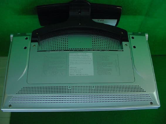
Q9MDML-3017W
Aug 18, 2003Digital presentation device
Equipment Class
JBP - Part 15 Class B Computing Device Peripheral