Q9MDML-3017WDigital presentation device
DM Technology Co., Ltd.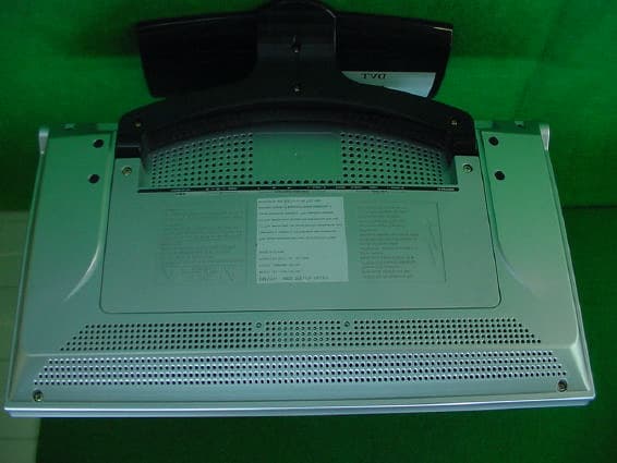
Click to zoom
Application Details
- Equipment Class
- JBP - Part 15 Class B Computing Device Peripheral
- Date of Grant
- Aug 18, 2003
- Application Purpose
- Original Equipment
- Date of Application
- Aug 18, 2003
- Equipment Note
- Digital presentation device
- Company
- DM Technology Co., Ltd.
- Country
- South Korea
Documents & Files
Document Text
Text extracted from the exhibit documents filed with the FCC. Open a document above to read the original.
Users Manual
Cover 17” WIDE TFT LCD TV Before using this product, please read the security instructions first and bear them in mind when using the product. Security Instructions To prevent damage, which may result in fire or electric shock hazard, do not expose this appliance to rain or moisture. This product has been designed and manufactured for home and office use. Any problems with the TV will not be valid for the service agreement when the product has been used for purposes other than home or office use, even if the warranty period has not expired. This product is manufactured and sold for domestic use only. The company shall not be held liable for any malfunction of the TV, if it is used anywhere else except the domestic market. Additionally, TV support can only be provided for the domestic market. 1P Warning! Important Safety Instructions CAUTION: TO REDUCE THE RISK OF ELECTRIC SHOCK, DO NOT REMOVE COVER (OR BACK). NO USER SERVICEABLE PARTS INSIDE. REFER SERVICING TO QUALIFIED SERVICE PERSONNEL. This symbol indicates high voltage is present inside. It is dangerous to make any kind of contact with any inside part of this product. This symbol alerts you that important literature concerning operation and maintenance has been included with this product. Note to CATV system installer: This reminder is provided to call CATV system installer’s attention to Article 820-40 of the National Electrical Code (Section 54 of Canadian Electrical Code, Part I), that provides guidelines for proper grounding and, in particular, specifies that the cable ground shall be connected to the grounding system of the building as close to the point of cable entry as practical. Caution: FCC/CSA regulations state that any unauthorized changes or modifications to this equipment may void the user’s authority to operate it. Caution: To prevent electric shock, match the wide blade of plug to the wide slot, and fully insert the plug. Attention: pour eviter les chocs electriques, introduire la lame le plus large de la fiche dans la borne correspondante de la prise et pousser jusqu’au fond. Important: One Federal Court has held that unauthorized recording of copyrighted TV programs is an infringement of U.S. copyright laws. Certain Canadian programs may also be copyrighted and any unauthorized recording in whole or in part may be in violation of these rights. To prevent damage which may result in fire or electric shock hazard, do not expose this appliance to rain or moisture. Important Safety Information Always be careful when using your TV receiver. To reduce the risk of fire, electrical shock, and other injuries, keep these safety precautions in mind when installing, using, and maintaining your machine. • Read all safety and operating instructions before operating your TV. • Keep the safety and operating instructions for future reference. • Heed all warnings on the TV receiver and in the operating instructions. • Follow all operating and use instructions. • Unplug the TV receiver from the wall outlet before cleaning. Use a damp cloth; do not use liquid or aerosol cleaners. • Never add any attachments and/or equipment without approval of the manufacturer. Such additions can increase the risk of fire, electric shock, or other personal injury. • Do not use the TV receiver where contact with or immersion in water is a possibility, such as near bath tubs, sinks, washing machines, swimming pools, etc. • Do not place the TV on an unstable cart, stand, tripod, bracket, or table where it can fall. A falling TV can cause serious injury to a child or adult, and serious damage to the appliance. Use only with a cart, stand, tripod, bracket, or table recommended by the manufacturer or sold with the TV. Follow the manufacturer’s instructions when mounting the unit, and use a mounting accessory recommended by the manufacturer. Move the TV and cart with care. Quick stops, excessive force, and uneven surfaces can make the unit and cart unsteady and likely to overturn. • Provide ventilation for the TV receiver. The unit is designed with slots in the cabinet for ventilation to protect it from overheating. Do not block these openings with any object, and do not place the TV receiver on a bed, sofa, rug, or other similar surface. Do not place it near a radiator or heat register. If you place the TV receiver on a rack or bookcase, ensure that there is adequate ventilation and that you’ve followed the manufacturer’s instructions for mounting. • Operate your TV receiver only from the type of power source indicated on the marking label. If you are not sure of the type of power supplied to your home, consult your appliance dealer or local power company. • Use only a grounded or polarized outlet. For your safety, this TV is equipped with a polarized alternating current line plug having one blade wider than the other. This plug will fit into the power outlet only one way. If you are unable to insert the plug fully into the outlet, try reversing the plug. If the plug still does not fit, contact your electrician to replace your outlet. • Protect the power cord. Power supply cords should be routed so that they won’t be walked on or pinched by objects placed on or against them. Pay particular attention to cords at plugs, convenience receptacles, and the point where they exit from the unit. • Unplug the TV from the wall outlet and disconnect the antenna or cable system during a lightning storm or when left unattended and unused for long periods of time. This will prevent damage to the unit due to lightning and power-line surges. • Avoid overhead power lines. An outside antenna system should not be placed in the vicinity of overhead power lines or other electric light or power circuits or where it can fall into such power lines or circuits. When installing an outside antenna system, be extremely careful to keep from touching the power lines or circuits. Contact with such lines can be fatal. • Do not overload the wall outlet or extension cords. Overloading can res…
Text truncated - open the document above for the full version.
Operational Description
59P Specifications The exterior design and the product specifications are subject to be changed without prior notice due to improvements in performance . This product is manufactured for domestic use. This product may not be used in countries whose television system type or power voltage is different. Model Screen Size 17”WIDE Viewable Screen Size Pixel Area Type LCD Pannel Viewing Angle Up/Down: 120 degrees Left/Right: 150 degrees VHF: Channel? ~ Channel ?? UHF: Channel ?? ~ Channel ?? CATV:??~?? Receiver / Channels Television Broadcasting System: NTSC Antenna Interface VHF, UHF : 75? Video Signal NTSC-M TV/VIDEO Video Type CVBS, S-VHS COMPONENT 720p, 480p, 1080i Horizontal Frequency 30~60 KHz PC Synchroni zation Vertical Frequency 56~75 Hz Color Quality 16,772,216 color Maximum Resolution 1280 X 768 Separation Signal TTL, Anode or Cathode Audio Out 5W x 2 / 5W x 2 (2 Way) Power Supply AC 120V,50/60Hz, DC12V/5A Power Consumption Maximum 160W Power Consumption When Power Saving Mode Less than 3W Dimension with Speaker/Monitor Weight 7.9 Kg Remote control, Battery (AAA), Owner’s Instructions, Power Cord, AC adapter, RF-Cables, Video/Voice Connectors. Accessories This device has been registered in regards to EMI for residential use. It may be used in all areas. 60P Apendix Standard Signal Mode Table A TFT LCD TV is configured to support the following 10 signal modes. A user can register up to 10 modes. Configure the PC display mode referring to the following table. For configuration procedures, refer to the Appendix of the PC manual. Resolution Horizontal Frequency (Khz) Vertical Frequency (Hz) Clock Frequency (Mhz) Polarity(H/V)
Schematics
4 5 CHASSIS GROUND. USING COLOR BAR SIGNAL WITH ALL CONTROLS AT NORMAL. 4. WAVEFORMS ARE MEASURED WITH SYNCHROSCOPE FROM POINT INDICATED TO 4 5 PCB USING COLOR BAR SIGNAL WITH ALL CONTROLS AT NORMAL. 4 3 22" 1/2F : FUSE RESISTOR 1/2W. 10W : CEMENT RESISTOR10W DRAWING BY : 4 1 mute : H O 4 3 APPROVED BY : MODEL NO. DMTechnology.CO,.LTD. OPTION 4 5 JUHWAN LEE 2003.07.01 CHASSIS NO. 4 3 TO INVERT BL_ON/OFF 4 6 Analog GND MSP3410G(NT/PAL/SECAM)MSP3420G(NT/PAL MN) JUHWAN LEE 2003.07.01 Digital GND O CHECKED BY : DESIGNED BY : 4 3 **NOTE** JAPANONLY DRAWING NO.DOMESTIC X 4 1 1. ALL RESISTORS 1/16W CARBON FILM RESISTOR JULESS OTHERISE LISTED 4 1 17LCD TV FOR USA 4 3 1/2R : METAL OR METAL OXIDE 1/2W. 1/2S : SOLID1/2W. MODEL (SS450) 17" 4 8 R902 BRIGHT 3. VOLTAGES ARE HEASURED WITH DVM FROM POINT INDICATED TO CHASSIS GROUND. R901 FIN. APPROVED BY : CAPACITANCE LESS THAN 1 ARE EXPRESS IN uF. AND GREATER THAN 1 IN OF. RESISTANCE UNIT IS IN OHM. K=1,000 M=1,000,000 2. ALL CAPACITORE ARE 50V CERAMIC CAPACITOR UNLESS OTHERWISE LISTED. USA/PALONLY X 4 5 6 9 SCHEMATIC DIAGRAM OF 17LCD TV (USA,7/1) OFF/ON (LG:400) 6 09 6 26 6 26 6 26 6 26 7 22 OPTION OPTION OPTION OPTION 7 7 7 8 7 18 7 18 TP159,TP160,TP161 MICOM EMULATOR TOP 3216 SIZE 7 18 7 22 <Doc> <RevCode> <Title> Custom 11 Thursday, July 31, 2003 TitleSize Document Number Rev Date: Sheet of DIGO9 CAPD19 DDC_SDA PS MD15 RD MAD0 MA3 MAD5 IR Pr DIGO23 DIGO21 VS_MP MD6 KEY1 AV2_L MD21 SDA SDA1 FP_PWC MCA18 DIGO18 DIGO14 DIGO6 INT MD9 MD13 CAPD22 VS DQM6 ALE CAPD14 MA8 AV1_R MD8 DIGO4 MD11 FP_PWC MD29 MD18 DE MD4 CAPD17 S_VHS_C Pr DIGO3 MD4 MD10 MD29 ESCL MD6 DIGO12 MD16 MAD0 MA8 SDA1 IR MCA17 MD31 DIGO11 CAPD15 R_SPK CVBS_OUT DIGO10 KEY1 SCL MD25 J_Pr MA9 DIGO22 MCA12 L_SPK MD16 MD0 MD25 MD1 CAPD7 MA1 MD27 VS_PIP MD12 CAPD9 MD21 DDC_SCL MA4 MD11 MAD7 HS_PIP MA3 MA2 DQM7 DIGO19 DIGO1 MD20 DIGO1 CAPD6 J_Pr MAD2 Pb MCA16 MD5 KEY0 DIGO19 MCA7 MAD3 AV1_R MCA6 MAD1 DIGO18 MD22 MD14 SCL DIGO14 MD26 DIGO2 MCA16 DIGO13 MAD5 MA6 S_VHS_Y DIGO21 MD9 PC_SOUND_L MAD3 MD30 DIGO3 CAPD2 MCA15 MD5 CAPD16 DIGO6 MA7 AV1_L MD24 MAD6 DIGO2 MD28 MA5 MA1 MA0 MCA7 MD10 PC_SOUND_R CAPD3 MD20 CAPD13 MA4 ESDA MD22 DIGO9 S_VHS_Y MCA0 DIGO12 SCL1 L_SPK MD3 MD27 DIGO15 MD8 MAD1 DQM5 CAPD18 MD12 DIGO16 MAD4 DIGO7 CAPD21 MUX_CTL1 DIGO20 CAPD8 RESET MA0 MAD7 WR DIGO13 MD2 DIGO0 DIGO5 MD19 MAD4 MD19 MA2 CAPD20 MD13 DIGO15 MAD6 DIGO7 CAPD10 AD5 MA6 MCA12 MD14 CAPD12 DIGO17 MD26 SDA MD17 DIGO20 MUTE CAPD4 MD2 AV1_L AV2_R DIGO22 MAD2 CAPD11 DIGO23 Pb DIGO8 MD30 MD1 S_VHS_C CAPD23 MCA18 HS_MP MD7 MD7 CAPD0 R_SPK DIGO8 MA5 AV2_L MD28 DIGO16 CAPD5 PC_SOUND_R AV2_R Y DIGO4 MCA6 MA9 SCL RESET MD23 MD15 MCA17 MA7 MD3 DQM4 DIGO0 MD23 MCA15 CAPD1 DIGO10DIGO11 DIGO5 ST5V MD24 DIGO17 PC_SOUND_L MD18 MD17 MD0 MCA0 HS MD31 HS_OUT VS_OUT SC_CLK AFT SIF_OUT AV2_CVBS SDA1 SCL1 TV_CVBS AV2_CVBS MUX_CTL1 AV2_CVBS J_Y J_Pb J_Pb HDD_Pr HDD_Y HDD_Pb MUX_CTL2 AV2_CVBS1 AV2_CVBS1 AV2_CVBS2 AV2_CVBS2 HDD_Y HDD_Pb HDD_Pr HDD_CVBS_OUT ON_OFF SIF_OUT 33V SDA1 TV_CVBS_HDD SDA HDD_A_OUT_R TV_CVBS_HDD 5V BL_ON_OFF BRIGHT BRIGHT BL_ON_OFF _RESET _RESET HDD_A_OUT_R CONTROL_0 CONTROL CONTROL HDD_A_OUT_L HDD_A_OUT_L HDD_CVBS_IN MUX_CTL2 AFT MD42 MD34 MD49 MD53 MD62 MD44 MD33 MD32MD60 MD57 MD61 MD41 MD54 MD55 MD42 MD37 MD59 MD39 MD41 MD34 MD52 MD51 MD52 MD40 MD36 MD35 MD57 MD50 MD38 MD44 MD53 MD63 MD56 MD39 MD58 MD43 MD50 MD63 MD32 MD45 MD36 MD60 MD35 MD48 MD56 MD47 MD33 MD59 MD58 MD49 MD40 MD43 MD37 MD62 MD38 MD61 MD54 MD55 MD45 MD51 MD46 MD48 MD46 MD47 DQM3 DQM1 DQM0 DQM2 R_HP R_HP MCA3 MCA8 MCA14 MCA5 MCA11 MCA8 MCA13 MCA2 MCA1 MCA1 MCA4 MCA3 MCA9 MCA2 MCA9 MCA11 MCA13 MCA5 MCA14 MCA10 MCA4 MCA10 5V 5V 5V SCL1SDA1 HDD_COM DE B_OUT VS_OUT CAPD11 CAPD4 CAPD2 AD6 DQM1 MA4 CAPD18 SC_CLK CLK_PIP DQM6 DQM3 MA3 CAPD19 RDWRAD0 DQM7 DQM5 PSAD5 G_OUT CAPD17 AD2 CAPD5 AD1 CAPD14 CAPD13 CAPD7 HS_PIP R_OUT CAPD16 CAPD9 AD3AD7 5VDDM AD7AD6AD4AD2 HS_OUT AD4AD0AD1 MA8 MA1 INT DQM0 MA9 MA7 VCC2_5 HS_MP MA5 MA0 CAPD12 CAPD1 CLK_PIP VS_MP MA6 CAPD0 MA2 AD3 CAPD15 DQM4 ALE CAPD22 CAPD21 CAPD20 CAPD8 CAPD3 DQM2 CAPD10 CAPD6 CLK_MP CAPD23 VS_PIP 5V SCL1 SCL1 L_HP L_HP KEY0 ON_OFF ON_OFF 5V 5V J_Y Y HDD_COM HDD_A_IN_L HDD_A_IN_R SCLSDA A_OUT_R A_OUT_L TV_CVBS A_OUT_R A_OUT_L HDD_A_IN_RHDD_A_IN_L CONTROL_0 VCC3B 5V 3_3V VCC3B 12V VCC3B 8V VCC3A ST5V ST5V ST5V ST12V VCC3A 5V VCC3A AVCC3 ST5V VCC2_5 3_3V VCC3A 5V VCC3B VCC3AD ST5V VCC3AD VCC2_5 5V VCC3AD 8V ST5V 5V VCC3P 5V VCC2_5 VCC3 AVCC3 VCC3P VCC3AD ST12V ST5V ST5V VCC3 ST12V 5V ST5V 5V ST5V VCC3P 3_3V 5VDDM 33V HDD3V 3_3V HDD5V 5V HDD12V 12V HDD12V HDD5V HDD3V HDD5V HDD5V 5V VCC3 VCC3B VCC3A VCC3 VCC3P 12V C907 104 Q803 KIA78L05F 3 1 2 IN OUT G CD521uF 50V Q581 RC1117S33T(SOT223) 3 1 2 IN G OUT R1005100 C532222 R05010K C804 100UF 16V CS056P L207B-800 RH27 10 TP128 CS221uF 50V TP68 C55610uF 16V C566 472 L136 B-501(3216) RH150 Q002M27W401-80K 1234 5 6 7 8 9 10 11 12 13 14151617181920 21 22 23 24 25 26 27 28 29 303132 VPP A16A15A12 A7 A6 A5 A4 A3 A2 A1 A0 Q0 Q1Q2GNDQ3Q4Q5Q6 Q7 CE A10 OE A11 A9 A8 A13 A14 A17A18 VCC QP04KTC3875S-Y 1 3 2 R1012 10K Q881GM7130-3.3 1 2 3 4 5 IN OUT GND Feedback S/W TP29 CH16 4.7uF 50V R051 10K L901B-501(3216) C563 20P R5021608 C605 1uF 50V TP111 TP134 RS21 0 CM05 102 C906 104 CS28104 PD01 D-SUB JACK 1 6 2 7 3 8 4 9 5 10 11 12 13 14 15 . . . . . . . . . . . . . . . D802 MBRS340T3 CD63 4.7uF 50V R302 33 C517 101 RM1833A TP129 CS41 1uF 50V C606224 TP38 C904104 CH07 104 CS24102 C014 104 DZ006 KDZ5.6V L292B-800 C223 6.3V 120uF OS L592 B-501(3216) C586 100uF 10V TP176 CM53102 TP31 C1001 1000uF/16V CD13 104 R611 10 R262 1K QD50 BA7657F 1 2 3 4 5 6 7 8 9 10 11 1213 14 15 16 17 18 19 20 21 22 23 24 Red 1 input HD Sync signal detector Green 1 input GND Blue 1 input GND Red 2 input GND Green 2 input GND Blue 2 input VD 1 inputVD 2 input VD output Blue output CTL composite sync output composite video input Green output Vcc Red output HD output HD 2 input HD 1 input RD01 3.3K TP112 TP139 R026100 R273 1608 C615 47uF 16V CM07102 CD02 104 RM0833A P606 CON4P(SMAW200-04P) 1234 CD53 …
Text truncated - open the document above for the full version.
Test Report
EMI TEST REPORT Emission of electromagnetic disturbance Test Report No. : ERI-FCC03-0054 Equipment : LCD TV Name of basic model: DML-3017W Family model : N/A Manufacturer : GUANGZHOU DEBAO YUCHANG ELECTRONICS CO.,Ltd Applicant : D.M. Technology Co., Ltd. Tested date : 2003. 8. 2 – 8. 4 Issued date : 2003. 8. 12 Test results : PASS Test Standards : FCC Part 15 Subpart B (Class B) /digital devices & peripherals ( PC mode ) / Verification ( TV mode ) Test Procedure and Items: - AC Power line Conducted emissions measurement : ANSI C63.4-1992 - Radiated emissions measurement : ANSI C63.4-1992 Tested by: GWEON, HUR Approved by: UK-CHO, RIM The results in this report apply only to the sample tested. This test report shall not be reproduced except in full, without the written approval of ERI Laboratory. ELECTROMAGNETIC RESEARCH INSTITUTE CONTENTS 1. CLIENT INFORMATION 2. LABORATORY INFORMATION 3. EQUIPMENT UNDER TEST INFORMATION(EUT) 3.1 Identification of the EUT 3.2 Additional information about the EUT 3.3 Peripheral equipment 4. CONTINUOUS DISTURBANCE VOLTAGE, MAIN TERMINAL 4.1 Operating environment 4.2 Test set-up and test procedures 4.3 Test instrument 4.4 Test results(TV with GND, 110V/60Hz) 4.5 Test results(TV with Non-GND, 110V/60Hz) 4.6 Test results(PC mode, 110V/60Hz) 5. RADIATED DISTURBANCE & Voltage at the antenna terminals. 5.1 Operating environment 5.2 Test set-up 5.3 Test conditions 5.4 Test instrument 5.5 Test results(PC mode: 1024*768, Ver: 60Hz) 5.6 Test results(TV Tuner mode) 5.7 Test results(TV- Voltage at the Antenna terminals) APPENDIX (N/A) ELECTROMAGNETIC RESEARCH INSTITUTE 1. CLIENT INFORMATION The EUT has been tested by request of : Company : D.M. Technology Co., Ltd. Address : 5 th F1., Mando Bldg. 730 Dang-dong, Gunpo, Kyunggi-do, Korea 435-010 Name of contact : TONG-JIN, PARK Telephone : + 82-31-451-4526 Facsimile : + 82-31-451-4520 2. LABORATORY INFORMATION The 10m full-anechoic chamber and/or EMC facilities are used for these testing. These facilities were accredited by KOLAS, EK, MIC of Korea and FCC of USA. Address ELECTROMAGNETIC RESEARCH INSTITUTE. 66-6, JEIL-RI, YANGJI-MYUN, YOUNGIN-CITY, KYUNGGI-DO, KOREA Telephone No. : +82-31-336-1186~7 Facsimile No. : +82-31-336-1184 Registered No. KOLAS : 111 EK : J MIC : KR0030 FCC Filing No. : 302567 3. EQUIPMENT UNDER TEST INFORMATION (EUT) 3.1 Identification of the EUT Type of equipment : LCD TV Model name : DML-3017W Brand name : ALVA Manufacturer : GUANGZHOU DEBAO YUCHANG ELECTRONICS CO.,Ltd Address : DONGSI BUILDING, HONGTU, INDUSTRIAL ZONE, LICUN VILLAGE, DASHI TOWN, PANYU CITY, UANGDONG, CHINA Telephone : + 86-20-3456-1885 Facsimile : + 86-20-3456-1811 Country of origin : CHINA Rating : 110V, 60Hz ELECTROMAGNETIC RESEARCH INSTITUTE 3.2 Additional information about the EUT Class B, Family model list; None 3.3 Peripheral equipment Defined as equipment needed for correct operation of the EUT. Description Model No. Serial No. Manufacture PC Emachies/J - Sambo computer Keyboard C35757B ARA MX03432804 HP Mouse A6M6524 007717 TGUBASE AC/DC adaptor SAD6012SE CF1800021 H&E CO., LTD. Printer C6247A CN13V1B1RY HP TV pattern generator PM5418TDSI LD642864 PHILIPS Headset DW-400M None None ELECTROMAGNETIC RESEARCH INSTITUTE 4. CONTINUOUS DISTURBANCE VOLTAGE, MAIN TERMINAL : Frequency range 0.15 MHz to 30 MHz 4.1 Operating environment Temperature : 20.0 Relative Humidity : 69.0 % 4.2 Test set-up and test procedures The mains terminal disturbance voltage was measured with the equipment under test(EUT) in a shield room. The EUT was connected to an artificial mains network(LISN) placed on the floor. The EUT was placed on non-metallic table 0.4m above the metallic, grounded floor. The distance to other metallic surface was at least 0.8m. Amplitude measurements were performed with a quasi-peak detector and an average detector. Operation condition: During the test, we kept receiving signal from TV pattern generator, and then we have the data came out on the monitor. 4.3 Test instrument Instrument Model No Serial No. Makers Next cal.date Used Test receiver ESCS30 100021 R&S 2004. 1. 24 ESH3-Z5 827246/008 R&S 2004. 3. 19 L.I.S.N. ESH3-Z5 831887/018 R&S 2004. 3. 19 Shield room 8 6 3.3m/H - - - Shield Room AC Main EUT LISN PC LISN Headset AC/DC adaptor Printer KeyboardMouse TV pattern generator ELECTROMAGNETIC RESEARCH INSTITUTE 4.4 Test results(TV with GND) Date of test: Aug 08, 2003. An overview sweep performed with peak detector & average detector are included in the report as test reports. < Measurement rating : 110V, 60Hz > Frequency Tested LISN Meter Range Freq. Reading Limits Margin QP AV QP AV QP AV [MHz] [MHz] [dBuV] [dBuV] [dBuV] 0.150 H 44.3 38.2 66.0 56.0 21.7 17.8 0.543 N 33.8 32.9 56.0 46.0 22.2 13.1 0.15-30 0.882 N 33.9 33.7 56.0 46.0 22.1 12.3 2.712 H 35.7 35.0 56.0 46.0 20.3 11.0 3.050 H 36.2 35.7 56.0 46.0 19.8 10.3 * <5 : mean less than 5dB * Other frequency keep over 20dB margin. Result: Pass The measured emissions level of the EUT have found the below of the specified limit. ELECTROMAGNETIC RESEARCH INSTITUTE [Live line] [Neutral line] ELECTROMAGNETIC RESEARCH INSTITUTE 4.5 Test results(TV with Non-GND) Date of test: Aug 08, 2003. An overview sweep performed with peak detector & average detector are included in the report as test reports. < Measurement rating : 110V, 60Hz > Frequency Tested LISN Meter Range Freq. Reading Limits Margin QP AV QP AV QP AV [MHz] [MHz] [dBuV] [dBuV] [dBuV] 0.150 N 47.9 35.2 66.0 56.0 18.1 20.8 0.543 N 30.5 29.8 56.0 46.0 25.5 16.2 0.15-30 0.951 N 31.8 31.5 56.0 46.0 24.2 14.5 2.034 H 34.0 33.3 56.0 46.0 22.0 12.7 2.712 H 35.9 34.9 56.0 46.0 20.1 11.1 3.390 H 35.7 35.1 56.0 46.0 20.3 10.9 * <5 : mean less than 5dB * Other frequency keep over 20dB margin. Result: Pass The measured emissions level of the EUT have found the below of the specified limit. ELECTROMAGNETIC RESEARCH INSTITUTE [Live line] [Neutral line] ELECTROMAGNETIC RESEARCH INSTITUTE 4.6 Test results(PC mode) Date of test: Aug 0…
Text truncated - open the document above for the full version.
Contact Information
Applicant
Myeong-Ho Kim
Test Firm
EMC Compliance LTDMin Seok Chung
Technical Specifications
| # | Rule Parts | Frequency Range | Power Output |
|---|---|---|---|
| 1 | 15B | - | - |
Other Applications from DM Technology Co., Ltd.
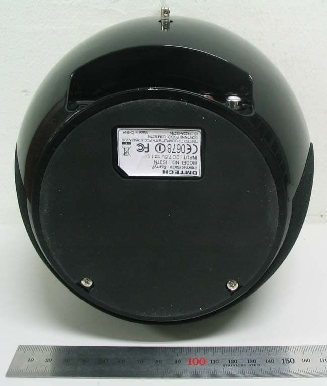
Q9MIS07N
Jan 30, 2008Internet Radio device
Equipment Class
DTS - Digital Transmission System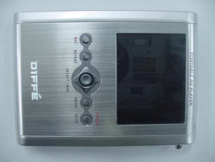
Q9MDM-AV7
Nov 25, 2004Portable Mulitmedia Player
Equipment Class
JBP - Part 15 Class B Computing Device Peripheral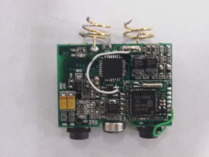
Q9MDM-FA60
Oct 28, 2004MP3 PLAYER
Equipment Class
JBP - Part 15 Class B Computing Device Peripheral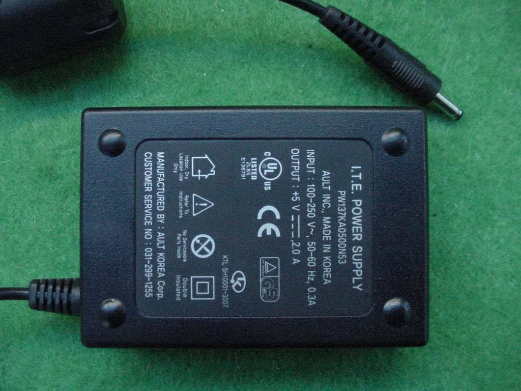
Q9MDM-AV10
Feb 23, 2004DIGITAL PRESENTATION DEVICE
Equipment Class
JBP - Part 15 Class B Computing Device Peripheral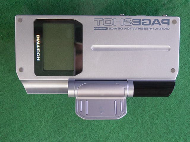
Q9MDM-P200
Jul 07, 2003DIGITAL PRESENTATION DEVICE
Equipment Class
JBP - Part 15 Class B Computing Device Peripheral