QA5-HAB-03002Wireless Access Bridge
SendFar Technology Co., Ltd.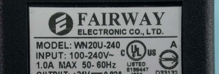
Click to zoom
Application Details
- Equipment Class
- DTS - Digital Transmission System
- Date of Grant
- Nov 20, 2003
- Application Purpose
- Original Equipment
- Date of Application
- Nov 20, 2003
- Equipment Note
- Wireless Access Bridge
- Frequency Range
- 2412.00000000 - 2462.00000000
- Company
- SendFar Technology Co., Ltd.
- Country
- Taiwan
Documents & Files
Document Text
Text extracted from the exhibit documents filed with the FCC. Open a document above to read the original.
Users Manual
SF-300CB 1/14 Copyright © 2002 SendFar Technology. All rights reserved. SendFar is the registered trademark of SendFar Technology Co., Ltd.. SF-300 IEEE 802.11b Wireless ACCESS Bridge Product Introduction August 1, 2003 Version 0.23 (The product specification is subject to change without notice.) SF-300CB 2/14 Copyright © 2002 SendFar Technology. All rights reserved. SendFar is the registered trademark of SendFar Technology Co., Ltd.. 1. Introduction This chapter describes the package contents, system requirements, features and benefits, applications and network configurations of SF-300 Wireless Access Bridge. 1.1 Package Contents The SF-300 package contains the following item as shown in Figure. 1. One (1) SF-300 Wireless Access Bridge 2. One (1) 5dBi Omni rubber antenna 3. One (1) 1m RJ-45 CAT 5 Ethernet cable 4. One (1) 1m RS-232 Console Port Cable 5. One (1) 24V, 0.83A AC/DC adapter with wall-plug power cord 6. One (1) Inline power (PoE) injector 7. One (1) User manual CD-disc 8. One (1) set of wall mounting screws 1.2 Product Descriptions The SF-300 Wireless Access Bridge is a fully interoperable with IEEE802.11b compliant product for wireless LAN system requires the use of this Wireless Access Bridge. The Wireless Access Bridge extends wireless networking capability to desktop PC, printer, scanner, medical equipment, manufacturing machinery, bar code data collection and other data collection device. It provides a reliable, cost-effective interface between device utilizing Ethernet ports and wireless LAN Access Point. The Wireless Access Bridge can move freely under the coverage area of the Access Point while remaining connected to the Ethernet network. 1.3 Product Features z High RF Output Power 19dBm (typical) z Power-over-Ethernet z User authentication in Web-based manager z MAC address based access control z Wireless 64-/128-bit WEP encryption z SNMP, SNMP MIB-II and proprietary MIBs (See the definition of the proprietary MIBs in Appendix A) 1.4 System Requirements Installation of the Wireless Access Bridge requires: 1. A Windows-based PC/AT compatible computer or Ethernet data device with an available RJ-45 Ethernet port to run the configuration program or with TCP/IP connection to the Ethernet network. 2. A 10/100Base-T Ethernet RJ-45 Ethernet cable is connected to Ethernet network. 3. A RS-232 Consol Port cable is connected to PC/AT compatible computer. 4. An AC power outlet (100~240V, 50~60Hz) supplies the power. 1.5 Features and Benefits FeaturesBenefits 11Mbps data rateHigh-speed data transmission SF-300CB 3/14 Copyright © 2002 SendFar Technology. All rights reserved. SendFar is the registered trademark of SendFar Technology Co., Ltd.. IEEE802.11b compliantFully interoperable with IEEE802.11b compliant products Output up to 100mWHigher power provides extended range Automatic data rate scaling at 11,5.5,2 and 1Mbps Optimized throughput, range and connectivity 64/128bits WEP data encryption/decryption Powerful data security Easy configurationFlexibly meet changing application requirements Wide temperature range and robust mechanical design Delivers reliable, top performance in the most demanding environments Power-over-EthernetEasy install and cost-effective Metal housingRobust facility for vertical market 1.6 Applications The SF-300 Wireless Access Bridge is easy to install and highly efficient. The following list describes some of the many applications made possible through the power and flexibility of wireless LANs: 1. Difficult-to-wire environments There are many situations where wires can not or not easily be laid. Historic buildings, older buildings, open areas and across busy streets make the installation of LANs either impossible or very expensive. 2. Temporary workgroups Consider situations in parks, athletic arenas, exhibitions, disaster-recovery, temporary office and construction sites where one wants a temporary WLAN established and removed. 3. The ability to access real-time information Doctors/nurses, point-of-sale employees, and warehouse workers can access real- time information while dealing with patients, serving customers and processing information. 4. Frequently changed environments Show rooms, meeting rooms, retail stores, and manufacturing sites where frequently rearrange the workplace. 5. Small Office and Home Office (SOHO) networks SOHO users need a cost-effective, easy and quick installation of a small network. 6. Wireless extensions to Ethernet networks Network managers in dynamic environments can minimize the overhead caused by moves, extensions to networks, and other changes with wireless LANs. 7. Wired LAN backup Network managers implement wireless LANs to provide backup for mission-critical applications running on wired networks. 8. Training/Educational Facilities Training sites at corporations and students at universities use wireless connectivity to ease access to information, information exchanges, and learning. 1.7 Infrastructure Modes Infrastructure mode connects the Wireless Access Bridge Ethernet port with PC or data device is which has standard Ethernet capabilities, and requires the use of a wireless Access Point. The Wireless Access Bridge associates with an Access Point SF-300CB 4/14 Copyright © 2002 SendFar Technology. All rights reserved. SendFar is the registered trademark of SendFar Technology Co., Ltd.. located nearby. The Access Point sees this Wireless Access Bridge network device combination as a standard Mobile Unit (MU). The AP forms a bridge between the wired LAN and the wireless clients. In infrastructure mode, the AP is a dedicated device that is wired into the LAN backbone while the Wireless Access Bridge units can be physically moved throughout the WLAN. The Wireless Access Bridge communicates with any device on the network by routing data through the associated AP. Multiple APs with the same ESSID can be placed within the same area. The 802.11b standard enables the Wireless Access Bridge to roam among the MUs and Acces…
Text truncated - open the document above for the full version.
Users Manual
SF-300CB 8/14 Copyright © 2002 SendFar Technology. All rights reserved. SendFar is the registered trademark of SendFar Technology Co., Ltd.. 5. Product Specifications 5.1 General Radio Data Rate11, 5.5, 2 and 1 Mbps, Auto Fall-Back Client Interface10/100Base-T Ethernet Range (open environment)300m @ 11.0Mbps 400m @ 05.5Mbps 500m @ 02.0Mbps 800m @ 01.0Mbps EMC CertificationsFCC Part 15 ETSI 300/328 CompatibilityFully interoperable with IEEE802.11b compliant products Power Supply AC/DC Adapter:24V / 0.83A (via AC power outlet 100~240V, 50~60Hz) PoE:16 ~ 32V 5.2 Network Information Network ArchitectureInfrastructure (via SendFar AP/RB-8110 AP or Bridge) DriversWindows 95/98/ME/2000/NT 4.0/XP Access ProtocolCSMA/CA RoamingIEEE802.11b compliant Security64-/128-bit data encryption 5.3 Radio Specifications Frequency Band2.4 – 2.4835 GHz Radio TypeDirect Sequence Spread Spectrum (DSSS) ModulationCCK (11, 5.5Mbps) DQPSK (2Mbps) DBPSK (1Mbps) Operation Channels North America:11 Japan:14 Europe:13 Spain:2 France:4 Available Transmit Power Settings<30dBm (<1W) For FCC <20dBm (<100mW) For CE AntennaOne detachable 5dBi omni-direction rubber antenna with RP-SMA (FCC) or SMA (ETSI) connector & 12dBi patch Antenna ( Option) Sensitivity @ FER=0.0811.0 Mbps < -85dBm 5.5 Mbps < -88dBm 02.0 Mbps < -91dBm 01.0 Mbps < -93dBm SF-300CB 9/14 Copyright © 2002 SendFar Technology. All rights reserved. SendFar is the registered trademark of SendFar Technology Co., Ltd.. 5.4 Environmental Temperature Range-20 to 55°C (operating) -20 to 75°C (storage) Humidity (non-condensing)5% to 95% typical 5.5 Physical Specifications Dimensions138.7mm x 104.0mm x 38.0mm Weight600g SF-300CB 10/14 Copyright © 2002 SendFar Technology. All rights reserved. SendFar is the registered trademark of SendFar Technology Co., Ltd.. 6. Software Specifications Protocol TCP/IP NAT/NAPT DHCP Client Virtual Server Mapping (NAT inbound server) 802.1d Transparent Bridging Security 64-/128-bit WEP encryption MAC address based access control User authentication in Web-based Manager Management Web-based Manager Telnet configuration Console (RS-232) configuration SNMP v1 SNMP MIB-II Private MIB Misc supports VLAN pass through Firmware upgrade TFTP (Trivial FTP) Xmodem, 1K Xmodem Zmodem SF-300CB 11/14 Copyright © 2002 SendFar Technology. All rights reserved. SendFar is the registered trademark of SendFar Technology Co., Ltd.. 7. Product Block Diagram [Blank] SF-300CB 12/14 Copyright © 2002 SendFar Technology. All rights reserved. SendFar is the registered trademark of SendFar Technology Co., Ltd.. 8. Regulatory Compliance Information FCC Part 15 Notice (Applicable to use within the USA) CAUTION: FCC Radio-Frequency Exposure Notice This device generates and radiates radio-frequency energy. In order to comply with FCC radio-frequency radiation exposure compliance requirements, a separation distance of at least 20 cm must be maintained between the antenna of the device and all persons. This product does not contain any user serviceable components. Any unauthorized product changes or modifications will invalidate SendFar’s warranty and all applicable regulatory certifications and approvals. This transmitter must not be co-located or operating in conjunction with any other antenna or transmitter. Unintentional Radiator WARNING: This equipment has been tested and found to comply with the limits for a Class B digital device as applicable, pursuant to Part 15 of the FCC Rules. These limits are designed to provide reasonable protection against harmful interference in a residential installation. This equipment generates, uses and can radiate radio frequency energy and, if not installed and used in accordance with the instructions, may cause harmful interference to radio communications. However, there is no guarantee that interference will not occur in a particular installation. If this equipment does cause harmful interference to radio or television reception, which can be determined by turning the equipment off and on, the user is encouraged to try to correct the interference by one or more of the following measures: Reorient or relocate the receiving antenna. Increase the separation between the equipment and receiver. Connect the equipment into an outlet on a circuit different from that to which the receiver is connected. Consult the dealer or an experienced radio/TV technician for help. This device complies with part 15 of the FCC Rules. Operation is subject to the following two conditions: 1 This device may not cause harmful interference, and (2) this device must accept any interference received, including interference that may cause undersired operation. 2 The user may find the following booklet prepared by the Federal Communications Commission helpful:The Interference Handbook This booklet is available from the U.S. Government Printing Office, Washington, D.C. 20402. Stock No. 004-000-00345-4. SF-300CB 13/14 Copyright © 2002 SendFar Technology. All rights reserved. SendFar is the registered trademark of SendFar Technology Co., Ltd.. Appendix A The purpose of this Appendix is to describe a SNMP proprietary MIB for the SendFar SF- 300 Wireless Access Bridge. This MIB Module defines SendFar implementation-specific metrics useful in managing IEEE 802.11 on SendFar boxes. This is to be used as a supplement to the standard 802.11 MIB proposed by IEEE. Information contained in the MIB elements defined in this module is affected by the Web configuration, except where it is explicitly noted to the contrary. Parameter Definition Table: NameSyntaxAccess Status Information ConnectedToSSIDOctet Stringread-only UsingChannelIntegerread-only AccessPointMACAddressOctet Stringread-only CurrentTransmissionRateIntegerread-only CurrentLinkQualityIntegerread-only ClientBridgeMACAddressOctet Stringread-only CurrentIPAddressIP Addressread-only LinkUpIndicatorIntegerread-only Firmware VersionOctet Stringread-only Counters ReceivedPacketsGoodCoun…
Text truncated - open the document above for the full version.
Cover Letter(s)
American Telecommunications Certification Body Inc. 6731 Whittier Ave, McLean, VA 22101 November 14, 2003 RE: FCC ID: QA5-HAB-03002 Attention: Ellis Wu I have a few comments on this Application. 1. The operational description states that two antennae are used with this transmitter. The description also states that reverse SMA are used on both antennae. Please note that while the end of the cable that goes to the PCMCIA card uses reverse SMA, the other end of the cable which connects to the patch antenna itself appears to be a different type. Please verify that this is a non-standard antenna connector. x 2. Please note that the manual (page 8) states only one 5dBi antenna is used with the device. The operational description and the photos show two antennae and the MPE is calculated using a 12dBi antenna. Please reconcile the manual, MPE and operational description antenna statements. ok 3. Please note that the manual says the device can be used in other than the US. While the manual says 11 channels are useable in the US, there is nothing that indicates that the device cannot be made to operate on non-US channels for US devices. Please provide evidence that the user of the device cannot make the device, by either software or other, operate on any non-US frequency. This may be done by attesting to this fact. 4. Please verify that the length of antenna wire used in radiated testing is the actual length of antenna wire that will be provided with the transmitter. x 5. FYI – no action needed. Please note that the reduction in power for antennae over 6dBi applies to a conducted power level of 30dBm. This means that reduction in power does not have to occur until the 36dB point. Since your device is only 20dBm the reduction does not have to occur until a 16dBi antenna is used. No reduction in power is needed if only a 12dBi antenna is used. Dennis Ward mailto:[email protected] The items indicated above must be submitted before processing can continue on the above referenced application. Failure to provide the requested information may result in application termination. Correspondence should be considered part of the permanent submission and may be viewed from the Internet after a Grant of Equipment Authorization is issued. Please do not respond to this correspondence using the email reply button. In order for your response to be processed expeditiously, you must submit your documents through the AmericanTCB.com website. Also, please note that partial responses increase processing time and should not be submitted. Any questions about the content of this correspondence should be directed to the sender.
Cover Letter(s)
-----Original Message----- From: [email protected] [mailto:[email protected]] Sent: Friday, November 21, 2003 6:05 PM To: dward Cc: [email protected] Subject: 回信: RE: QA5-HAB-03002 Dennis, After confirm with my client, the firmware be wrote to flash, for the channel selection by end user is impossible. Thanks Best Regards. 吳佳鑫 / Ellis Wu E-mail : [email protected] 誠信科技 / ADT Corp. TEL : +886 3 3270910 #1624 FAX : +886 3 3270892 "dward" <[email protected]> 收件人 2003/11/22 上午 <[email protected]> 01:53 副本抄送 <[email protected]> 主旨 RE: QA5-HAB-03002 HI Stephanie I got the revised external photos showing reverse connectors. This answers the cable question and the cable length question. The only outstanding item is the verification that the user cannot make this device operate on any non-US channels by use of software or any other means. Once I get this, I can issue the grant. Thanks Dennis
External Photos
Page 1 CONSTRUCTION PHOTOS OF EUT Page 2 Page 3 Page 4 Page 5
External Photos
Page 7 Page 8 Page 9 Page 10 Page 11
External Photos
Page 22 Page 23 Page 24 Page 25 Page 26 Page 27 Page 28 Page 29
External Photos
Page 1 CONSTRUCTION PHOTOS OF EUT Page 2 Page 3 Page 4
ID Label/Location Info
2 mm 2 mm FOR HOME OR OFFICE USE FCC ID: QA5-HAB-03002 Tested To Comply With FCC Standards 0560 Model No.: SF-300 AC: 100~240V 50~60Hz DC: 24V / 0.83A MADE IN TAIWAN 90 mm 45 mm S/N: This device complies with Part 15 of the FCC Rules. Operation is subject to the following two conditions:(1)This device may not cause harmful interference, and (2)this device must accept any interference received, including interference that may cause undesired operation. (SF-300) 2 mm 2 mm 90 mm 45 mm (SF-300) SF-300 LABEL LOCATION Label Location This device complies with Part 15 of the FCC Rules. Operation is subject to the following two conditions:(1)This device may not cause harmful interference, and (2)this device must accept any interference received, including interference that may cause undesired operation. FOR HOME OR OFFICE USE Tested To Comply With FCC Standards FCC ID: QA5-HAB-03002 MADE IN TAIWAN 0560 Model No.: SF-300 AC: 100~240V 50~60Hz DC: 24V/0.83A S/N:
Internal Photos
Page 6 Page 7
Internal Photos
Page 12 Page 13 Page 14 Page 15 Page 16 Page 17 Page 18 Page 19 Page 20 Page 21
Operational Description
FCC ID: QA5-HAB-03002 Report No.RF921017R01 Operational Description The transmitter of the EUT is powered by POE (Power over Ethernet) and connected with managing computer through RJ45 port. The antennas used in this product are Dipole antenna and Patch antenna. The antenna connector is Reversed SMA. Under normal use condition, the user has to keep at least 20cm separation distance between radiator and the body of the user. The other instruction, please have a look at the users manual. DSSS Information This device is Direct Sequence Spread Spectrum, the data is mixed by pseudorandom code which is an orthogonal code. The mixed data is digital modulated by BPSK and QPSK technique depends on the data rates. The CCK coding is applied for increasing the data rate, and also the processing gain will be increased. The bit rates are 1,2,5.5,11Mbps, the symbol rates are 1,1,1.375,1.375Mbps, the chip rates are always 11Mbps. So, the Chip/symbol is 11,11,8 and 8 respectively. Although is higher bit rate, the processing gain is lower than 10, but the CCK coding used in higher bit rate will provide 2.2dB coding gain.
RF Exposure Info
FCC ID: QA5-HAB-03002 Report No: RF921017R01 1 RF EXPOSURE REPORT REPORT NO.: RF921017R01 MODEL NO.: SF-300 ACCORDING: FCC Guidelines for Human Exposure IEEE C95.1 APPLICANT: SendFar Technology Co., Ltd. ADDRESS: 15FL., NO.866-2, JUNGJENG RD., JUNGHE CITY, TAIPEI, TAIWAN 235, R.O.C. ISSUED BY: Advance Data Technology Corporation LAB LOCATION: 47 14th Lin, Chiapau Tsun, Linko, Taipei, Taiwan, R.O.C. FCC ID: QA5-HAB-03002 Report No: RF921017R01 2 RF Exposure Measurement (Mobile Device) 1. Introduction In this document, we try to prove the safety of radiation harmfulness to the human body for our product. The limit for Maximum Permissible Exposure (MPE) specified in FCC 1.1310 is followed. The Gain of the antenna used in this product is measured in a Fully Anechoic Chamber (FAC) calibrated for antenna measurement in ADT, and also the maximum total power input to the antenna is measured. Through the Friis transmission formula and the maximum gain of the antenna, we can calculate the distance, away from the product, where the limit of MPE is reached. Although the Friis transmission formula is a far field assumption, the calculated result of that is an over-prediction for near field power density. We will take that as the worst case to specify the safety range. 2. RF Exposure Limit According to FCC 1.1310: The criteria listed in the following table shall be used to evaluate the environmental impact of human exposure to radio-frequency (RF) radiation as specified in 1.1307(b) LIMITS FOR MAXIMUM PERMISSIBLE EXPOSURE (MPE) Frequency Range (MHz) Electric Field Strength (V/m) Magnetic Field Strength (A/m) Power Density (mW/cm 2 ) Average Time (minutes) (A)Limits For Occupational / Control Exposures 300-1500......F/3006 1500-100,000......56 (B)Limits For General Population / Uncontrolled Exposure 300-1500......F/15006 1500-100,000......1.030 F = Frequency in MHz FCC ID: QA5-HAB-03002 Report No: RF921017R01 3 3. Friis Formula Friis transmission formula : Pd = (Pout*G) / (4*pi*r 2 ) where Pd = power density in mW/cm 2 Pout = output power to antenna in mW G = gain of antenna in linear scale Pi = 3.1416 R = distance between observation point and center of the radiator in cm If we know the maximum Gain of the antenna and the total power input to the antenna, through the calculation, we will know the MPE value at distance r. Ref. : David K. Cheng, Field and Wave Electromagnetics, Second Edition, Page 640, Eq. (11-133). 4 EUT Operating condition The software provided by Manufacturer enabled the EUT to transmit and receive data at lowest, middle and highest channel individually. 5. Classification The antenna of this product, under normal use condition, is at least 20cm away from the body of the user. Warning statement to the user for keeping at least 20cm or more separation distance with the antenna should be included in users manual. So, this device is classified as Mobile Device. FCC ID: QA5-HAB-03002 Report No: RF921017R01 4 6 Test Results 6.1 Antenna Gain The maximum Gain measured in Fully Anechoic Chamber is 12dBi or 15.85 (numeric). 6.2 Output Power Into Antenna & RF Exposure value at distance 20cm: Channel Channel Frequency (MHz) Output Power to Antenna (mW) Power Density (mW/cm 2 ) Limit of Power Density (mW/cm 2 ) 12412100.000.3151.0 62437100.000.3151.0 112462100.000.3151.0
Test Report
FCC ID: QA5-HAB-03002 Report No.: RF921017R011Issued: November 6, 2003 FCC TEST REPORT REPORT NO.: RF921017R01 MODEL NO.: SF-300 RECEIVED: Oct. 15, 2003 TESTED: Oct. 15 ~ Nov. 5, 2003 APPLICANT: SendFar Technology Co., Ltd. ADDRESS: 15FL., NO.866-2, JUNGJENG RD., JUNGHE CITY, TAIPEI, TAIWAN 235, R.O.C. ISSUED BY: Advance Data Technology Corporation LAB LOCATION: 47 14th Lin, Chiapau Tsun, Linko, Taipei, Taiwan, R.O.C. This test report consists of 58 pages in total. It may be duplicated completely for legal use with the approval of the applicant. It should not be reproduced except in full, without the written approval of our laboratory. The client should not use it to claim product endorsement by CNLA, NVLAP or any government agencies. The test results in the report only apply to the tested sample. 0528 ILAC MRA Lab Code: 200102-0 FCC ID: QA5-HAB-03002 Report No.: RF921017R012Issued: November 6, 2003 Table of Contents 1CERTIFICATION .................................................................................................................... 4 2SUMMARY OF TEST RESULTS ........................................................................................... 5 3GENERAL INFORMATION .................................................................................................... 6 3.1 GENERAL DESCRIPTION OF EUT ...................................................................................... 6 3.2 DESCRIPTION OF TEST MODES ........................................................................................ 7 3.3 GENERAL DESCRIPTION OF APPLIED STANDARDS ....................................................... 7 3.4 DESCRIPTION OF SUPPORT UNITS .................................................................................. 8 3.5 CONFIGURATION OF SYSTEM UNDER TEST ................................................................... 9 4TEST TYPES AND RESULTS.............................................................................................. 10 4.1 CONDUCTED EMISSION MEASUREMENT ...................................................................... 10 4.1.1LIMITS OF CONDUCTED EMISSION MEASUREMENT.................................................... 10 4.1.2TEST INSTRUMENTS ......................................................................................................... 10 4.1.3TEST PROCEDURES.......................................................................................................... 11 4.1.4DEVIATION FROM TEST STANDARD................................................................................ 11 4.1.5TEST SETUP ....................................................................................................................... 12 4.1.6EUT OPERATING CONDITIONS ........................................................................................ 12 4.1.7TEST RESULTS ................................................................................................................... 13 4.2 RADIATED EMISSION MEASUREMENT............................................................................ 19 4.2.1 LIMITS OF RADIATED EMISSION MEASUREMENT........................................................ 19 4.2.2TEST INSTRUMENTS ......................................................................................................... 20 4.2.3TEST PROCEDURES.......................................................................................................... 21 4.2.4DEVIATION FROM TEST STANDARD................................................................................ 21 4.2.5TEST SETUP ....................................................................................................................... 22 4.2.6EUT OPERATING CONDITIONS ........................................................................................ 22 4.2.7TEST RESULTS (A) ............................................................................................................. 23 4.2.8TEST RESULTS (B) ............................................................................................................. 28 4.3 6dB BANDWIDTH MEASUREMENT ................................................................................... 33 4.3.1 LIMITS OF 6dB BANDWIDTH MEASUREMENT ................................................................ 33 4.3.2TEST INSTRUMENTS ......................................................................................................... 33 4.3.3TEST PROCEDURE ............................................................................................................33 4.3.4DEVIATION FROM TEST STANDARD................................................................................ 33 4.3.5TEST SETUP ....................................................................................................................... 34 FCC ID: QA5-HAB-03002 Report No.: RF921017R013Issued: November 6, 2003 4.3.6EUT OPERATING CONDITIONS ........................................................................................ 34 4.3.7TEST RESULTS ................................................................................................................... 35 4.4MAXIMUM PEAK OUTPUT POWER................................................................................... 39 4.4.1LIMITS OF MAXIMUM PEAK OUTPUT POWER MEASUREMENT ................................... 39 4.4.2TEST INSTRUMENTS ......................................................................................................... 39 4.4.3TEST PROCEDURES.......................................................................................................... 40 4.4.4DEVIATION FROM TEST STANDARD................................................................................ 40 4.4.5TEST SETUP ....................................................................................................................... 40 4.4.6EUT OPERATING CONDITIONS ..........................................................…
Text truncated - open the document above for the full version.
Test Setup Photos
FCC ID: QA5-HAB-03002 Report No.: RF921017R011Issued: November 6, 2003 FCC TEST REPORT REPORT NO.: RF921017R01 MODEL NO.: SF-300 RECEIVED: Oct. 15, 2003 TESTED: Oct. 15 ~ Nov. 5, 2003 APPLICANT: SendFar Technology Co., Ltd. ADDRESS: 15FL., NO.866-2, JUNGJENG RD., JUNGHE CITY, TAIPEI, TAIWAN 235, R.O.C. ISSUED BY: Advance Data Technology Corporation LAB LOCATION: 47 14th Lin, Chiapau Tsun, Linko, Taipei, Taiwan, R.O.C. This test report consists of 58 pages in total. It may be duplicated completely for legal use with the approval of the applicant. It should not be reproduced except in full, without the written approval of our laboratory. The client should not use it to claim product endorsement by CNLA, NVLAP or any government agencies. The test results in the report only apply to the tested sample. 0528 ILAC MRA Lab Code: 200102-0 FCC ID: QA5-HAB-03002 Report No.: RF921017R012Issued: November 6, 2003 Table of Contents 1CERTIFICATION .................................................................................................................... 4 2SUMMARY OF TEST RESULTS ........................................................................................... 5 3GENERAL INFORMATION .................................................................................................... 6 3.1 GENERAL DESCRIPTION OF EUT ...................................................................................... 6 3.2 DESCRIPTION OF TEST MODES ........................................................................................ 7 3.3 GENERAL DESCRIPTION OF APPLIED STANDARDS ....................................................... 7 3.4 DESCRIPTION OF SUPPORT UNITS .................................................................................. 8 3.5 CONFIGURATION OF SYSTEM UNDER TEST ................................................................... 9 4TEST TYPES AND RESULTS.............................................................................................. 10 4.1 CONDUCTED EMISSION MEASUREMENT ...................................................................... 10 4.1.1LIMITS OF CONDUCTED EMISSION MEASUREMENT.................................................... 10 4.1.2TEST INSTRUMENTS ......................................................................................................... 10 4.1.3TEST PROCEDURES.......................................................................................................... 11 4.1.4DEVIATION FROM TEST STANDARD................................................................................ 11 4.1.5TEST SETUP ....................................................................................................................... 12 4.1.6EUT OPERATING COND…
Text truncated - open the document above for the full version.
Contact Information
Applicant
Yuan Chung Wu(Vice President)
Technical Contact
Advance Data Technology CorporationEllis Wu
[email protected]886-3-327-0910
13-1, Lane19, WenShan 3rd ., St., · Taoyuan · Taiwan
Test Firm
Advanced Compliance Solutions, Inc.Sam Wismer
Technical Specifications
| # | Rule Parts | Frequency Range | Power Output |
|---|---|---|---|
| 1 | 15C | 2.41 GHz - 2.46 GHz | 100.00 mW |
Other Applications from SendFar Technology Co., Ltd.

QA5-OAB-04004
Jul 15, 2004Wireless Access Bridge
Equipment Class
DTS - Digital Transmission System
QA5-ORB-04002
Jul 11, 2004Wireless Router Bridge
Equipment Class
DTS - Digital Transmission System
QA5-OAP-04003
Jul 04, 2004Wireless Access Point
Equipment Class
DTS - Digital Transmission System
QA5-MPI-04001
Jun 02, 2004Wireless LAN Card
Equipment Class
DTS - Digital Transmission System
QA5-OAB-03001
Nov 17, 2003Wireless Access Bridge
Equipment Class
DTS - Digital Transmission System