QFXNHL-8Nokia 3650 mobile phone
Microsoft Corporation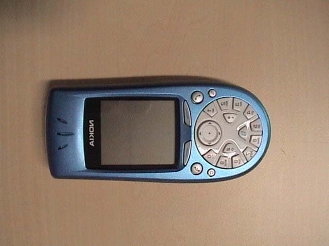
Click to zoom
Application Details
- Equipment Class
- PCE - PCS Licensed Transmitter held to ear
- Date of Grant
- Dec 25, 2002
- Application Purpose
- Original Equipment
- Date of Application
- Dec 25, 2002
- Equipment Note
- Nokia 3650 mobile phone
- Frequency Range
- 1850.20000000 - 1909.80000000
- Company
- Microsoft Corporation
- Country
- United States
Documents & Files
Document Text
Text extracted from the exhibit documents filed with the FCC. Open a document above to read the original.
Users Manual
Nokia 3650 User Guide FCC DRAFT The wireless phone described in this guide is approved for use in GSM 900, GSM 1800, and GSM 1900 networks. LEGAL INFORMATION Part No. 9355722, Issue No. 1 1 1 Copyright ©2002 Nokia. All rights reserved. Nokia, Nokia Connecting People, Nokia 3650, and the Nokia Original Accessories logos are trademarks or registered trademarks of Nokia Corporation. All other product and company names mentioned herein may be trademarks or tradenames of their respective owners. Printed in Canada November/2002 US Patent No 5818437 and other pending patents. T9 text input software Copyright ©1999-2002. Tegic Communications, Inc. All rights reserved. Includes RSA BSAFE cryptographic or security protocol software from RSA Security. Java is a trademark of Sun Microsystems, Inc. The information in this user guide was written for the Nokia 3650 phone. Nokia operates a policy of ongoing development. Nokia reserves the right to make changes and improvements to any of the products described in this document without prior notice. UNDER NO CIRCUMSTANCES SHALL NOKIA BE RESPONSIBLE FOR ANY LOSS OF DATA OR INCOME OR ANY SPECIAL, INCIDENTAL, AND CONSEQUENTIAL OR INDIRECT DAMAGES HOWSOEVER CAUSED. THE CONTENTS OF THIS DOCUMENT ARE PROVIDED “AS IS.” EXCEPT AS REQUIRED BY APPLICABLE LAW, NO WARRANTIES OF ANY KIND, EITHER EXPRESS OR IMPLIED, INCLUDING, BUT NOT LIMITED TO, THE IMPLIED WARRANTIES OF MERCHANTABILITY AND FITNESS FOR A PARTICULAR PURPOSE, ARE MADE IN RELATION TO THE ACCURACY AND RELIABILITY OR CONTENTS OF THIS DOCUMENT. NOKIA RESERVES THE RIGHT TO REVISE THIS DOCUMENT OR WITHDRAW IT AT ANY TIME WITHOUT PRIOR NOTICE. EXPORT CONTROLS This product contains commodities, technology or software exported from the United States in accordance with the Export Administration regulations. Diversion contrary to U.S. law is prohibited. FCC/INDUSTRY CANADA NOTICE Your phone may cause TV or radio interference (for example, when using a telephone in close proximity to receiving equipment). The FCC or Industry Canada can require you to stop using your telephone if such interference cannot be eliminated. If you require assistance, contact your local service facility. This device complies with part 15 of the FCC rules. This device contains a radio transceiver and digital circuitry that supports its features. Operation of the digital device circuitry is subject to the following two conditions: (1) this device may not cause harmful interference, and (2) this device must accept any interference received, including interference that may cause undesired operation. Modifications to this device not authorized by Nokia may void the authority granted for operation of this device and should not be made. [ iii ] Contents General information 11 Register your phone 11 Understand your phone 11 Menu 20 Options lists 21 Navigation bar - moving horizontally 22 Actions common to all applications 22 Volume control 24 Your phone 27 Make a call 27 Answer a call 30 Log - Call log and general log 33 SIM folder 38 Settings 39 Change general settings 39 Phone settings 39 Call settings 41 Connection settings 43 Date and time 50 Security 50 Call restriction (network service) 55 Network 56 Accessory settings 56 Contacts 59 Create contact cards 59 Copy contacts between the SIM card and phone memory 59 Edit contact cards 60 Options when viewing a contact card 61 Manage contact groups 65 [ iv ] Camera and Images 67 Take pictures 67 Images - Store pictures 71 Record a video clip 77 Watch a video clip 78 RealOne Player™ 79 Playing media files 79 Sending media files 81 Changing the settings 81 Messaging 83 Messaging - General information 84 Write text 86 Create and send new messages 90 Inbox - receive messages 97 My folders 102 Remote mailbox 102 Outbox 107 View messages on a SIM card 108 Cell broadcast (network service) 108 Service command editor 109 Messaging settings 109 Wireless village 115 Profiles 117 Change the profile 117 Customize profiles 117 Favorites 119 Add shortcuts 119 [ v ] Calendar and To-do 121 Create calendar entries 121 Set calendar alarms 124 Send calendar entries 125 To-do 125 Extras 127 Calculator 127 Composer 128 Converter 129 Notes 131 Clock 131 Recorder 132 Memory card 133 Basic steps for accessing 137 Setting up the phone for the browser service 138 Browsing 140 Viewing saved pages 142 Downloading 143 Ending a connection 144 Browser settings 144 Applications (Java™) 147 Installing a Java application 148 Java application settings 149 Manager - installing applications and software 151 Connectivity 155 Bluetooth connection 155 Infrared connection 161 Connect your phone to a computer 162 Use your phone as a modem to connect to the Internet or to send or receive faxes 163 [ vi ] PC Suite for Nokia 3650 165 Software and hardware requirements 165 Installing PC Suite 166 Connecting your phone to the PC 167 Starting to use PC Suite 169 Online and offline modes 170 Connection status 171 Main window information 172 PC Suite applications 173 Removing PC Suite from your PC 175 Reference information 177 Battery statements 177 Use proper care and maintenance 178 Understand Important safety information 179 Use Accessories safely 184 accessories 185 Glossary 189 Technical information 191 Troubleshooting 191 Frequently Asked questions (faq) 193 A Guide to Safe and Responsible Wireless Phone Use 204 Consumer Update on Wireless Phones 208 [ 7 ] For your safety Read these simple guidelines. Breaking the rules may be dangerous or illegal. Further detailed information is given in this User guide. Do not switch the phone on when wireless phone use is prohibited or when it may cause interference or danger. ROAD SAFETY COMES FIRST Don't use a hand-held phone while driving. INTERFERENCE All wireless phones may get interference, which could affect performance. SWITCH OFF IN HOSPITALS Follow any regulations or rules. Switch the phone off near medical equipment. SWITCH OFF IN AIRCRAFT Wireless devices can cause interference in aircraft. S…
Text truncated - open the document above for the full version.
Cover Letter(s)
American Telecommunications Certification Body Inc. 6731 Whittier Ave, McLean, VA 22101 December 19, 2002 RE: FCC ID: QFXNHL-8 Attention: Andrew White I have a few comments on this Application. 1 The internal photos on pages 8, 9, 16, 18, 19 and 20 of the internal photos document Confidential_Exhibit 09 Internal Photo update.pdf are not clear. Please provide clear pictures of the circuitry under the shielding and the other photos indicated on the pages mentioned above. 2 Please note that 15.21 Information to the user, requires that the non-modification statement clearly inform the user that unauthorized modifications may void the users right to use the equipment. Please note that the statement on page 178 merely states that it may violate FCC regulations. This is not the intent of the statement. The intent as mentioned above is to inform the user that unauthorized modifications may void the user right to use the equipment. Please make this condition clear in the manual. 3 Please note that the accessories used to test SAR are not listed in the manual. Please list the approved accessories used during SAR testing (Battery, Type: BL-5C, DUT#232026 & #232027, Headset Type: HDE-2 DUT#232025) in the manual. 4 Please note that the technical information listed on page 188 of the manual does not provided the numbers referred to. Please provide a manual with the values indicated (i.e. putput power etc). 5 Please note the this is a part 15 device and as such must have the 2-condition statement required by 15.19 labeling requirements. This statement is to be on a label on the device unless size or justifiable reasons prevent the label from being placed on the device. If the label cannot be placed on the device due to size, etc. then the verbatim 2-condition statement MUST be placed in the instruction manual, pamphlet or on the box. Please provide the sample label to be placed on the device or alternately, please revise the manual to include the 2-condition statement or show proof that it will be on the box. 6 Please note that on pages 22 and 24 of the report you state that the maximum EIRP measured on channel 512 was 31.88dBm. On page 6 of the report you state that the maximum EIRP is 30.11dBm. Please note that reports are to report the MAXIMUM POWER levels during testing. These numbers do not agree. Please correct the report to give the maximum power levels measured. 7 The report indicates a higher power than measured in the SAR report (i.e. 31.88dBm in the EMC and 30.11dBm in the SAR). Please note that while for EIRP there may be justification for greater than 5% differences in power, under no circumstance is the SAR maximum power to be lower than that reported and measured in the EMC report. Please explain and if necessary retest the device so SAR levels are higher than those in the EMC report. 8 Please note that the SAR report states that EIRP measurements were not performed at the time SAR testing was done but at RFI in England. Please note it is not possible to determine if the device was actually outputting the maximum power at the time of test unless it was verified at the time of test. Please also note that IEEE1528 states that the power is to be adjusted to the maximum power the user will be subject to and that the power should be verified and steps should be taken to check on any variations of power DURING SAR testing. Please explain why EIRP measurements were not done at the time of SAR testing. Please provide evidence that the EIRP levels indicated in the report were indeed those verified during SAR testing. 9 Please note that the EMC report does not indicate that GPRS mode was tested. Please verify. z Page 2 December 19, 2002 Dennis Ward mailto:[email protected] The items indicated above must be submitted before processing can continue on the above referenced application. Failure to provide the requested information may result in application termination. Correspondence should be considered part of the permanent submission and may be viewed from the Internet after a Grant of Equipment Authorization is issued. Please do not respond to this correspondence using the email reply button. In order for your response to be processed expeditiously, you must submit your documents through the AmericanTCB.com website. Also, please note that partial responses increase processing time and should not be submitted. Any questions about the content of this correspondence should be directed to the sender.
Cover Letter(s)
7 th February 2003 Response to FCC Request for Additional Information on QFXNHL-8 1) Block diagram referenced in Request for Confidentiality letter See “exhibit 04 bt block diag question 1.pdf” and “exhibit 04 rf block diag question 1.pdf” 2) Confirmation that schematics provided are complete Schematics provided are RF and BT sheets only. Complete schematic to be kept confidential is attached below: See “Confidential schematics all question 2.pdf” 3) Confirmation of transmit frequency range stated on Form 731. Device is not expected to comply with band edge attenuation requirements if tuned to 1909.9 MHZ. Please correct as appropriate. The transmit frequency range is confirmed as 1850.2 – 1909.8 MHz, as stated on Form 731. Dennis Ward (ATCB) has agreed to update grant. 4) Confirmation that radiated power measurements were made for each SAR scan. Reported results appear to be identical to EMC reported values. Please provide full details including photographs of radiated power test used during SAR testing. If radiated testing was not performed during SAR testing please retest. Please provide answers to TCB query on this subject. There is no external connector available on QFXNHL-8 and therefore all power measurements are done radiated. Since SAR laboratories do not have the possibility to perform radiated EMC measurements by themselves, a separate EMC laboratory has to be used for this purpose. The same sample was used both in SAR and EMC measurements, and the sample was not modified between measurements. The TX power control loop of the QFXNHL-8 sample was used with the same power settings in both EMC and SAR measurements. Maximum power level was chosen for the measurements. Measured results are therefore valid and true to our best capability. Answer to TCB queries 6 to 8 was provided in corrected EMC report. (Confidential_Exhibit 06 Part 15_24 EMC report.pdf 12/30/2002 7:05:03 AM) 5) Please clarify if the composite BT transmitter was activated during SAR testing. Please provide SAR results for primary signal in worst case head and body configuration with and without BT transmitter turned on. The highest SAR result test cases have been re-measured (31 st January 2003) with BT activated: Ch. 518: Touch, left hand 0,550 W/kg From original SAR report Ch. 518: Touch, left hand + BT 0,484 W/kg Re-measured with BT activated Ch. 518: Body 0.415 W/kg From original SAR report (0.830 W/kg in GPRS mode) Ch. 518: Body 0.404 W/kg Re-measured with BT activated (0.808 W/kg in GPRS mode) The distributions of the re-measured SAR plots are very similar to the original SAR plots measured without BT. The lower SAR results from the re- measurements are partly due to differences in liquid parameters. As the validation results were lower in re-measurements it is logical that the SAR results from actual measurements are lower, too. 1880 MHz Liquid Parameters Conductivity Permittivity Head 22-08-2002 1.46 38.3 Head 31-01-2003 1.42 38.6 Body 03-09-2002 1.57 50.9 Body 31-01-2003 1.53 50.9 - - - - - - - - - - - - - - - - - - - - - - - - - - - - - - - - - - - - - - - - - - - - 1800 MHz Validation result Head 22-08-2002 39.64 W/kg Head 31-01-2003 37.12 W/kg Body 03-09-2002 39.96 W/kg Body 31-01-2003 39.48 W/kg - - - - - - - - - - - - - - - - - - - - - - - - - - - - - - - - - - - - - - - - - - - - Validation plots, actual SAR plots and z-axis scans from the re-measurements are attached below. See “Remeasurement results1 qest 5.pdf” 6) Descriptive information demonstrating compliance with part 15 frequency hopping control rules per 15.247 a). Specifically, how is the psuedorandom nature of the hop sequence established. How is equal use of all channels determined. How does the receiver tune sequence synchronize with the transmitter. Please state the hopping sequence. Please state the receiver BW. The equipment incorporates a compliant Bluetooth module. The frequency hopping control rules are explained in Chapter 11 of the Bluetooth Baseband Specification, which deals specifically with the hop selection algorithm. Please refer to the attached: See “Embedded File question 6 FCC 6676.pdf” The receiver bandwidth is 1MHz. 7) Photograph showing the BT antenna inside the device. The grant comment suggests that users can install the antenna. Please provide details of this. Update grant comment accordingly. Additionally, please add words to the effect that limit the use of this transmitter to the host device and configuration contained in this filing. The Bluetooth antenna is an integral part of the Printed Wiring Board and cannot, in normal use be accessed by the user. The photograph below shows the antenna. Dennis Ward (ATCB) has agreed to review the grant comment. The transmitter use and configuration is described in the user guide. 8) Justification for not maximizing spurious radiated emission by moving the receive antenna 1-4 m above 1 GHz frequency as stated in your measurement procedure. Please retest as appropriate. The test antenna used for measurements above 1GHz is a narrow beam horn antenna. Adjustment in the vertical plane results in the EUT falling outside of the capture range of the antennas beam. This results in loss of received signal for variations in height by more than a couple of inches. Test have been performed here at RFI over the years to prove this to be the case. We also perform a height search prior to the spurious test Bluetooth Antenna in order to determine the optimal height for the EUT. Once the height has been attained, no further height search for the horn is performed. 9) Radiated emissions procedure states that substitution method was used. Please clarify how this was performed. The test setup diagram does not suggest substitution method. Substitution method is not appropriate for Part 15 device. Retest as appropriate. Also, please detail how the levels in the plots were scaled relative to the limit. a) Please clarify how this was performed. A test reference antenna is set up on a test site and …
Text truncated - open the document above for the full version.
Cover Letter(s)
7 th February 2003 Response to FCC Request for Additional Information on QFXNHL-8 1) Block diagram referenced in Request for Confidentiality letter See “exhibit 04 bt block diag question 1.pdf” and “exhibit 04 rf block diag question 1.pdf” 2) Confirmation that schematics provided are complete Schematics provided are RF and BT sheets only. Complete schematic to be kept confidential is attached below: See “Confidential schematics all question 2.pdf” 3) Confirmation of transmit frequency range stated on Form 731. Device is not expected to comply with band edge attenuation requirements if tuned to 1909.9 MHZ. Please correct as appropriate. The transmit frequency range is confirmed as 1850.2 – 1909.8 MHz, as stated on Form 731. Dennis Ward (ATCB) has agreed to update grant. 4) Confirmation that radiated power measurements were made for each SAR scan. Reported results appear to be identical to EMC reported values. Please provide full details including photographs of radiated power test used during SAR testing. If radiated testing was not performed during SAR testing please retest. Please provide answers to TCB query on this subject. There is no external connector available on QFXNHL-8 and therefore all power measurements are done radiated. Since SAR laboratories do not have the possibility to perform radiated EMC measurements by themselves, a separate EMC laboratory has to be used for this purpose. The same sample was used both in SAR and EMC measurements, and the sample was not modified between measurements. The TX power control loop of the QFXNHL-8 sample was used with the same power settings in both EMC and SAR measurements. Maximum power level was chosen for the measurements. Measured results are therefore valid and true to our best capability. Answer to TCB queries 6 to 8 was provided in corrected EMC report. (Confidential_Exhibit 06 Part 15_24 EMC report.pdf 12/30/2002 7:05:03 AM) 5) Please clarify if the composite BT transmitter was activated during SAR testing. Please provide SAR results for primary signal in worst case head and body configuration with and without BT transmitter turned on. The highest SAR result test cases have been re-measured (31 st January 2003) with BT activated: Ch. 518: Touch, left hand 0,550 W/kg From original SAR report Ch. 518: Touch, left hand + BT 0,484 W/kg Re-measured with BT activated Ch. 518: Body 0.415 W/kg From original SAR report (0.830 W/kg in GPRS mode) Ch. 518: Body 0.404 W/kg Re-measured with BT activated (0.808 W/kg in GPRS mode) The distributions of the re-measured SAR plots are very similar to the original SAR plots measured without BT. The lower SAR results from the re- measurements are partly due to differences in liquid parameters. As the validation results were lower in re-measurements it is logical that the SAR results from actual measurements are lower, too. 1880 MHz Liquid Parameters Conductivity Permittivity Head 22-08-2002 1.46 38.3 Head 31-01-2003 1.42 38.6 Body 03-09-2002 1.57 50.9 Body 31-01-2003 1.53 50.9 - - - - - - - - - - - - - - - - - - - - - - - - - - - - - - - - - - - - - - - - - - - - 1800 MHz Validation result Head 22-08-2002 39.64 W/kg Head 31-01-2003 37.12 W/kg Body 03-09-2002 39.96 W/kg Body 31-01-2003 39.48 W/kg - - - - - - - - - - - - - - - - - - - - - - - - - - - - - - - - - - - - - - - - - - - - Validation plots, actual SAR plots and z-axis scans from the re-measurements are attached below. See “Remeasurement results1 qest 5.pdf” 6) Descriptive information demonstrating compliance with part 15 frequency hopping control rules per 15.247 a). Specifically, how is the psuedorandom nature of the hop sequence established. How is equal use of all channels determined. How does the receiver tune sequence synchronize with the transmitter. Please state the hopping sequence. Please state the receiver BW. The equipment incorporates a compliant Bluetooth module. The frequency hopping control rules are explained in Chapter 11 of the Bluetooth Baseband Specification, which deals specifically with the hop selection algorithm. Please refer to the attached: See “Embedded File question 6 FCC 6676.pdf” The receiver bandwidth is 1MHz. 7) Photograph showing the BT antenna inside the device. The grant comment suggests that users can install the antenna. Please provide details of this. Update grant comment accordingly. Additionally, please add words to the effect that limit the use of this transmitter to the host device and configuration contained in this filing. The Bluetooth antenna is an integral part of the Printed Wiring Board and cannot, in normal use be accessed by the user. The photograph below shows the antenna. Dennis Ward (ATCB) has agreed to review the grant comment. The transmitter use and configuration is described in the user guide. 8) Justification for not maximizing spurious radiated emission by moving the receive antenna 1-4 m above 1 GHz frequency as stated in your measurement procedure. Please retest as appropriate. The test antenna used for measurements above 1GHz is a narrow beam horn antenna. Adjustment in the vertical plane results in the EUT falling outside of the capture range of the antennas beam. This results in loss of received signal for variations in height by more than a couple of inches. Test have been performed here at RFI over the years to prove this to be the case. We also perform a height search prior to the spurious test Bluetooth Antenna in order to determine the optimal height for the EUT. Once the height has been attained, no further height search for the horn is performed. 9) Radiated emissions procedure states that substitution method was used. Please clarify how this was performed. The test setup diagram does not suggest substitution method. Substitution method is not appropriate for Part 15 device. Retest as appropriate. Also, please detail how the levels in the plots were scaled relative to the limit. a) Please clarify how this was performed. A test reference antenna is set up on a test site and …
Text truncated - open the document above for the full version.
External Photos
CONFIDENTIAL 29 Nov 2002 Exhibit 03: External PhotographsFCC ID: QFX NHL-8 Applicant: Nokia Mobile Phones Copyright © 2002 Nokia Photographs of the Equipment NHL-8 Photograph No 1 CONFIDENTIAL 29 Nov 2002 Exhibit 03: External PhotographsFCC ID: QFX NHL-8 Applicant: Nokia Mobile Phones Copyright © 2002 Nokia Photograph No 2 CONFIDENTIAL 29 Nov 2002 Exhibit 03: External PhotographsFCC ID: QFX NHL-8 Applicant: Nokia Mobile Phones Copyright © 2002 Nokia Photograph No 3
ID Label/Location Info
CONFIDENTIAL 01 Dec 2002 Exhibit 01: Label and LocationFCC ID: QFX NHL-8 Applicant: Nokia Mobile Phones Copyright © 2002 Nokia Location of Identification Label for NHL-8 Photograph No 1 CONFIDENTIAL 01 Dec 2002 Exhibit 01: Label and LocationFCC ID: QFX NHL-8 Applicant: Nokia Mobile Phones Copyright © 2002 Nokia
Internal Photos
CONFIDENTIAL 20 Dec 2002 Exhibit 09: Internal Photograph UpdateFCC ID: QFX NHL-8 Applicant: Nokia Mobile Phones Copyright © 2002 Nokia CONFIDENTIAL 20 Dec 2002 Exhibit 09: Internal Photograph UpdateFCC ID: QFX NHL-8 Applicant: Nokia Mobile Phones Copyright © 2002 Nokia CONFIDENTIAL 20 Dec 2002 Exhibit 09: Internal Photograph UpdateFCC ID: QFX NHL-8 Applicant: Nokia Mobile Phones Copyright © 2002 Nokia CONFIDENTIAL 20 Dec 2002 Exhibit 09: Internal Photograph UpdateFCC ID: QFX NHL-8 Applicant: Nokia Mobile Phones Copyright © 2002 Nokia CONFIDENTIAL 20 Dec 2002 Exhibit 09: Internal Photograph UpdateFCC ID: QFX NHL-8 Applicant: Nokia Mobile Phones Copyright © 2002 Nokia CONFIDENTIAL 20 Dec 2002 Exhibit 09: Internal Photograph UpdateFCC ID: QFX NHL-8 Applicant: Nokia Mobile Phones Copyright © 2002 Nokia
Internal Photos
Radio Frequency Investigation Ltd, Ewhurst Park, Ramsdell, Basingstoke, Hampshire, RG26 5RQ, ENGLAND. Tel: +44 (0) 1256 851193 Fax: +44 (0) 1256 851192 Registered in England, No. 211 7901. Registered Office: Ewhurst Park, Ramsdell, Basingstoke, Hampshire RG26 5RQ TESTING 0644 PHOTOGRAPH SECTION FOR RFI TEST REPORT SERIAL NO: RFI/MPTB2/RP70413JD06 Supersedes Photograph Section: RFI/MPTB1/RP070413JD03A Test Of: Nokia UK Ltd. Cameron Imaging Phone 3650 (NHL-8) Mobile Phone Handset To: FCC Part 24: 2001, FCC Part 15: 2001 and Part 2: 2001 RADIO FREQUENCY INVESTIGATION LTD. Photograph Section S.No: RFI/MPTB2/RP70413JD06A Conformance Testing Department Test Of: Nokia UK Ltd. Cameron Imaging Phone 3650 (NHL-8) Mobile Phone Handset To: FCC Part 24: 2001, FCC Part 15: 2001 and Part 2: 2001 This section contains the following internal photographs: Photo Reference Number Title PHT/70413JD06/001 Overall top view of equipment under test. PHT/70413JD06/002 Overall rear view of equipment under test. PHT/70413JD06/003 Front cover removed. PHT/70413JD06/004 Internal view of antenna assembly. PHT/70413JD06/005 Antenna assembly removed. PHT/70413JD06/006 Rear of circuit board one with RF covers removed. PHT/70413JD06/007 Rear view of circuit board two. PHT/70413JD06/008 Rear view with battery and memory card removed. PHT/70413JD06/009 Bottom view of circuit board one. PHT/70413JD06/010 Circuit boards one and two removed. PHT/70413JD06/011 Close up of antenna. PHT/70413JD06/012 Close up of battery and memory card. PHT/70413JD06/013 Close up of connectors and label. PHT/70413JD06/014 Content of RF enclosure four. PHT/70413JD06/015 Content of RF enclosure three. PHT/70413JD06/016 Contents of RF encloses one and two. PHT/70413JD06/017 Display RF shield removed. PHT/70413JD06/018 Front view of circuit board two. PHT/70413JD06/019 Front view of circuit board one. PHT/70413JD06/020 Keypad removed. RADIO FREQUENCY INVESTIGATION LTD. Photograph Section S.No: RFI/MPTB2/RP70413JD06A Conformance Testing Department Test Of: Nokia UK Ltd. Cameron Imaging Phone 3650 (NHL-8) Mobile Phone Handset To: FCC Part 24: 2001, FCC Part 15: 2001 and Part 2: 2001 PHT/70413JD06/001 Overall top view of equipment under test. RADIO FREQUENCY INVESTIGATION LTD. Photograph Section S.No: RFI/MPTB2/RP70413JD06A Conformance Testing Department Test Of: Nokia UK Ltd. Cameron Imaging Phone 3650 (NHL-8) Mobile Phone Handset To: FCC Part 24: 2001, FCC Part 15: 2001 and Part 2: 2001 PHT/70413JD06/002 Overall rear view of equipment under test. RADIO FREQUENCY INVESTIGATION LTD. Photograph Section S.No: RFI/MPTB2/RP70413JD06A Conformance Testing Department Test Of: Nokia UK Ltd. Cameron Imaging Phone 3650 (NHL-8) Mobile Phone Handset To: FCC Part 24: 2001, FCC Part 15: 2001 and Part 2: 2001 PHT/70413JD06/003 Front cover removed. RADIO FREQUENCY INVESTIGATION LTD. Photograph Section S.No: RFI/MPTB2/RP70413JD06A Conformance Testing Department Test Of: Nokia UK Ltd. Cameron Imaging Phone 3650 (NHL-8) Mobile Phone Handset To: FCC Part 24: 2001, FCC Part 15: 2001 and Part 2: 2001 PHT/70413JD06/004 Internal view of antenna assembly. RADIO FREQUENCY INVESTIGATION LTD. Photograph Section S.No: RFI/MPTB2/RP70413JD06A Conformance Testing Department Test Of: Nokia UK Ltd. Cameron Imaging Phone 3650 (NHL-8) Mobile Phone Handset To: FCC Part 24: 2001, FCC Part 15: 2001 and Part 2: 2001 PHT/70413JD06/005 Antenna assembly removed. RADIO FREQUENCY INVESTIGATION LTD. Photograph Section S.No: RFI/MPTB2/RP70413JD06A Conformance Testing Department Test Of: Nokia UK Ltd. Cameron Imaging Phone 3650 (NHL-8) Mobile Phone Handset To: FCC Part 24: 2001, FCC Part 15: 2001 and Part 2: 2001 PHT/70413JD06/006 Rear of circuit board one with RF covers removed. RADIO FREQUENCY INVESTIGATION LTD. Photograph Section S.No: RFI/MPTB2/RP70413JD06A Conformance Testing Department Test Of: Nokia UK Ltd. Cameron Imaging Phone 3650 (NHL-8) Mobile Phone Handset To: FCC Part 24: 2001, FCC Part 15: 2001 and Part 2: 2001 PHT/70413JD06/007 Rear view of circuit board two. RADIO FREQUENCY INVESTIGATION LTD. Photograph Section S.No: RFI/MPTB2/RP70413JD06A Conformance Testing Department Test Of: Nokia UK Ltd. Cameron Imaging Phone 3650 (NHL-8) Mobile Phone Handset To: FCC Part 24: 2001, FCC Part 15: 2001 and Part 2: 2001 PHT/70413JD06/008 Rear view with battery and memory card removed. RADIO FREQUENCY INVESTIGATION LTD. Photograph Section S.No: RFI/MPTB2/RP70413JD06A Conformance Testing Department Test Of: Nokia UK Ltd. Cameron Imaging Phone 3650 (NHL-8) Mobile Phone Handset To: FCC Part 24: 2001, FCC Part 15: 2001 and Part 2: 2001 PHT/70413JD06/009 Bottom view of circuit board one. RADIO FREQUENCY INVESTIGATION LTD. Photograph Section S.No: RFI/MPTB2/RP70413JD06A Conformance Testing Department Test Of: Nokia UK Ltd. Cameron Imaging Phone 3650 (NHL-8) Mobile Phone Handset To: FCC Part 24: 2001, FCC Part 15: 2001 and Part 2: 2001 PHT/70413JD06/010 Circuit boards one and two removed. RADIO FREQUENCY INVESTIGATION LTD. Photograph Section S.No: RFI/MPTB2/RP70413JD06A Conformance Testing Department Test Of: Nokia UK Ltd. Cameron Imaging Phone 3650 (NHL-8) Mobile Phone Handset To: FCC Part 24: 2001, FCC Part 15: 2001 and Part 2: 2001 PHT/70413JD06/011 Close up of antenna. RADIO FREQUENCY INVESTIGATION LTD. Photograph Section S.No: RFI/MPTB2/RP70413JD06A Conformance Testing Department Test Of: Nokia UK Ltd. Cameron Imaging Phone 3650 (NHL-8) Mobile Phone Handset To: FCC Part 24: 2001, FCC Part 15: 2001 and Part 2: 2001 PHT/70413JD06/012 Close up of battery and memory card. RADIO FREQUENCY INVESTIGATION LTD. Photograph Section S.No: RFI/MPTB2/RP70413JD06A Conformance Testing Department Test Of: Nokia UK Ltd. Cameron Imaging Phone 3650 (NHL-8) Mobile Phone Handset To: FCC Part 24: 2001, FCC Part 15: 2001 and Part 2: 2001 PHT/70413JD06/013 Close up of connectors and label. RADIO FREQUENCY INVESTIGATION LTD. Photograph Section S.No: RFI/MPTB2/RP7041…
Text truncated - open the document above for the full version.
Contact Information
Applicant
Hasnain Syed(Director, EMC, SI and RF Compliance)
Technical Contact
Nokia UK LtdAndrew Andrew White
[email protected]011 44 1252 866366
Summit Avenue · Farnborough, Hampshire · United Kingdom
Non-Technical Contact
Nokia UK LtdAndrew White
[email protected]011 44 1252 866366
Test Firm
RFI Global Services Ltd.Allan Hume
Technical Specifications
| # | Rule Parts | Frequency Range | Power Output | Emission | Tolerance |
|---|---|---|---|---|---|
| 1 | 24E | 1.85 GHz - 1.91 GHz | 1.025 W | 300KGXW | 0.1000000000 ppm |
Other Applications from Microsoft Corporation
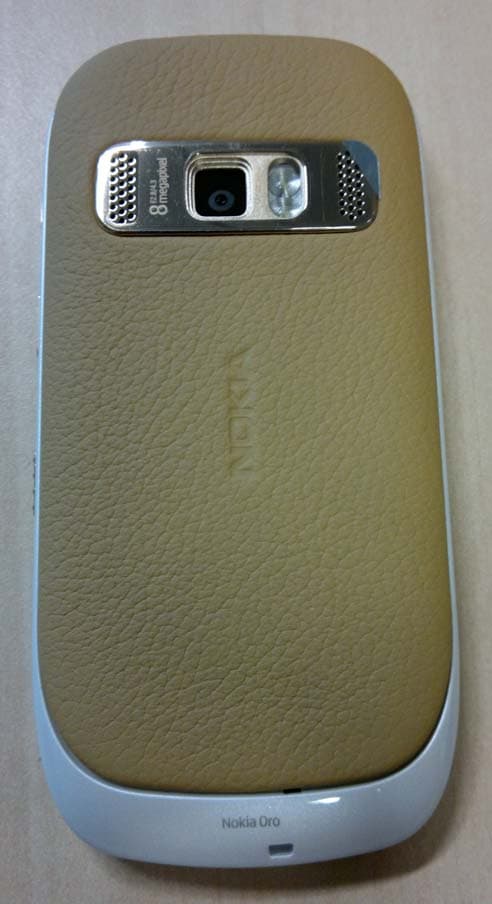
QFXRM-749
May 26, 2011GSM/WCDMA cellular telephone with BT, WLAN, FM Tx and RF ID
Equipment Class
DXX - Part 15 Low Power Communication Device Transmitter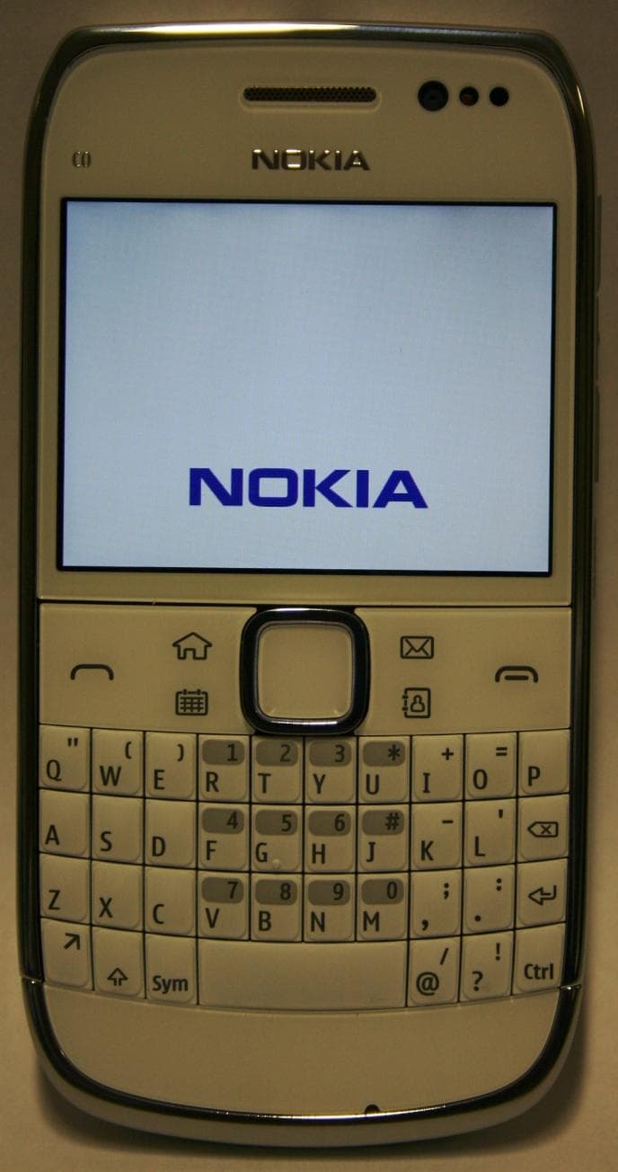
QFXRM-609
Mar 16, 2011GSM/WCDMA cellular telephone with Bluetooth and WLAN
Equipment Class
DSS - Part 15 Spread Spectrum Transmitter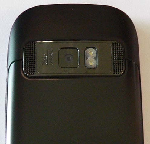
QFXRM-691
Mar 07, 2011GSM/WCDMA cellular telephone with BT, WLAN, FM Tx and RF ID
Equipment Class
DXX - Part 15 Low Power Communication Device Transmitter
QFXRM-744
Mar 07, 2011GSM/WCDMA cellular phone with Bluetooth
Equipment Class
DSS - Part 15 Spread Spectrum Transmitter
QFXRM-745
Mar 03, 2011GSM/WCDMA cellular phone with Bluetooth
Equipment Class
JBP - Part 15 Class B Computing Device Peripheral