QFXNHM-10XDual Band GSM phone with Bluetooth
Microsoft Corporation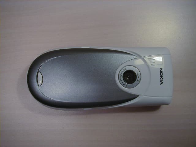
Click to zoom
Application Details
- Equipment Class
- PCE - PCS Licensed Transmitter held to ear
- Date of Grant
- Oct 26, 2003
- Application Purpose
- Original Equipment
- Date of Application
- Oct 26, 2003
- Equipment Note
- Dual Band GSM phone with Bluetooth
- Frequency Range
- 1850.20000000 - 1909.80000000
- Company
- Microsoft Corporation
- Country
- United States
Documents & Files
Document Text
Text extracted from the exhibit documents filed with the FCC. Open a document above to read the original.
Users Manual
Nokia 3620 and Nokia 3660 User Guide The wireless phones described in this guide are approved for use in the GSM network. LEGAL INFORMATION Part No. 9310245, Issue No. 1 1 1 Copyright ©2003 Nokia. All rights reserved. Nokia, Nokia Connecting People, Nokia 3620, Nokia 3660, and the Nokia Original Accessories logos are trademarks or registered trademarks of Nokia Corporation. All other product and company names mentioned herein may be trademarks or tradenames of their respective owners. Printed in Canada October 2003 US Patent No 5818437 and other pending patents. T9 text input software Copyright ©1999-2003. Tegic Communications, Inc. All rights reserved. Includes RSA BSAFE cryptographic or security protocol software from RSA Security. Java is a trademark of Sun Microsystems, Inc. Bluetooth is a registered trademark of Bluetooth SIG, Inc. The information in this user guide was written for the Nokia 3620 and Nokia 3660 phones. Nokia operates a policy of ongoing development. Nokia reserves the right to make changes and improvements to any of the products described in this document without prior notice. UNDER NO CIRCUMSTANCES SHALL NOKIA BE RESPONSIBLE FOR ANY LOSS OF DATA OR INCOME OR ANY SPECIAL, INCIDENTAL, AND CONSEQUENTIAL OR INDIRECT DAMAGES HOWSOEVER CAUSED. THE CONTENTS OF THIS DOCUMENT ARE PROVIDED “AS IS.” EXCEPT AS REQUIRED BY APPLICABLE LAW, NO WARRANTIES OF ANY KIND, EITHER EXPRESS OR IMPLIED, INCLUDING, BUT NOT LIMITED TO, THE IMPLIED WARRANTIES OF MERCHANTABILITY AND FITNESS FOR A PARTICULAR PURPOSE, ARE MADE IN RELATION TO THE ACCURACY AND RELIABILITY OR CONTENTS OF THIS DOCUMENT. NOKIA RESERVES THE RIGHT TO REVISE THIS DOCUMENT OR WITHDRAW IT AT ANY TIME WITHOUT PRIOR NOTICE. EXPORT CONTROLS This product contains commodities, technology or software exported from the United States in accordance with the Export Administration regulations. Diversion contrary to U.S. law is prohibited. FCC/INDUSTRY CANADA NOTICE Your phone may cause TV or radio interference (for example, when using a telephone in close proximity to receiving equipment). The FCC or Industry Canada can require you to stop using your telephone if such interference cannot be eliminated. If you require assistance, contact your local service facility. This device complies with part 15 of the FCC rules. This device contains a radio transceiver and digital circuitry that supports its features. Operation of the digital device circuitry is subject to the following two conditions: (1) this device may not cause harmful interference, and (2) this device must accept any interference received, including interference that may cause undesired operation. Modifications to this device not authorized by Nokia may void the authority granted for operation of this device and should not be made. [ iii ] Contents 1 For your safety . . . . . . . . . . . . . . . . . . . . . . . . . . . . . 1 2 General information . . . . . . . . . . . . . . . . . . . . . . . . . 3 Register your phone . . . . . . . . . . . . . . . . . . . . . . . . . . . . . . . . . . . . 3 Follow graphic clues . . . . . . . . . . . . . . . . . . . . . . . . . . . . . . . . . . . . 3 Network services. . . . . . . . . . . . . . . . . . . . . . . . . . . . . . . . . . . . . . . 3 Contact Nokia . . . . . . . . . . . . . . . . . . . . . . . . . . . . . . . . . . . . . . . . . 4 Learn about accessibility solutions . . . . . . . . . . . . . . . . . . . . . . . . 5 Nokia 3620 and Nokia 3660 phones at a glance . . . . . . . . . . . . . 6 Understand your phone . . . . . . . . . . . . . . . . . . . . . . . . . . . . . . . . . 7 Menu . . . . . . . . . . . . . . . . . . . . . . . . . . . . . . . . . . . . . . . . . . . . . . . 16 Options lists . . . . . . . . . . . . . . . . . . . . . . . . . . . . . . . . . . . . . . . . . 17 Navigation bar . . . . . . . . . . . . . . . . . . . . . . . . . . . . . . . . . . . . . . . 18 Actions common to all applications . . . . . . . . . . . . . . . . . . . . . . 18 Volume control . . . . . . . . . . . . . . . . . . . . . . . . . . . . . . . . . . . . . . . 20 Loudspeaker . . . . . . . . . . . . . . . . . . . . . . . . . . . . . . . . . . . . . . . . . 20 Headset . . . . . . . . . . . . . . . . . . . . . . . . . . . . . . . . . . . . . . . . . . . . . 21 Shared memory . . . . . . . . . . . . . . . . . . . . . . . . . . . . . . . . . . . . . . . 21 3 Your phone . . . . . . . . . . . . . . . . . . . . . . . . . . . . . . . 22 Make a call . . . . . . . . . . . . . . . . . . . . . . . . . . . . . . . . . . . . . . . . . . 22 Answer a call. . . . . . . . . . . . . . . . . . . . . . . . . . . . . . . . . . . . . . . . . 25 Log—Call log and general log . . . . . . . . . . . . . . . . . . . . . . . . . . . 27 SIM folder . . . . . . . . . . . . . . . . . . . . . . . . . . . . . . . . . . . . . . . . . . . 33 4 Settings. . . . . . . . . . . . . . . . . . . . . . . . . . . . . . . . . . 34 [ iv ] Change general settings. . . . . . . . . . . . . . . . . . . . . . . . . . . . . . . . 34 Phone settings . . . . . . . . . . . . . . . . . . . . . . . . . . . . . . . . . . . . . . . 34 Call settings . . . . . . . . . . . . . . . . . . . . . . . . . . . . . . . . . . . . . . . . . 36 Connection settings . . . . . . . . . . . . . . . . . . . . . . . . . . . . . . . . . . . 38 Access points . . . . . . . . . . . . . . . . . . . . . . . . . . . . . . . . . . . . . . . . 40 Date and time . . . . . . . . . . . . . . . . . . . . . . . . . . . . . . . . . . . . . . . . 45 Security . . . . . . . . . . . . . . . . . . . . . . . . . . . . . . . . . . . . . . . . . . . . . 46 Call restriction (system service). . . . . . . . . . . . . . . . . . . . . . . . . . 50 System . . . . . . . . . . . . . . . . . . . . . . . . . . . . . . . . . . . . . . . . . . . . . . 51 Accessory settings . . . . . . . . . . . . . . . . . . . . . . . . . . . . . . . . . . . . 51 5 Contacts. . . . . . . . . . . . . . . . . . . . . . . . . . . . . . . . . 52 Create contact cards . . . . . . . . . . . . . . …
Text truncated - open the document above for the full version.
Cover Letter(s)
CONFIDENTIAL 27 October 2003 Second Response to Issues raised on the NHM-10X FCC Application 1) We did not realize that the Bluetooth was a installed module. Part 15 (bluetooth approval) requires the top and bottom of each board photographed. Please provide an additional bottom photograph of the module. Response 1) As requested, an image of the underside of the Bluetooth Module is shown below. 2) For previous question 3), please confirm if the device is a dual-band or tri-band phone. Note that the theory of operation mentions dual-band Cell phone, but section 2 of the EMC report states tri-band. Please explain. Response 2) The NHM-10X phone is a dual-band phone; the tri-band reference in the EMC report is incorrect. 3) Previous question 7) & 8) should have stated that the VBW (not RBW) must be > 1/TX on time. Please recomment on this question. Response 3) I can confirm that the video bandwidth was greater than 1/TX on time; this can also be seen in the reported plots. The TX on time was measured and found to be 454.9 μS. Thus, 1/454.9 = 0.002 MHz (2kHz). This is significantly less than the bandwidths used for the measurements described in your ATCB response. Response to ATCB Questions FCC ID: QFX NHM-10X Applicant: Nokia Mobile Phones Copyright © 2003 Nokia
Cover Letter(s)
CONFIDENTIAL 24 October 2003 Response to Issues raised on the NHM-10X FCC Application 1) Please provide an additional photograph with the second sub-shield removed (page 6 of 8 in the Internal Photos exhibit). Response 1) The shield to which you refer is the shield associated with the Bluetooth Module, which is used in its entirety in the design of this product. To clarify the use of the module within the device, similar modules have been photographed (in the same orientation, with and without shield) adjacent to main circuit board. 2) The 731 form lists GSM frequencies for AMPS band as 824.2 - 848.2. It is our understanding that this should be 824.2 - 848.8 which does also match the test report. Please explain. Response 2) You are correct; an error was made during the completion of the form. Response to ATCB Questions FCC ID: QFX NHM-10X Applicant: Nokia Mobile Phones Copyright © 2003 Nokia CONFIDENTIAL 24 October 2003 3) For purposes of correctly listing information on the grant, is this phone a dual-band or tri-band. Note that the theory of operation mentions dual-band Cell phone, but section 2 of the EMC report states tri-band. Please explain. Response 3) An error in the report was not noticed prior to inclusion in the application documents 4) It does not appear that the DC voltages/currents applied into the several elements of the final radio frequency amplifying device for normal operation over the power range as required by 2.1033(c)(8) are listed. Please explain where this information is located, or provide this information separately. Response 4) The following table has been provided to identify the voltages and current required These measurements have been made on an unmodified NHM-10X device operating into 50R load. Ambient temperature, mid channel both bands. Battery voltage = 3.6V. Current and voltage is measured mid burst. 2.1033.c.8 does not state whether the max and min or the full range is necessary. These tables cover all. GSM850 GSM 1900 PCLCurrent / mA 1975 18100 17120 16145 15178 14220 13275 12345 11435 10545 9680 8860 71085 61370 51650 PCLCurrent / mA 1550 1455 1365 1278 1195 10110 9140 8180 7220 6280 5353 4450 3560 2710 1890 01090 5) The highest emissions shown in the plots in section 8.2 & 8.8 do not appear to be listed in the final data. Please explain. Response 5) There is a comment that accompanies the plots that explains they are pre-scans and thus for indication purposes only. Because of the nature of screen rooms on RF signals the limit was derived through substitution. It is not realistic to perform screen room substitution at every frequency point. Thus substitution is performed at the point that exhibits the worst response of the room. The limit is then constructed around this point. This ensures the tightest possible limit and this ultimately leads to over testing. The fact the pre-scan data is over the limit does not necessarily indicate a failure as it may have been over tested. Any spurious that resides within 20dB of the displayed limit, or over the limit is further analysed. The final data is thus recorded in a table that accompanies the graphs. The fact that no data has been reported for the spurious shown on the plot is an indication of the considerable effect the reflections of the screen room Response to ATCB Questions FCC ID: QFX NHM-10X Applicant: Nokia Mobile Phones Copyright © 2003 Nokia CONFIDENTIAL 24 October 2003 had on the emission, it was thus greatly reduced falling 20 dB below the appropriate limit once the EUT was set-up on the open area teat site (OATS). 6) It is not certain how the 232 hops in 31.5 seconds was obtained in section 8.6 of the test report. Note that if the device has 79 channels and occupies each for 454.909820uS, that this equates to a period for TX on all 79 channels of about 35.938 msec. Therefore in 30 seconds, the device will occupy a channel for 30/period of 834.8 times in 30 seconds. 834.8* TX duration measured is 379.7 msec. Please explain. Response 6) The 232 hops were noted by counting the number of peaks on the 3 rd Plot on page 24. The standard states that “The average time of occupancy on any channel shall not be greater than 0.4 seconds within a period of 0.4 seconds multiplied by the number of hopping channels employed”. From this a channel was picked, the pulse width and number of transmissions in the defined time were measured and counted. Thus :- 79 Channels x .4 Secs = 31.6 Secs Number of transmissions on any one channel in 31.6 Secs = 232 Maximum Packet Width on a Chosen Channel = 454.909820 μS Total transmission period in 31.6 Seconds on any one channel :- 232 * 454.909820 μS = 0.105539 Secs. 7) Typically for narrow band emissions given in sections 8.8 of the report, the average to peak measurements made on this type of device are 0 to only a few dB difference. The delta between the peak and average is typically on the order of 15 dB or more. This suggests that the device was transmitting in a frequency stopped pulse mode of operation instead of a CW signal that is expected according to FCC measurements on this type of device. Due to variances in average detectors, FHSS systems or any type of pulsed waveform are mathematically corrected for the average measurement instead of actually providing measurements during pulsed modes. Otherwise any average measurements employed must assure that the RBW > 1/TX on time. Given that this device uses Bluetooth, the theory may actually be applied for these measurements. Note that Bluetooth has different packet lengths that may be used in modes with longer packets. The theory of operation for Bluetooth states that there may be 1, 3, or 5 slots used per transmit depending on the mode of operation. For a DH1 packet the TX is on 0.625 us per 49 mS per channel, while for a DH5 packet the TX is on 0.625 * 5 per 247 ms per channel. These duty cycles equal the following: 20 log (.625/49) = 37.9 dB or 20 log (3.125/100) = -30 dB. All modes are greater than the 20dB diff…
Text truncated - open the document above for the full version.
Cover Letter(s)
American Telecommunications Certification Body Inc. 6731 Whittier Ave, McLean, VA 22101 October 17, 2003 RE: Nokia UK Ltd. FCC ID: QFXNHM-10X After a review of the submitted information, I have a few comments on the above referenced Application. 1) Please provide an additional photograph with the second sub-shield removed (page 6 of 8 in the Internal Photos exhibit). 2) The 731 form lists GSM frequencies for AMPS band as 824.2 - 848.2. It is our understanding that this should be 824.2 - 848.8 which does also match the test report. Please explain. 3) For purposes of correctly listing information on the grant, is this phone a dual-band or tri-band. Note that the theory of operation mentions dual-band Cell phone, but section 2 of the EMC report states tri-band. Please explain. 4) It does not appear that the DC voltages/currents applied into the several elements of the final radio frequency amplifying device for normal operation over the power range as required by 2.1033(c)(8) are listed. Please explain where this information is located, or provide this information separately. Bluetooth Report 5) The highest emissions shown in the plots in section 8.2 & 8.8 do not appear to be listed in the final data. Please explain. 6) It is not certain how the 232 hops in 31.5 seconds was obtained in section 8.6 of the test report. Note that if the device has 79 channels and occupies each for 454.909820uS, that this equates to a period for TX on all 79 channels of about 35.938 msec. Therefore in 30 seconds, the device will occupy a channel for 30/period of 834.8 times in 30 seconds. 834.8* TX duration measured is 379.7 msec. Please explain. 7) Typically for narrow band emissions given in sections 8.8 of the report, the average to peak measurements made on this type of device are 0 to only a few dB difference. The delta between the peak and average is typically on the order of 15 dB or more. This suggests that the device was transmitting in a frequency stopped pulse mode of operation instead of a CW signal that is expected according to FCC measurements on this type of device. Due to variances in average detectors, FHSS systems or any type of pulsed wavefore are mathematically corrected for the average measurement instead of actually providing measurements during pulsed modes. Otherwise any average measurements employed must assure that the RBW > 1/TX on time. Given that this device uses Bluetooth, the theory may actually be applied for these measurements. Note that Bluetooth has different packet lengths that may be used in modes with longer packets. The theory of operation for Bluetooth states that their may be 1, 3, or 5 slots used per transmit depending on the mode of operation. For a DH1 packet the TX is on 0.625 us per 49 mS per channel, while for a DH5 packet the TX is on 0.625 * 5 per 247 ms per channel. These duty cycles equal the following: 20 log (.625/49) = 37.9 dB or 20 log (3.125/100) = -30 dB. All modes are greater than the 20 dB difference between the peak and average limits. Given the acceptable nature of bluetooth duty cycles, you may apply this justification for these measurements. Alternatively, you may simply provide a statement in the report that peak measurements met with average limits without actually showing any average measurements since this is the case. Please comment and/or correct the report as necessary. 8) Similar concerns are noted regarding section 8.9 of the report. It is recommended to apply the mathematical correction vs. actual measurements. --- Continue on Next Page --- z Page 2October 17, 2003 Part 22/24 Report 9) The prescan results show in section 8.2 amd 10.2 appear to show results significantly above the limits. Please explain. SAR Report 10) The FCC asks that the SAR laboratory re-measure the peak power to ensure that the device is fully functioning during the SAR test at maximum TX power. Reported power results appear to be identical to EMC EIRP reported values. Conducted power appear to be given in the SAR report page 14. However, were conducted measurements made during EMC testing? What assurance can be provided that the device was functioning correctly at full maximum power during the SAR test. 11) Are full test configuration photographs available? If so please provide. 12) Review of the users manual lists multiple accessories (LPS-3 Inductive Loopset, HDC-5 Headset, HDE-2 Headset, HDD-1 Headset, HDC-10 Headset, and HDB-5). However it appears that only the HDE-2 Headset was tested. Since not all combinations have been tested, a justification must be made as to the determination of the worse case configuration(s). 13) The SAR Phantom description (section 4.2) should include relative thickness and tolerance information. 14) The FCC asks that the liquid dielectric parameters should measured at device mid-band frequencies. It appears that for the Part 24 band that these were measured at 1900 MHz vs approximately 1880. Please provide this missing information. 15) What was the probe tip distance to phantom inner surface during course scans? 16) The Distance between the measurement point (distance + offset) at the probe sensor location (geometric center behind the probe tip) and the phantom surface should be less than is < 8.0 mm and maintained at a constant distance of +/- 1.0 mm during an area scan to determine peak SAR locations. From reviewing the Z-axis scan for RH Tilt, it appears that the distance of < 8.0 mm might not have been achieved (appox 6 + 2.7 mm > 8.0 mm). Please explain. Timothy R. Johnson Examining Engineer mailto: [email protected] The items indicated above must be submitted before processing can continue on the above referenced application. Failure to provide the requested information may result in application termination. Correspondence should be considered part of the permanent submission and may be viewed from the Internet after a Grant of Equipment Authorization is issued. Please do not respond to this correspondence using the email r…
Text truncated - open the document above for the full version.
Cover Letter(s)
American Telecommunications Certification Body Inc. 6731 Whittier Ave, McLean, VA 22101 October 23, 2003 RE: Nokia UK Ltd. FCC ID: QFXNHM-10X After a review of the submitted information, I have a few comments on the above referenced Application. 1) We did not realize that the Bluetooth was a installed module. Part 15 (bluetooth approval) requires the top and bottom of each board photographed. Please provide an additional bottom photograph of the module. 2) For previous question 3), please confirm if the device is a dual-band or tri-band phone. Note that the theory of operation mentions dual-band Cell phone, but section 2 of the EMC report states tri-band. Please explain. Bluetooth Report 3) Previous question 7) & 8) should have stated that the VBW (not RBW) must be > 1/TX on time. Please recomment on this question. Timothy R. Johnson Examining Engineer mailto: [email protected] The items indicated above must be submitted before processing can continue on the above referenced application. Failure to provide the requested information may result in application termination. Correspondence should be considered part of the permanent submission and may be viewed from the Internet after a Grant of Equipment Authorization is issued. Please do not respond to this correspondence using the email reply button. In order for your response to be processed expeditiously, you must submit your documents through the AmericanTCB.com website. Also, please note that partial responses increase processing time and should not be submitted. Any questions about the content of this correspondence should be directed to the sender.
External Photos
CONFIDENTIAL 30 September 2003 Photographs of the Equipment NHM-10 Photograph No 1 Exhibit 03: External Photographs FCC ID: QFX NHM-10X Applicant: Nokia Mobile Phones Copyright © 2003 Nokia CONFIDENTIAL 30 September 2003 Photograph No 2 Exhibit 03: External Photographs FCC ID: QFX NHM-10X Applicant: Nokia Mobile Phones Copyright © 2003 Nokia CONFIDENTIAL 30 September 2003 Photograph No 3 Exhibit 03: External Photographs FCC ID: QFX NHM-10X Applicant: Nokia Mobile Phones Copyright © 2003 Nokia
ID Label/Location Info
CONFIDENTIAL 02 October 2003 Location of Identification Label for NHM-10 Photograph No 1 Exhibit 01: Label and Location FCC ID: QFX NHM-10X Applicant: Nokia Mobile Phones Copyright © 2003 Nokia CONFIDENTIAL 02 October 2003 Exhibit 01: Label and Location FCC ID: QFX NHM-10X Applicant: Nokia Mobile Phones Copyright © 2003 Nokia
Internal Photos
CONFIDENTIAL 02 October 2003 Exhibit 09: Internal Photograph FCC ID: QFX NHM-10X Applicant: Nokia Mobile Phones Copyright © 2003 Nokia CONFIDENTIAL 02 October 2003 Exhibit 09: Internal Photograph FCC ID: QFX NHM-10X Applicant: Nokia Mobile Phones Copyright © 2003 Nokia CONFIDENTIAL 02 October 2003 Exhibit 09: Internal Photograph FCC ID: QFX NHM-10X Applicant: Nokia Mobile Phones Copyright © 2003 Nokia CONFIDENTIAL 02 October 2003 Exhibit 09: Internal Photograph FCC ID: QFX NHM-10X Applicant: Nokia Mobile Phones Copyright © 2003 Nokia CONFIDENTIAL 02 October 2003 Exhibit 09: Internal Photograph FCC ID: QFX NHM-10X Applicant: Nokia Mobile Phones Copyright © 2003 Nokia CONFIDENTIAL 02 October 2003 Exhibit 09: Internal Photograph FCC ID: QFX NHM-10X Applicant: Nokia Mobile Phones Copyright © 2003 Nokia CONFIDENTIAL 02 October 2003 Exhibit 09: Internal Photograph FCC ID: QFX NHM-10X Applicant: Nokia Mobile Phones Copyright © 2003 Nokia CONFIDENTIAL 02 October 2003 Exhibit 09: Internal Photograph FCC ID: QFX NHM-10X Applicant: Nokia Mobile Phones Copyright © 2003 Nokia
RF Exposure Info
Salo SAR Report SAR0333_01 Applicant: Nokia Corporation Type: NHM-10 Copyright 2003 TCC Salo 2/48 CONTENTS CONTENTSCONTENTS CONTENTS 1. 1.1. 1. SUMMARY OF SAR TEST SUMMARY OF SAR TEST SUMMARY OF SAR TEST SUMMARY OF SAR TEST REPORT REPORTREPORT REPORT................................ ................................................................ ................................................................ ................................................................ ................................................................ ................................................................ ................................................................ ................................................................ ............................................. .......................... ............. 3 33 3 1.1 TEST DETAILS.............................................................................................................................................................................3 1.2 MAXIMUM RESULTS....................................................................................................................................................................3 1.2.1 Head Configuration........................................................................................................................................................ 3 1.2.2 Body Worn Configuration ............................................................................................................................................ 3 1.2.3 Maximum Drift ................................................................................................................................................................ 3 1.2.4 Measurement Uncertainty ........................................................................................................................................... 3 2. 2.2. 2. DESCRIPTION OF THE D DESCRIPTION OF THE DDESCRIPTION OF THE D DESCRIPTION OF THE DEVICE U EVICE UEVICE U EVICE UNDER TEST (DUT) NDER TEST (DUT)NDER TEST (DUT) NDER TEST (DUT) ................................ ................................................................ ................................................................ ................................................................ ................................................................ ................................................................ ............................................... .............................. ............... 4 44 4 2.1 PICTURE OF DEVICE....................................................................................................................................................................4 2.2 DESCRIPTION OF THE ANTENNA..................................................................................................................................................4 2.3 BATTERIES.................................................................................................................................................................................4 2.4 HEADSETS..................................................................................................................................................................................4 3. 3.3. 3. TEST CONDITIONS TEST CONDITIONSTEST CONDITIONS TEST CONDITIONS ................................ ................................................................ ................................................................ ................................................................ ................................................................ ................................................................ ................................................................ ................................................................ ................................................................ ................................................................ ..................................... .......... ..... 5 55 5 3.1 TEMPERATURE AND HUMIDITY....................................................................................................................................................5 3.2 TEST SIGNAL, FREQUENCIES, AND OUTPUT POWER....................................................................................................................5 4. 4.4. 4. DESCRIPTION OF THE T DESCRIPTION OF THE TDESCRIPTION OF THE T DESCRIPTION OF THE TEST EQUIPMENT EST EQUIPMENTEST EQUIPMENT EST EQUIPMENT ................................ ................................................................ ................................................................ ................................................................ ................................................................ ................................................................ ............................................................... .............................................................. ............................... 5 55 5 4.1 MEASUREMENT SYSTEM AND COMPONENTS.................................................................................................................................5 4.1.1 Isotropic E-field probe SN: 1396................................................................................................................................. 6 4.2 PHANTOMS................................................................................................................................................................................7 4.3 SIMULATING LIQUIDS.................................................................................................................................................................7 4.3.1 Liquid recipes................................................................................................................................................................... 7 4.3.2 Verification of…
Text truncated - open the document above for the full version.
Test Report
Radio Frequency Investigation Ltd, Ewhurst Park, Ramsdell, Basingstoke, Hampshire, RG26 5RQ, ENGLAND. Tel: +44 (0) 1256 851193 Fax: +44 (0) 1256 851192 Registered in England, No. 211 7901. Registered Office: Ewhurst Park, Ramsdell, Basingstoke, Hampshire RG26 5RQ 0644 TEST REPORT FROM RADIO FREQUENCY INVESTIGATION LTD. Test Of: Nokia Mobile Phones. NHM-10 Model 3620 To: FCC Part 22 and 24 Test Report Serial No: RFI/MPTB2/RP45157JD01A Supersedes Test Report Serial No: RFI/MPTB1/RP45157JD01A This Test Report Is Issued Under The Authority Of Richard Jacklin, Operations Director: Checked By: Tested By: Release Version No: PDF01 Issue Date: 02 October 2003 Test Dates: 19 August 2003 to 11 September 2003 This report is issued in Adobe Acrobat portable document format (PDF). It is only a valid copy of the report if it is being viewed in PDF format with the following security options not allowed: Changing the document, Selecting text and graphics, Adding or changing notes and form fields. Furthermore, the date of creation must match the issue date stated above. This report may be copied in full. The results in this report apply only to the sample(s) tested. RADIO FREQUENCY I…
Text truncated - open the document above for the full version.
Contact Information
Applicant
Hasnain Syed(Director, EMC, SI and RF Compliance)
Technical Contact
Nokia UK LtdAndrew White
[email protected]011 44 1252 866366
Summit Avenue · Farnborough, Hampshire · United Kingdom
Non-Technical Contact
Nokia UK LtdAndrew White
[email protected]011 44 1252 866366
Test Firm
Nokia UK LtdAndrew Sinclair
Technical Specifications
| # | Rule Parts | Frequency Range | Power Output | Emission | Tolerance |
|---|---|---|---|---|---|
| 2 | 24E | 1.85 GHz - 1.91 GHz | 1.905 W | 300KGXW | 0.1 ppm |
Other Applications from Microsoft Corporation
QFXRM-749
May 26, 2011GSM/WCDMA cellular telephone with BT, WLAN, FM Tx and RF ID
Equipment Class
DXX - Part 15 Low Power Communication Device Transmitter
QFXRM-609
Mar 16, 2011GSM/WCDMA cellular telephone with Bluetooth and WLAN
Equipment Class
DSS - Part 15 Spread Spectrum Transmitter
QFXRM-691
Mar 07, 2011GSM/WCDMA cellular telephone with BT, WLAN, FM Tx and RF ID
Equipment Class
DXX - Part 15 Low Power Communication Device Transmitter
QFXRM-744
Mar 07, 2011GSM/WCDMA cellular phone with Bluetooth
Equipment Class
DSS - Part 15 Spread Spectrum Transmitter
QFXRM-745
Mar 03, 2011GSM/WCDMA cellular phone with Bluetooth
Equipment Class
JBP - Part 15 Class B Computing Device Peripheral