QGH-47611-WG4300Mbps Daul Band 802.11n Wireless Gigabit Router
Leviton Manufacturing Co., Inc.
Click to zoom
Application Details
- Equipment Class
- DTS - Digital Transmission System
- Date of Grant
- Mar 16, 2014
- Application Purpose
- Original Equipment
- Date of Application
- Mar 11, 2014
- Equipment Note
- 300Mbps Daul Band 802.11n Wireless Gigabit Router
- Frequency Range
- 5745.00000000 - 5825.00000000
- Country
- United States
Documents & Files
Document Text
Text extracted from the exhibit documents filed with the FCC. Open a document above to read the original.
Users Manual
I Copyright Copyright ¤ 2014 by Leviton Manufacturing Co., Inc. All rights reserved. No part of this publication may be reproduced, transmitted, transcribed, stored in a retrieval system, or translated into any language or computer language, in any form or by any means, electronic, mechanical, magnetic, optical, chemical, manual or otherwise, without the prior written permission of LEVITON. LEVITON makes no representations or warranties, either expressed or implied, with respect to the contents hereof and specifically disclaims any warranties, merchantability or fitness for any particular purpose. Any software described in this manual is sold or licensed "as is". Should the programs prove defective following their purchase, the buyer (and not this company, its distributor, or its dealer) assumes the entire cost of all necessary servicing, repair, and any incidental or consequential damages resulting from any defect in the software. Further, this company reserves the right to revise this publication and to make changes from time to time in the contents hereof without obligation to notify any person of such revision or changes. All brand and product names mentioned in this manual are trademarks and/or registered trademarks of their respective holders. Federal Communication Commission Interference Statement This equipment has been tested and found to comply with the limits for a Class B digital device, pursuant to Part 15 of FCC Rules. These limits are designed to provide reasonable protection against harmful interference in a residential installation. This equipment generates uses and can radiate radio frequency energy and, if not installed and used in accordance with the instructions, may cause harmful interference to radio communications. However, there is no guarantee that interference will not occur in a particular installation. If this equipment does cause harmful interference to radio or television reception, which can be determined by turning the equipment off and on, the user is encourages to try to correct the interference by one or more of the following measures: 1. Reorient or relocate the receiving antenna. 2. Increase the separation between the equipment and receiver. 3. Connect the equipment into an outlet on a circuit different from that to which the receiver is connected. 4. Consult the dealer or an experienced radio technician for help. FCC and IC Statement: To assure continued compliance, (example-use only shielded interface cables when connecting to computer or peripheral devices) any changes or modifications not expressly approved by the party responsible for compliance could void the user’s authority to operate the equipment. This device complies with Part 15 of the FCC Rules and Industry Canada licence-exempt RSS standard(s). Operation is subject to the Following two conditions: (1) This device may not cause harmful interference (2) This Device must accept any interference received, including interference that may cause undesired operation. Le présent appareil est conforme aux CNR d'Industrie Canada applicables aux appareils radio exempts de licence. L'exploitation est autorisée aux deux conditions suivantes : (1) l'appareil ne doit pas produire de brouillage, et (2) l'utilisateur de l'appareil doit accepter tout brouillage radioélectrique subi, même si le brouillage est susceptible d'en compromettre le fonctionnement. Any changes or modifications not expressly approved by the party responsible for compliance could void the user’s authority to operate the equipment. II Canadian Department of Communications The device meets the exemption from the routine evaluation limits in section 2.5 of RSS 102 and compliance with RSS-102 RF exposure, users can obtain Canadian information on RF exposure and compliance. Le dispositif rencontre l'exemption des limites courantes d'évaluation dans la section 2.5 de RSS 102 et la conformité à l'exposition de RSS-102 rf, utilisateurs peut obtenir l'information canadienne sur l'exposition et la conformité de rf. Federal Communication Commission (FCC) Radiation Exposure Statement This equipment complies with FCC radiation exposure set forth for an uncontrolled environment. In order to avoid the possibility of exceeding the FCC radio frequency exposure limits, human proximity to the antenna shall not be less than 20 cm (8 inches) during normal operation. The device in the 5150-5250 MHz band is for indoor use only. R&TTE Compliance Statement This equipment complies with all the requirements of DIRECTIVE 1999/5/CE OF THE EUROPEAN PARLIAMENT AND THE COUNCIL OF 9 March 1999 on radio equipment and telecommunication terminal Equipment and the mutual recognition of their conformity (R&TTE). The R&TTE Directive repeals and replaces in the directive 98/13/EEC (Telecommunications Terminal Equipment and Satellite Earth Station Equipment) As of April 8, 2000. Safety This equipment is designed with the utmost care for the safety of those who install and use it. However, special attention must be paid to the dangers of electric shock and static electricity when working with electrical equipment. All guidelines of this and of the computer manufacture must therefore be allowed at all times to ensure the safe use of the equipment. WEEE regulation To avoid the potential effects on the environment and human health as a result of the presence of hazardous substances in electrical and electronic equipment, end users of electrical and electronic equipment should understand the meaning of the crossed-out wheeled bin symbol. Do not dispose of WEEE as unsorted municipal waste and have to collect such WEEE separately. Revision User Manual for LEVITON 300Mbps Dual Band 802.11n Wireless Gigabit Router Model: 47611-WG4 Rev: 1.3 (March, 2014) III CONTENTS Chapter 1.Product Introduction ........................................................................................................... 1 1.1Package Contents ..........................................................…
Text truncated - open the document above for the full version.
Users Manual
User Manual of 47611-WG4 -56- Figure 5-3-22 User Manual of 47611-WG4 -57- 5.4 Advanced Settings “Advanced Settings” includes the following 6 submenus. Clicking any of them enters corresponding interface for configuration. Below explains, in details, each such feature. 5.4.1 Virtual Server The Virtual Server feature grants Internet users access to services on your LAN. It is useful for hosting online services such as FTP, Web, or game servers. For each Virtual Server, you define a WAN port on your router for redirection to an internal LAN IP Address and LAN port. Figure 5-4-1 Click “Add” to display below page. User Manual of 47611-WG4 -58- Figure 5-4-2 The page includes the following fields: ObjectDescription xWAN Port: Enter the WAN service port. xWell-Known Service Ports: The “Well-Known Service Port” lists commonly used protocol ports such as: Leviton S&A Controller (4369) DNS (53α FTP (21) GOPHER (70) HTTP (80) NNTP (1190) POP3 (110) PPTP (1723) SMTP (25) SOCK (1080) TELNET(23) In case that you don’t find the port ID you need, add it manually. xLAN Port: Enter LAN service port. xLAN IP: The IP address of a computer used as a server in LAN. xProtocol: Includes TCP,UDP and Both. Select “Both” if you are not sure about which protocol to use. xEnable: Check the “Enable” option to activate corresponding entry. For example: If you create a web server using port 80 on a LAN PC at the IP address of 192.168.0.100, and you want WAN users to access such server via http://x.x.x.x:4000 (x.x.x.x represents router’s WAN IP address), then do as follows: User Manual of 47611-WG4 -59- 1)Enter “4000” in WAN Port field, 80 in LAN port field and 192.168.0.100 in Private IP field, 2)Select “Both” from protocol drop-down list. 3)Check the “Enable” box. 4)Click “Save” to save such settings. Figure 5-4-3 Setting WAN port hereon to the same value as that on WAN access control section will deactivate the virtual server feature. 5.4.2 DMZ Settings to set a computer to be completely exposed to extranet for implementation of a In some cases, we need bidirectional communication. To do so, we set it as a DMZ host. User Manual of 47611-WG4 -60- Figure 5-4-4 The page includes the following fields: ObjectDescription xDMZ Host IP Address: Enter the IP address of a LAN computer which you want to set to a DMZ host. xEnable: Check/uncheck to enable/disable the DMZ host. 1. If you set a PC to a DMZ host, it will be completely exposed to extranet and gains no more protection from the device firewall. 2. 2. A WAN user accesses the Dcorresponding WAN IP address. MZ host through a 5.4.3 and Pls that eature. UPnP Settings UPnP (Universal Plug support such UPnP f ay) requires Windows ME/Windows XP or later or application software Figure 5-4-5 The page includes the following fields: ObjectDescription xID: Entry ID. xRemote Host: Description of a remote host that receives/sends responses. xWAN Port: Port on router side. xLAN Host: Description of an internal host that receives/sends responses. xLAN Port: Port on host side. xProtocol: Indicates whethe or UDP port forwarding r to perform TCP xDescription: Software info of a mapped port. User Manual of 47611-WG4 -61- 5.4.4g lks about RoutingdStatic Routing features. Routin This section ta Table an Routing Table This puter’s core rouch lists destination IP, subnet mask, gateway, hop count age displays the roting table whi and interface. Figure 5-4-6 Static Routing You can use this section to set up router’s static routing feature. Figure 5-4-7 Click “Add” to add static routing entries. Figure 5-4-8 The page includes the following fields: User Manual of 47611-WG4 -62- ObjectDescription xDestination Network: Enter a destination IP address. xSubnet Mask: Enter a Subnet Mask that corresponds to the destination IP address you entered. xGateway: Next-hop IP address. 5.4.5 Bandwidth Control To better manage bandwidth allocation and optimize network performance, use the Custom Bandwidth Allocation feature. Figure 5-4-9 e following fields: The page includes th ObjectDescription xCustom Bandwidth Allocation: Select this option to customize a bandwidth allocation policy that best fits your network. You can set specific limits on uplink and downlink bandwidth of PCs within a specified IP range. lick “Add” to display the page below: Figure 5-4-10 C User Manual of 47611-WG4 -63- Figure 5-4-11 The page includes the following fields: ObjectDescription xEnable: Check/uncheck to enable/disable current bandwidth entry xIP Range: Enter a single IP or an IP range. xUpstream Bandwidth Limit: Max total upload bandwidth for a specified PC or a range of PCs. xDownstream Bandwidth Limit: Max total download bandwidth for a specified PC or a range of PCs xP2P Download Control: Regulates P2P dowre each user a guaranteed share of bandwidth. nload rate to ensu xn Mode: er- al (Each member of the IP range shall utilize the allocated bandwidth individually)" he allocated Select eith Allocatio "Individu "Collective (All members of the IP range shall share t bandwidth collectively)" xAllocation Policy: Select either "Utilize only the allocated bandwidth" or "Utilize more bandwidth if available" xDescription: Brief description of current entry. User Manual of 47611-WG4 -64- 1. Please n 2. If you enableol feature, it will limit P2P download rate (sm browsire of bandwidth. 3. If you sele wn to ensure defined and additional bandwidth if available o ote the bandwidth unit. the P2P Download Contr aller than the specified value) to ensure other applications such as web ng a reserved and guaranteed sha ct "Utilize more bandwidth if available", router will dynamically adjust nlink bandwidth allocatiouplink/do r only defined bandwidth. For If you want and 2M downlink banown on the scree example: each PC within the IP range of 192.168.0.100-192.168.0.120 to have up to 2M uplink dwidth, and want to control P2P download bandwidth, then configure same settings as sh n below on your router: Figure 5-4-12 Use…
Text truncated - open the document above for the full version.
Cover Letter(s)
CERTIFICATE OF COMPLIANCE Authorized under Declaration of Conformity according to 47 CFR, Part 2 and Part 15 of the FCC Rules. The product listed in follows was (were) tested in the Neutron EMC Laboratory to comply with the criteria limits Class B of conducted and radiated emissions of the Technical Standards FCC Part 15, Subpart B, established by the FCC, USA. Equipment 300Mbps Dual Band 802.11n Wireless Gigabit Router Model Name 47611-WG4 Brand Name Leviton Applicant Leviton Manufacturing Co., Inc. Address 201 North Service Road Melville, NY 11747 Standard(s) FCC Part 15, Subpart B: 2012 ANSI C63.4 -2009 Report(s) NEI-FCCE-1-1401C081 The test data, data evaluation, and equipment configuration contained in our test report(s) above was(were) obtained utilizing the test procedures, test instruments, test sites that has been accredited by the Authority of TAF according to the ISO-17025 quality assessment standard and technical standard(s). The test data contained in the referenced test report relate only to the EUT sample and item(s) tested. Andy Chiu Authorized Signatory Neutron Engineering Inc. B1, No.37, Lane 365, Yang Guang St., NeiHu District 114., Taipei, Taiwan TEL:+886-2-2657-3299 FAX:+886-2-2657-3331
External Photos
Neutron Engineering Inc. Project No.: 1401C081 Page 1 of 12 ATTACHMENT PHOTOGRAPHS OF EUT Neutron Engineering Inc. Project No.: 1401C081 Page 2 of 12 Neutron Engineering Inc. Project No.: 1401C081 Page 3 of 12 Neutron Engineering Inc. Project No.: 1401C081 Page 4 of 12 Neutron Engineering Inc. Project No.: 1401C081 Page 5 of 12 Neutron Engineering Inc. Project No.: 1401C081 Page 6 of 12
Internal Photos
Neutron Engineering Inc. Project No.: 1401C081 Page 7 of 12 main board Neutron Engineering Inc. Project No.: 1401C081 Page 8 of 12 Neutron Engineering Inc. Project No.: 1401C081 Page 9 of 12 5G RF module IC Neutron Engineering Inc. Project No.: 1401C081 Page 10 of 12 5G RF Module Crystal 2.4G RF Module IC Neutron Engineering Inc. Project No.: 1401C081 Page 11 of 12 2.4G RF Module Crystal RF Module Antenna Neutron Engineering Inc. Project No.: 1401C081 Page 12 of 12
RF Exposure Info
Neutron Engineering Inc. FCC RF EXPOSURE REPORT FCC ID: QGH-47611-WG4 Project No. : 1401C081 Equipment : 300Mbps Dual Band 802.11n Wireless Gigabit Router Model : 47611-WG4 Applicant : Leviton Manufacturing Co., Inc.. Address : 201 North Service Road Melville,NY 11747 According: : FCC Guidelines for Human Exposure IEEE C95.1 Neutron Engineering Inc. No.3, Jinshagang 1st Road, ShiXia, Dalang Town, Dong Guan, China. TEL : (0769) 8318-3000 FAX : (0769) 8319-6000 Neutron Engineering Inc. MPE CALCULATION METHOD: Calculation Method of RF Safety Distance: where: S = power density P = power input to the antenna G = power gain of the antenna in the direction of interest relative to an isotropic radiator R = distance to the center of radiation of the antenna Table for Filed Antenna—2.4G Ant. Brand Model Name Antenna Type Connector Gain (dBi) 1 N/A Q5062 Dipole Antenna N/A 2.53 2 N/A Q5063 Dipole Antenna N/A 2.83 Table for Filed Antenna--5G Band 1 Ant. Brand Model Name Antenna Type Connector Gain (dBi) 1 N/A Q5062 Dipole Antenna N/A 3.8 2 N/A Q5063 Dipole Antenna N/A 3.72 Table for Filed Antenna--5G Band 4 Ant. Brand Model Name Antenna Type Connector Gain (dBi) 1 N/A Q5062 Dipole Antenna N/A 3.54 2 N/A Q5063 Dipole Antenna N/A 3.57 Neutron Engineering Inc. TEST RESULTS EUT: 300Mbps Dual Band 802.11n Wireless Gigabit Router Model Name : 47611-WG4 Temperature: 25 °C Relative Humidity: 55 % Test Voltage : AC 120V/60Hz Anten na Gain (dBi) Antenna Gain (numeric) Peak Output Power (dBm) Peak Output Power (mW) Power Density (S) (mW/cm 2 ) Limit of Power Density (S) (mW/cm 2 ) Te s t Result Note 3.57 2.2751 22.86 193.19680.08748838 1 Complies 5G 2.83 1.9187 24.15 260.01600.09930026 2.4G 0.18678864 To t a l The calculated distance is 20 cm
Test Report
Neutron Engineering Inc. Report No.: NEI-FCCP-1-1401C081 Page 1 of 128 FCC Radio Test Report FCC ID: QGH-47611-WG4 This report concerns (check one): Original Grant Class II Change Issued Date : Jan. 26, 2014 Project No. : 1401C081 Equipment : 300Mbps Dual Band 802.11n Wireless Gigabit Router Model Name : 47611-WG4 Applicant : Leviton Manufacturing Co., Inc. Address : 201 North Service Road Melville, NY 11747 Tested by: Neutron Engineering Inc. EMC Laboratory Date of Receipt: Jan. 14, 2014 Date of Test: Jan. 14, 2014 ~ Jan. 25, 2014 Testing Engineer : (David Mao) Technical Manager : (Leo Hung) Authorized Signatory: (Steven Lu) Neutron Engineering Inc. No.3,Jinshagang 1st Road, ShiXia, Dalang Town, Dong Guan, China. TEL: 0769-8318-3000 FAX: 0769-8319-6000 Neutron Engineering Inc. Report No.: NEI-FCCP-1-1401C081 Page 2 of 128 Declaration Neutron represents to the client that testing is done in accordance with standard procedures as applicable and that test instruments used has been calibrated with the standards traceable to National Measurement Laboratory (NML) of R.O.C, or National Institute of Standards and Technology (NIST) of U.S.A. Neutron's reports apply only to the specific samples tested under conditions. It is manufacture’s responsibility to ensure that additional production units of this model are manufactured with the identical electrical and mechanical components. Neutron shall have no liability for any declarations, inferences o r generalizations drawn by the client or others from Neutron issued reports. Neutron’s reports must not be used by the client to claim product endorsement by the authorities or any agency of the Government. This report is the confidential property of the client. As a mutual protection to the clients, the public and Neutron-self, extracts from the test report shall not be reproduced except in full with Neutron’s authorized written approval. Neutron’s laboratory quality assurance procedures are in compliance with the ISO Guide 17025 requirements, and accredited by the conformity assessment authorities listed in this test report. Limitation For the use of the authority's logo is limited unless the Test Standard(s)/Scope(s)/Item(s) mentioned in this test report is (are) included in the conformity assessment authorities acceptance respective. Neutron Engineering Inc. Report No.: NEI-FCCP-1-1401C081 Page 3 of 128 Table of Contents Page 1 . CERTIFICATION 6 2 . SUMMARY OF TEST RESULTS 7 2.1 TEST FACILITY 8 2.2 MEASUREMENT UNCERTAINTY 8 3 . GENERAL INFORMATION 9 3.1 GENERAL DESCRIPTION OF EUT 9 3.2 DESCRIPTION OF TEST MODES 11 3.3 TABLE OF PARAMETERS OF TEXT SOFTWARE SETTING 12 3.4 BLOCK DIAGRAM SHOWING THE CONFIGURATION OF SYSTEM TESTED 13 3.5 DESCRIPTION OF SUPPORT UNITS 14 4 . EMC EMISSION TEST 15 4.1 CONDUCTED EMISSION MEASUREMENT 15 4.1.1 POWER LINE CONDUCTED EMISSION LIMITS 15 4.1.2 TEST PROCEDURE 15 4.1.3 DEVIATION FROM TEST STANDARD 15 4.1.4 TEST SETUP 16 4.1.5 EUT OPERATING CONDITIONS 16 4.1.6 EUT TEST CONDITIONS 16 4.1.7 TEST RESULTS 16 4.2 RADIATED EMISSION MEASUREMENT 19 4.2.1 RADIATED EMISSION LIMITS 19 4.2.2 TEST PROCEDURE 20 4.2.3 DEVIATION FROM TEST STANDARD 20 4.2.4 TEST SETUP 21 4.2.5 EUT OPERATING CONDITIONS 22 4.2.6 EUT TEST CONDITIONS 22 4.2.7 TEST RESULTS (9K~ 30MHZ) 23 4.2.8 TEST RESULTS (BETWEEN 30 – 1000 MHZ) 24 4.2.9 TEST RESULTS (ABOVE 1000 MHZ) 31 5 . BANDWIDTH TEST 60 5.1 APPLIED PROCEDURES 60 5.1.1 TEST PROCEDURE 60 5.1.2 DEVIATION FROM STANDARD 60 5.1.3 TEST SETUP 60 5.1.4 EUT OPERATION CONDITIONS 60 5.1.5 EUT TEST CONDITIONS 60 5.1.6 TEST RESULTS 61 Neutron Engineering Inc. Report No.: NEI-FCCP-1-1401C081 Page 4 of 128 Table of Contents Page 6 . MAXIMUM OUTPUT POWER TEST 73 6.1 APPLIED PROCEDURES / LIMIT 73 6.1.1 TEST PROCEDURE 73 6.1.2 DEVIATION FROM STANDARD 73 6.1.3 TEST SETUP 73 6.1.4 EUT OPERATION CONDITIONS 73 6.1.5 EUT TEST CONDITIONS 73 6.1.6 TEST RESULTS 74 7 . ANTENNA CONDUCTED SPURIOUS EMISSION 77 7.1 APPLIED PROCEDURES / LIMIT 77 7.1.1 TEST PROCEDURE 77 7.1.2 DEVIATION FROM STANDARD 77 7.1.3 TEST SETUP 77 7.1.4 EUT OPERATION CONDITIONS 77 7.1.5 EUT TEST CONDITIONS 77 7.1.6 TEST RESULTS 78 8 . POWER SPECTRAL DENSITY TEST 108 8.1 APPLIED PROCEDURES / LIMIT 108 8.1.1 TEST PROCEDURE 108 8.1.2 DEVIATION FROM STANDARD 108 8.1.3 TEST SETUP 108 8.1.4 EUT OPERATION CONDITIONS 108 8.1.5 EUT TEST CONDITIONS 108 8.1.6 TEST RESULTS 109 9 . MEASUREMENT INSTRUMENTS LIST 123 10 . EUT TEST PHOTO 125 Neutron Engineering Inc. Report No.: NEI-FCCP-1-1401C081 Page 5 of 128 REPORT ISSUED HISTORY Issued No. Description Issued Date NEI-FCCP-1-1401C081 Original Issue. Jan. 26, 2014 Neutron Engineering Inc. Report No.: NEI-FCCP-1-1401C081 Page 6 of 128 1. CERTIFICATION Equipment : 300Mbps Dual Band 802.11n Wireless Gigabit Router Brand Name : Leviton Model Name : 47611-WG4 Applicant Leviton Corporation of North America Date of Test : Jan. 14, 2014 ~ Jan. 25, 2014 Test Item : ENGINEERING SAMPLE Standard(s) : FCC Part15, Subpart C(15.247) / ANSI C63.4-2009 The above equipment has been tested and found compliance with the requirement of the relative standards by Neutron Engineering Inc. EMC Laboratory. The test data, data evaluation, and equipment configuration contained in our test report (Ref No. NEI-FCCP-1-1401C081) were obtained utilizing the test procedures, test instruments, test sites that has been accredited by the Authority of TAF according to the ISO-17025 quality assessment standard and technical standard(s). Neutron Engineering Inc. Report No.: NEI-FCCP-1-1401C081 Page 7 of 128 2. SUMMARY OF TEST RESULTS Test procedures according to the technical standard(s): Applied Standard(s): FCC Part15 (15.247) , Subpart C Standard(s) Section Test Item Judgment Remark FCC 15.207 Conducted Emission PASS 15.247(d) Antenna conducted Spurious Emission PASS 15.247(a)(2) 6dB Bandwidth PASS 15.247(b)(3) Peak Output Power PASS 15.247(e) Power Spectral Density PASS 15.203 Antenna Requirement PASS 15.209/15.205 Transmitter Radiated Emissions PASS NOTE: (1)”…
Text truncated - open the document above for the full version.
Test Report
Neutron Engineering Inc. Report No.: NEI-FCCP-3-1401C081 Page 1 of 107 FCC Radio Test Report FCC ID: QGH-47611-WG4 This report concerns (check one): Original Grant Class II Change Issued Date : Jan. 26, 2014 Project No. : 1401C081 Equipment : 300Mbps Dual Band 802.11n Wireless Gigabit Router Model Name : 47611-WG4 Applicant : Leviton Manufacturing Co., Inc. Address : 201 North Service Road Melville, NY 11747 Tested by: Neutron Engineering Inc. EMC Laboratory Date of Receipt: Jan. 14, 2014 Date of Test: Jan. 14, 2014 ~ Jan. 25, 2014 Testing Engineer : (David Mao) Technical Manager : (Leo Hung) Authorized Signatory: (Steven Lu) Neutron Engineering Inc. No.3,Jinshagang 1st Road, ShiXia, Dalang Town, Dong Guan, China. TEL: 0769-8318-3000 FAX: 0769-8319-6000 Neutron Engineering Inc. Report No.: NEI-FCCP-3-1401C081 Page 2 of 107 Declaration Neutron represents to the client that testing is done in accordance with standard procedures as applicable and that test instruments used has been calibrated with the standards traceable to National Measurement Laboratory (NML) of R.O.C, or National Institute of Standards and Technology (NIST) of U.S.A. Neutron's reports apply only to the specific samples tested under conditions. It is manufacture’s responsibility to ensure that additional production units of this model are manufactured with the identical electrical and mechanical components. Neutron shall have no liability for any declarations, inferences o r generalizations drawn by the client or others from Neutron issued reports. Neutron’s reports must not be used by the client to claim product endorsement by the authorities or any agency of the Government. This report is the confidential property of the client. As a mutual protection to the clients, the public and Neutron-self, extracts from the test report shall not be reproduced except in full with Neutron’s authorized written approval. Neutron’s laboratory quality assurance procedures are in compliance with the ISO Guide 17025 requirements, and accredited by the conformity assessment authorities listed in this test report. Limitation For the use of the authority's logo is limited unless the Test Standard(s)/Scope(s)/Item(s) mentioned in this test report is (are) included in the conformity assessment authorities acceptance respective. Neutron Engineering Inc. Report No.: NEI-FCCP-3-1401C081 Page 3 of 107 Table of Contents Page 1 . CERTIFICATION 6 2 . SUMMARY OF TEST RESULTS 7 2.1 TEST FACILITY 8 2.2 MEASUREMENT UNCERTAINTY 8 3 . GENERAL INFORMATION 9 3.1 GENERAL DESCRIPTION OF EUT 9 3.2 DESCRIPTION OF TEST MODES 11 3.3 TABLE OF PARAMETERS OF TEXT SOFTWARE SETTING 12 3.4 BLOCK DIAGRAM SHOWING THE CONFIGURATION OF SYSTEM TESTED 13 3.5 DESCRIPTION OF SUPPORT UNITS 14 4 . EMC EMISSION TEST 15 4.1 CONDUCTED EMISSION MEASUREMENT 15 4.1.1 POWER LINE CONDUCTED EMISSION LIMITS 15 4.1.2 TEST PROCEDURE 15 4.1.3 DEVIATION FROM TEST STANDARD 15 4.1.4 TEST SETUP 16 4.1.5 EUT OPERATING CONDITIONS 16 4.1.6 EUT TEST CONDITIONS 16 4.1.7 TEST RESULTS 16 4.2 RADIATED EMISSION MEASUREMENT 19 4.2.1 RADIATED EMISSION LIMITS 19 4.2.2 TEST PROCEDURE 20 4.2.3 DEVIATION FROM TEST STANDARD 20 4.2.4 TEST SETUP 20 4.2.5 EUT OPERATING CONDITIONS 21 4.2.6 EUT TEST CONDITIONS 21 4.2.7 TEST RESULTS (9K~ 30MHZ) 22 4.2.8 TEST RESULTS (BETWEEN 30 – 1000 MHZ) 23 4.2.9 TEST RESULTS (ABOVE 1000 MHZ) 30 5 . BANDWIDTH TEST 50 5.1 APPLIED PROCEDURES 50 5.1.1 TEST PROCEDURE 50 5.1.2 DEVIATION FROM STANDARD 50 5.1.3 TEST SETUP 50 5.1.4 EUT OPERATION CONDITIONS 50 5.1.5 EUT TEST CONDITIONS 50 5.1.6 TEST RESULTS 51 Neutron Engineering Inc. Report No.: NEI-FCCP-3-1401C081 Page 4 of 107 Table of Contents Page 6 . MAXIMUM OUTPUT POWER TEST 61 6.1 APPLIED PROCEDURES / LIMIT 61 6.1.1 TEST PROCEDURE 61 6.1.2 DEVIATION FROM STANDARD 61 6.1.3 TEST SETUP 61 6.1.4 EUT OPERATION CONDITIONS 61 6.1.5 EUT TEST CONDITIONS 61 6.1.6 TEST RESULTS 62 7 . ANTENNA CONDUCTED SPURIOUS EMISSION 65 7.1 APPLIED PROCEDURES / LIMIT 65 7.1.1 TEST PROCEDURE 65 7.1.2 DEVIATION FROM STANDARD 65 7.1.3 TEST SETUP 65 7.1.4 EUT OPERATION CONDITIONS 65 7.1.5 EUT TEST CONDITIONS 65 7.1.6 TEST RESULTS 66 8 . POWER SPECTRAL DENSITY TEST 89 8.1 APPLIED PROCEDURES / LIMIT 89 8.1.1 TEST PROCEDURE 89 8.1.2 DEVIATION FROM STANDARD 89 8.1.3 TEST SETUP 89 8.1.4 EUT OPERATION CONDITIONS 89 8.1.5 EUT TEST CONDITIONS 89 8.1.6 TEST RESULTS 90 9 . MEASUREMENT INSTRUMENTS LIST 102 10 . EUT TEST PHOTO 104 Neutron Engineering Inc. Report No.: NEI-FCCP-3-1401C081 Page 5 of 107 REPORT ISSUED HISTORY Issued No. Description Issued Date NEI-FCCP-3-1401C081 Original Issue. Jan. 26, 2014 Neutron Engineering Inc. Report No.: NEI-FCCP-3-1401C081 Page 6 of 107 1. CERTIFICATION Equipment : 300Mbps Dual Band 802.11n Wireless Gigabit Router Brand Name : Leviton Model Name : 47611-WG4 Applicant Leviton Manufacturing Co., Inc. Date of Test : Jan. 14, 2014 ~ Jan. 25, 2014 Test Item : ENGINEERING SAMPLE Standard(s) : FCC Part15, Subpart C(15.247) / ANSI C63.4-2009 The above equipment has been tested and found compliance with the requirement of the relative standards by Neutron Engineering Inc. EMC Laboratory. The test data, data evaluation, and equipment configuration contained in our test report (Ref No. NEI-FCCP-3-1401C081) were obtained utilizing the test procedures, test instruments, test sites that has been accredited by the Authority of TAF according to the ISO-17025 quality assessment standard and technical standard(s). Neutron Engineering Inc. Report No.: NEI-FCCP-3-1401C081 Page 7 of 107 2. SUMMARY OF TEST RESULTS Test procedures according to the technical standard(s): Applied Standard(s): FCC Part15 (15.247) , Subpart C Standard(s) Section Test Item Judgment Remark FCC 15.207 Conducted Emission PASS 15.247(d) Antenna conducted Spurious Emission PASS 15.247(a)(2) 6dB Bandwidth PASS 15.247(b)(3) Peak Output Power PASS 15.247(e) Power Spectral Density PASS 15.203 Antenna Requirement PASS 15.209/15.205 Transmitter Radiated Emissions PASS NOTE: (1)” N/A” denotes…
Text truncated - open the document above for the full version.
Test Setup Photos
Neutron Engineering Inc. Report No.: NEI-FCCP-1-1401C081 Page 125 of 128 10. EUT TEST PHOTO Conducted Measurement Photos Neutron Engineering Inc. Report No.: NEI-FCCP-1-1401C081 Page 126 of 128 Radiated Measurement Photos 9K~30MHz Neutron Engineering Inc. Report No.: NEI-FCCP-1-1401C081 Page 127 of 128 Radiated Measurement Photos 30~1000MHz Neutron Engineering Inc. Report No.: NEI-FCCP-1-1401C081 Page 128 of 128 Radiated Measurement Photos Above 1000MHz
Contact Information
Applicant
Frank Tse(Manager)
Technical Contact
Neutron Engineering, Inc.Steven Lu
[email protected]86-769-83183000
No.3 Jinshagang 1st Rd, Shixia, Dalang · China
Non-Technical Contact
Neutron Engineering, Inc.Cathy Wang
[email protected]86-769-83183000
Test Firm
BTL Inc.Daisy Dai
Technical Specifications
| # | Rule Parts | Frequency Range | Power Output |
|---|---|---|---|
| 2 | 15C | 5.75 GHz - 5.83 GHz | 180.00 mW |
Other Applications from Leviton Manufacturing Co., Inc.

QGH-B167601
Jun 25, 2020Lumina Wall Dimmer and Wireless Load Control Dimmer
Equipment Class
DTS - Digital Transmission System
QGH-B167602
Jun 25, 2020Lumina RF Wall Switch and Wireless Load Controller
Equipment Class
DTS - Digital Transmission System
QGH-PVDIM
Apr 07, 2020O5C04-IDW, O5C20-MDW, 06C04-IDW, 06C20-MDW, V6C04-IDW, V6C20-MDW
Equipment Class
DTS - Digital Transmission System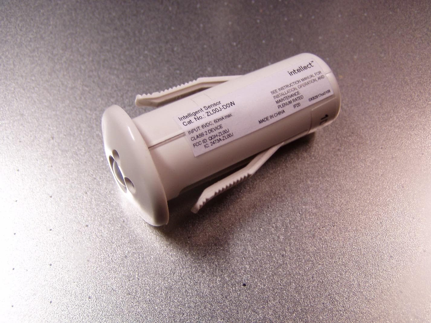
QGH-ZL00J
Apr 07, 2020ZL00J-D0W Intellect Sensor Head
Equipment Class
DTS - Digital Transmission System
QGH-ZBMG
Jan 02, 20200XB1803 Module
Equipment Class
DTS - Digital Transmission System