QGH-PVDIMO5C04-IDW, O5C20-MDW, 06C04-IDW, 06C20-MDW, V6C04-IDW, V6C20-MDW
Leviton Manufacturing Co., Inc.
Click to zoom
Application Details
- Equipment Class
- DTS - Digital Transmission System
- Date of Grant
- Apr 07, 2020
- Application Purpose
- Original Equipment
- Date of Application
- Apr 07, 2020
- Equipment Note
- O5C04-IDW, O5C20-MDW, 06C04-IDW, 06C20-MDW, V6C04-IDW, V6C20-MDW
- Frequency Range
- 2402.00000000 - 2480.00000000
- Country
- United States
Documents & Files
Document Text
Text extracted from the exhibit documents filed with the FCC. Open a document above to read the original.
Users Manual
INSTALLATION GUIDE PK-A3135-10-00-2B LINE VOLTAGE DIMMING ROOM CONTROLLERS CALIFORNIA TITLE 20 COMPLIANT Cat. Nos. OxC20-MDW/VxC20-MDW/ OxC04-IDW/VxC04-IDW Rating: 8A @ 120 VAC, 50/60 Hz ,1/4 Hp / Current Consumption: 60-30 mA Rating: 5A @ 277 VAC, 50/60 Hz, 1/3 Hp / Current Consumption: 60-30 mA Operating Temperature: 32 ̊ to 104 ̊F (0 ̊ to 40 ̊C) / Operating Humidity: 10 to 90%, non-condensing Compatible with 0-10V controlled 120-277VAC loads. Provolt TM WARNINGS AND CAUTIONS: IMPORTANT SAFEGUARDS When using electrical equipment, basic safety precautions should always be followed, including the following: a) READ AND FOLLOW ALL SAFETY INSTRUCTIONS. b) DO NOT use outdoors. c) DO NOT mount near gas or electric heaters. d) Equipment should be mounted in locations and at heights where it will not readily be subjected to tampering by unauthorized personnel. e) The use of accessory equipment not recommended by manufacturer may cause an unsafe condition. f) DO NOT use this equipment for other than the intended use. SAVE THESE INSTRUCTIONS TOOLS NEEDEDDESCRIPTION • Slotted/Phillips Screwdriver • Small Slotted Screwdriver • Wire stripper • Cutters The next generation of lighting control technology is here with the new Provolt™ Room Controller with Bluetooth ® Technology. This innovative device works using the Leviton Provolt™ app that can be easily downloaded to smartphones or tablets and paired to the Leviton Provolt™ Room Controller using Bluetooth ® technology. Provolt™ Room Controller devices give users point-to-point local control to automate lighting, bridging the gap between standard room controllers and whole-building automation systems. The Leviton Provolt™ app can be easily downloaded to mobile devices and is compatible with Android and iOS smartphones or tablets. The app is easy to use with simple, intuitive on-screen menu options to control a Provolt™ Room Controller. Wiring Diagram 1 (1-Zone units) Wiring Diagram 2 (2-Zone units) NOTES: • Both loads of the 2-Zone units MUST be fed from the same phase. • When installing Class 2 wiring use the provided tubing for insulation inside the junction box. To mount inside 4" octagon 2.125" deep ceiling electrical box (Fig. 1). • Dress line voltage wires to provide enough clearance in electrical box when device is installed. • Partially thread two #8-32 screws (not included) into the mounting holes of the electrical box. • Pull out the two coasters that align with the two screws. • Align room controller so that it fits between the mounting holes of the electrical box and insert over mounting screws. • Push in the two coasters that align with the two screws. • Tighten mounting screws firmly. To mount inside 4" square 1.5" deep ceiling electrical box with mud ring (Fig. 2). • Ensure that conduit/cable entry clamp is located in corner of electrical box. • Dress line voltage wires to provide enough clearance in electrical box when device is installed. • Install a two-gang mud ring (not included) on electrical box. • Partially thread the two #6-32 screws provided into the mounting holes of the electrical box. • Pull out the two coasters that align with the two screws. • Align room controller so that it fits between the mounting holes of the electrical box and insert over mounting screws. • Push in the two coasters that align with the two screws. • Tighten mounting screws firmly. The O5C20-MDW & O6C20-MDW Room Controllers are LINE-voltage multi-technology (PIR and Ultrasonic) sensors (Occupancy and Photocell) that automatically control lighting. The room controller is multiple sensors and technology working together to provide room lighting automatically and efficiently. Occupancy sensors turn the lights ON and keep them ON, will turn them OFF when room is vacant and delayed-off timer expires. Photocell detects natural light and dims room lighting up or down as needed for additional energy efficiency and circadian rhythm occupant comfort benefits. The V6C20-MDW LINE-voltage multi-technology Partial Off Room Controller monitors the space for vacancy. The lights can be turned ON manually by pressing the low-voltage/momentary toggle switch or PLVSW 1, 2, or 4 button switch. The sensor turns the lights OFF when vacancy is detected and the delayed-off time has expired. NOTE: Multiple PLVSW switches can be used with a single Provolt Room Controller. Multiple 2 and 4 button switches OR multiple 1 button or low voltage momentary or toggle switches. The combination of ultrasonic (doppler shift) motion detection which gives maximum sensitivity and infrared motion detection which gives higher false triggering immunity yields a sensor with excellent performance. The O5C04-IDW & O6C04-IDW Room Controllers are LINE-voltage infrared sensors that automatically control lighting. The room controller is multiple sensors working together to provide room lighting automatically and efficiently. Occupancy sensor turns the lights ON and keeps them ON, will turn them OFF when room is vacant and delayed-off timer expires. Photocell detects natural light and dims room lighting up or down as needed for additional energy efficiency and circadian rhythm occupant comfort benefits. The V6C04-IDW LINE-voltage infrared Partial Off Room Controller monitors the space for vacancy. The lights can be turned ON manually by pressing the low-voltage/momentary toggle switch or PLVSW 1, 2, or 4 button switch. The sensor turns the lights OFF when vacancy is detected and the delayed- off time has expired. NOTE: Multiple PLVSW switches can be used with a single Provolt Room Controller. Multiple 2 and 4 button switches OR multiple 1 button or low voltage momentary or toggle switches. Infrared motion detection gives higher false triggering immunity that yields a sensor with excellent performance. These sensors continually analyze and adjust to changing conditions and use the latest microprocessor-based technology which permits them to continually adjust and optimize their performance. PARTS INCLU…
Text truncated - open the document above for the full version.
External Photos
1 2 3 4 6 7 8 9 11 12 13 14 15 16 17 18 19 20 21 22 23 1 2 3 4 6 7 8 9 14 15 16 18 19 20 21 1 2 3 4 6 7 8 9 11 12 13 14 15 16 17 18 19 20 21 22 23 1 2 3 4 6 7 8 9 11 12 13 14 15 16 18 19 21 22 23 1 2 3 4 6 7 8 9 11 12 13 14 15 16 17 18 19 20 21 22 23 1 2 3 4 6 7 8 9 11 12 13 14 15 16 18 19 21 22 23
ID Label/Location Info
O5C04-IDW FCC and IC label. V6C20-MDW FCC-IC Label V6C04-IDW FCC-IC Label O6C20-MDW FCC-IC Label O6C04-IDW FCC-IC Label O5C20-MDW FCC-IC Label
Internal Photos
Front view Provolt logic board with radio Rear view Provolt logic board with radio
Operational Description
Leviton Manufacturing Co., Inc. 201 North Service Rd. Melville, NY 11747 tel 800 323-8920 fax 800 832-9538 www.leviton.com May 3, 2016 Antenna Info Johanson Technology 2450AT42A100E Ceramic Chip Antenna o Peak gain: 0 dBi typical (XZ-V) o Average gain: -1 dBi typical (XZ-V) o SMD Ceramic Chip Antenna, 2.4GHz – 2.5GHz, Typical: Case is SMD 43-1. Picture of ceramic chip antennas from Johanson Technology: To comply with FCC Part 15 Antenna requirement, the antenna is a printed circuit board surface mount device attached by solder that is not intended to be replaced in the field. Antenna location on PCB, physical: Y5 Antenna on PCB 2 Antenna location PCB layout: Y5Antenna layout location on PCB
RF Exposure Info
This report must not be used to claim product certification, approval, or endorsement by NVLAP, NIST, or any agency of the U.S. Government. This Report shall not be reproduced, except in full without written approval of the laboratory. EAR-Controlled Data - This document contains technical data whose export and reexport/retransfer is subject to control by the U.S. Department of Commerce under the Export Administration Act and the Export Administration Regulations. The Department of Commerce’s prior written approval may be required for the export or re- export/retransfer of such technical data to any foreign person, foreign entity or foreign organization whether in the United States or abroad. More: https://www.bis.doc.gov/index.php/forms-documents/regulations-docs/14-commerce-country-chart/fileT Leviton Mfg Co, Inc Provolt Line Voltage Dimming Room Controller FCC 2.1091:2019 Bluetooth Low Energy Report # LEVT0119 NVLAP Lab Code: 200630 CERTIFICATE OF EVALUATION 2018-09-14 Product compliance is the responsibility of the client; therefore, the tests and equipment modes of operation represented in this report were agreed upon by the client, prior to testing. The results of this test pertain only to the sample(s) tested. The specific description is noted in each of the individual sections of the test report supporting this certificate of test. This report reflects only those tests from the referenced standards shown in the certificate of test. It does not include inspection or verification of labels, identification, marking or user information. As indicated in the Statement of Work sent with the quotation, Element’s standard process is to always use the latest published version of the test methods even when earlier versions are cited in the test specification. Issuance of a purchase order was de facto acceptance of this approach. Otherwise, the client would have advised Element in writing of the specific version of the test methods they wanted applied to the subject testing Last Date of Evaluation: Tuesday, January 28, 2020 Leviton Mfg Co, Inc EUT: Provolt Line Voltage Dimming Room Controller RF Exposure Evaluation Standards Specification Method FCC 2.1091:2019 FCC 447498 D01 General RF Exposure Guidance v06 Results Method Clause Description Applied Results Comments 7.1 Maximum Permissible Exposure Yes Pass None Deviations From Evaluation Standards None Approved By: Donald Facteau, Process Architect Report No. LEVT0119EAR-Controlled Data2/9 REVISION HISTORY 2018.07.17 Revision Number Description Date (yyyy-mm-dd) Page Number 00 None Report No. LEVT0119EAR-Controlled Data3/9 ACCREDITATIONS AND AUTHORIZATIONS 2019.03.08 United States FCC - Designated by the FCC as a Telecommunications Certification Body (TCB). Certification chambers, Open Area Test Sites, and conducted measurement facilities are listed with the FCC. A2LA - Accredited by A2LA to ISO / IEC 17065 as a product certifier. This allows Element to certify transmitters to FCC and IC specifications. NVLAP - Each laboratory is accredited by NVLAP to ISO 17025 Canada ISED - Recognized by Innovation, Science and Economic Development Canada as a Certification Body (CB) and as a CAB for the acceptance of test data. European Union European Commission – Within Element, we have a EU Notified Body validated for the EMCD and RED Directives. Australia/New Zealand ACMA - Recognized by ACMA as a CAB for the acceptance of test data. Korea MSIT / RRA - Recognized by KCC’s RRA as a CAB for the acceptance of test data. Japan VCCI - Associate Member of the VCCI. Conducted and radiated measurement facilities are registered. Taiwan BSMI – Recognized by BSMI as a CAB for the acceptance of test data. NCC - Recognized by NCC as a CAB for the acceptance of test data. Singapore IDA – Recognized by IDA as a CAB for the acceptance of test data. Israel MOC – Recognized by MOC as a CAB for the acceptance of test data. Hong Kong OFCA – Recognized by OFCA as a CAB for the acceptance of test data. Vietnam MIC – Recognized by MIC as a CAB for the acceptance of test data. SCOPE For details on the Scopes of our Accreditations, please visit: https://www.nwemc.com/emc-testing-accreditations Report No. LEVT0119EAR-Controlled Data4/9 FACILITIES 2019.03.08 California Labs OC01-17 41 Tesla Irvine, CA 92618 (949) 861-8918 Minnesota Labs MN01-10 9349 W Broadway Ave. Brooklyn Park, MN 55445 (612)-638-5136 Oregon Labs EV01-12 6775 NE Evergreen Pkwy #400 Hillsboro, OR 97124 (503) 844-4066 Texas Labs TX01-09 3801 E Plano Pkwy Plano, TX 75074 (469) 304-5255 Washington Labs NC01-05 19201 120 th Ave NE Bothell, WA 98011 (425)984-6600 NVLAP NVLAP Lab Code: 200676-0 NVLAP Lab Code: 200881-0 NVLAP Lab Code: 200630-0 NVLAP Lab Code:201049-0 NVLAP Lab Code: 200629-0 Innovation, Science and Economic Development Canada 2834B-1, 2834B-3 2834E-1, 2834E-3 2834D-1 2834G-1 2834F-1 BSMI SL2-IN-E-1154R SL2-IN-E-1152R SL2-IN-E-1017 SL2-IN-E-1158R SL2-IN-E-1153R VCCI A-0029 A-0109 A-0108 A-0201 A-0110 Recognized Phase I CAB for ISED, ACMA, BSMI, IDA, KCC/RRA, MIC, MOC, NCC, OFCA US0158 US0175 US0017 US0191 US0157 Report No. LEVT0119EAR-Controlled Data5/9 PRODUCT DESCRIPTION 2018-07-17 Client and Equipment Under Evaluation Information Company Name: Leviton Mfg Co, Inc Address: 20497 SW Teton Avenue City, State, Zip: Tualatin, OR 97062 Evaluation Requested By: Stephen Miller EUT: Provolt Line Voltage Dimming Room Controllers Date of Evaluation: Tuesday, January 28, 2020 Information Provided by the Party Requesting the Evaluation Functional Description of the Equipment: Line Voltage Dimming Room Controller with a Bluetooth Low Energy radio and one antenna type. Objective: To demonstrate compliance with FCC requirements for RF exposure for 2.1091 mobile/fixed devices Report No. LEVT0119EAR-Controlled Data6/9 RF Exposure Condition 2018-07-17 The following RF Exposure conditions were used for the assessment documented in this report: Intended Use Mobile Location on Body (if applicable) NA How is the Device …
Text truncated - open the document above for the full version.
Test Report
This report must not be used to claim product certification, approval, or endorsement by NVLAP, NIST, or any agency of the federal government of the United States of America. This Report may only be duplicated in its entirety Leviton Manufacturing Company Provolt Line Voltage Dimming Room Controllers FCC 15.207:2016 FCC 15.247:2016 Bluetooth LE Radio Report # LEVT0119.2 NVLAP Lab Code: 200630-0 CERTIFICATE OF TEST 2017-1-25 2014-12-10 Product compliance is the responsibility of the client; therefore, the tests and equipment modes of operation represented in this report were agreed upon by the client, prior to testing. The results of this test pertain only to the sample(s) tested. The specific description is noted in each of the individual sections of the test report supporting this certificate of test. This report reflects only those tests from the referenced standards shown in the certificate of test. It does not include inspection or verification of labels, identification, marking or user information. Last Date of Test: January 5, 2016 Issue Date: January 28, 2020 Leviton Manufacturing Company Model: Provolt Line Voltage Dimming Room Controllers Radio Equipment Testing Standards Specification Method FCC 15.207:2016 ANSI C63.10:2013, KDB 558074 D01 v03r03 FCC 15.247:2016 Testing was performed to the version of the standard(s) in force at the date of testing. Since then, a newer version of the standard has been released. A comparison of the two versions of the standards has been made and the test results continue to show compliance to the latest version of the standards. Results Method Clause Test Description Applied Results Comments 6.2 AC Powerline Conducted Emissions Yes Pass 6.5, 6.6, 11.12.1, 11.13.2 Spurious Radiated Emissions Yes Pass 11.6 Duty Cycle Yes N/A Characterization of radio operation. 11.8.2 Occupied Bandwidth Yes Pass 11.9.2.2.4 Output Power Yes Pass 11.10.2 Power Spectral Density Yes Pass 11.11 Band Edge Compliance Yes Pass 11.11 Spurious Conducted Emissions Yes Pass Deviations From Test Standards None Approved By: Kyle Holgate, Operations Manager Report No. LEVT0119.2EAR-Controlled Data2/63 REVISION HISTORY REV 2014.10.14 Revision Number Description Date Page Number 00 None Report No. LEVT0119.2EAR-Controlled Data3/63 ACCREDITATIONS AND AUTHORIZATIONS REV 2016.3.22 United States FCC - Designated by the FCC as a Telecommunications Certification Body (TCB). Certification chambers, Open Area Test Sites, and conducted measurement facilities are listed with the FCC. A2LA - Accredited by A2LA to ISO / IEC 17065 as a product certifier. This allows Northwest EMC to certify transmitters to FCC and IC specifications. NVLAP - Each laboratory is accredited by NVLAP to ISO 17025 Canada IC - Recognized by Industry Canada as a Certification Body (CB). Certification chambers and Open Area Test Sites are filed with IC. European Union European Commission – Validated by the European Commission as a Notified Body under the R&TTE Directive. Australia/New Zealand ACMA - Recognized by ACMA as a CAB for the acceptance of test data. Korea MSIP / RRA - Recognized by KCC’s RRA as a CAB for the acceptance of test data. Japan VCCI - Associate Member of the VCCI. Conducted and radiated measurement facilities are registered. Taiwan BSMI – Recognized by BSMI as a CAB for the acceptance of test data. NCC - Recognized by NCC as a CAB for the acceptance of test data. Singapore IDA – Recognized by IDA as a CAB for the acceptance of test data. Israel MOC – Recognized by MOC as a CAB for the acceptance of test data. Hong Kong OFCA – Recognized by OFCA as a CAB for the acceptance of test data. Vietnam MIC – Recognized by MIC as a CAB for the acceptance of test data. SCOPE For details on the Scopes of our Accreditations, please visit: http://www.nwemc.com/accreditations/ http://gsi.nist.gov/global/docs/cabs/designations.html Report No. LEVT0119.2EAR-Controlled Data4/63 MEASUREMENT UNCERTAINTY TMU.2015.07.10 Measurement Uncertainty When a measurement is made, the result will be different from the true or theoretically correct value. The difference is the result of tolerances in the measurement system that cannot be completely eliminated. To the extent that technology allows us, it has been our aim to minimize this error. Measurement uncertainty is a statistical expression of measurement error qualified by a probability distribution. A measurement uncertainty estimation has been performed for each test per our internal quality document QM205.4.6. The estimation is used to compare the measured result with its "true" or theoretically correct value. The expanded measurement uncertainty (K=2) can be found included as part of the applicable test description page. Our measurement data meets or exceeds the measurement uncertainty requirements of the applicable specification; therefore, the test data can be compared directly to the specification limit to determine compliance. The calculations for estimating measurement uncertainty are based upon ETSI TR 100 028 (or CISPR 16-4-2 as applicable), and are available upon request. The following table represents the Measurement Uncertainty (MU) budgets for each of the tests that may be contained in this report. Test + MU - MU Frequency Accuracy (Hz) 0.0007% -0.0007% Amplitude Accuracy (dB) 1.2 dB -1.2 dB Conducted Power (dB) 0.3 dB -0.3 dB Radiated Power via Substitution (dB) 0.7 dB -0.7 dB Temperature (degrees C) 0.7°C -0.7°C Humidity (% RH) 2.5% RH -2.5% RH Voltage (AC) 1.0% -1.0% Voltage (DC) 0.7% -0.7% Field Strength (dB) 5.2 dB -5.2 dB AC Powerline Conducted Emissions (dB) 2.4 dB -2.4 dB Report No. LEVT0119.2EAR-Controlled Data5/63 FACILITIES REV 2015.2.19 California Labs OC01-13 41 Tesla Irvine, CA 92618 (949) 861-8918 Minnesota Labs MN01-08, MN10 9349 W Broadway Ave. Brooklyn Park, MN 55445 (612)-638-5136 New York Labs NY01-04 4939 Jordan Rd. Elbridge, NY 13060 (315) 554-8214 Oregon Labs EV01-12 22975 NW Evergreen Pkwy Hillsboro, OR 97124 (503) 844-4066 Texas Labs TX…
Text truncated - open the document above for the full version.
Test Setup Photos
AC POWERLINE CONDUCTED EMISSIONS WTD.2015.12.01 PSA-ESCI 2015.07.01, EmiR5 2015.11.06 AC POWERLINE CONDUCTED EMISSIONS WTD.2015.12.01 PSA-ESCI 2015.07.01, EmiR5 2015.11.06 AC POWERLINE CONDUCTED EMISSIONS WTD.2015.12.01 PSA-ESCI 2015.07.01, EmiR5 2015.11.06 AC POWERLINE CONDUCTED EMISSIONS WTD.2015.12.01 PSA-ESCI 2015.07.01, EmiR5 2015.11.06 photo Spurious FCC EV01 (1).JPG Spurious FCC EV01 (2).JPG SPURIOUS RADIATED EMISSIONS PSA-ESCI 2015.07.01 photo Spurious FCC EV01 (3).JPG Spurious FCC EV01 (4).JPG SPURIOUS RADIATED EMISSIONS PSA-ESCI 2015.07.01 photo Spurious FCC EV01 (5).JPG SPURIOUS RADIATED EMISSIONS PSA-ESCI 2015.07.01 XMit 2015.01.14 EV01 FCC 001.JPG EV01 FCC 002.JPG DIRECT CONNECT
Contact Information
Applicant
Frank Tse(Manager)
Test Firm
Element Materials TechnologyRenee Walker
Technical Specifications
| # | Rule Parts | Frequency Range | Power Output |
|---|---|---|---|
| 1 | 15C | 2.40 GHz - 2.48 GHz | 100.00 µW |
Other Applications from Leviton Manufacturing Co., Inc.

QGH-B167601
Jun 25, 2020Lumina Wall Dimmer and Wireless Load Control Dimmer
Equipment Class
DTS - Digital Transmission System
QGH-B167602
Jun 25, 2020Lumina RF Wall Switch and Wireless Load Controller
Equipment Class
DTS - Digital Transmission System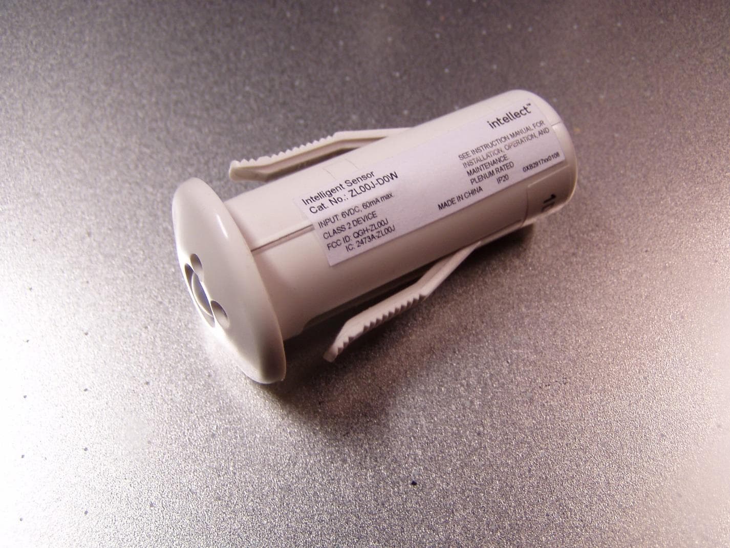
QGH-ZL00J
Apr 07, 2020ZL00J-D0W Intellect Sensor Head
Equipment Class
DTS - Digital Transmission System
QGH-ZBMG
Jan 02, 20200XB1803 Module
Equipment Class
DTS - Digital Transmission System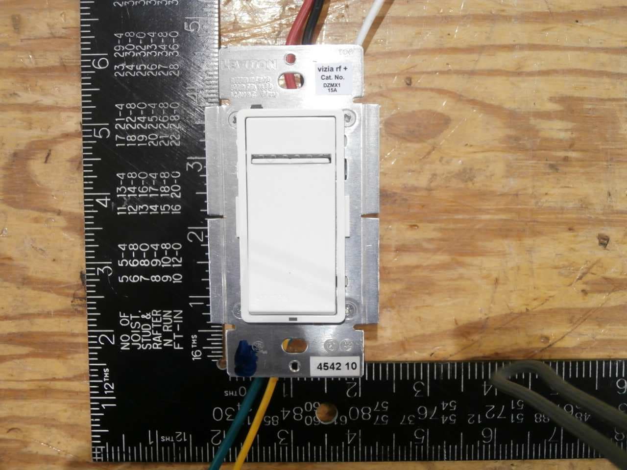
QGH-VRMX1
Dec 04, 2014Light Dimmer
Equipment Class
DXT - Part 15 Low Power Transceiver, Rx Verified