QGH-B167602Lumina RF Wall Switch and Wireless Load Controller
Leviton Manufacturing Co., Inc.
Click to zoom
Application Details
- Equipment Class
- DTS - Digital Transmission System
- Date of Grant
- Jun 25, 2020
- Application Purpose
- Original Equipment
- Date of Application
- Jun 24, 2020
- Equipment Note
- Lumina RF Wall Switch and Wireless Load Controller
- Frequency Range
- 2405.00000000 - 2475.00000000
- Country
- United States
Documents & Files
Document Text
Text extracted from the exhibit documents filed with the FCC. Open a document above to read the original.
Users Manual
CAUTIONS • Use this device with copper or copper clad wire only. • For indoor applications only. • SAVE THESE INSTRUCTIONS. 0-10 VDC Ballast/LED Driver Black Blue Black Hot (Black) Gray Neutral (White) Line Electrical Box White White Sleeve Violet Connectors Green Ground RF Wireless Load Control 20A Switching Relay, RF Wireless Load Control 0-10V Dimmer and RF Wireless Load Control 800W Dimmer Cat. Nos. LU20S, LU107 and LU04P INSTALLATION INSTRUCTIONS ENGLISH PK-A3314-10-00-2A-X3 Before Installation • Install to outside or inside of junction box or outside of luminaire. • If mounted inside, a plastic cover must be used (metal will limit the RF signal). • LU107 uses 0-10Vdc low voltage control wires which may be installed as Class 1 or Class 2. NOTE (LU107): 0-10V Control Wiring - Connect the violet wire to the + 0-10V line and the gray wire to the 0-10V common using Class 1 or Class 2 wiring methods as indicated in these instructions, ballast/fixture/driver instructions or ballast/fixture/ driver label markings. Observe all requirements of any authority having jurisdiction with respect to wire type, sleeving, isolation methods, and the like. WARNINGS • TO AVOID FIRE, SHOCK, OR DEATH; TURN OFF POWER AT CIRCUIT BREAKER OR FUSE AND TEST THAT POWER IS OFF BEFORE WIRING! • T o be installed and/or used in accordance with appropriate electrical codes and regulations. • If you are unsure about any part of these instructions, consult an electrician. PK-A3314-10-00-2A-X3 © 2019 Leviton Mfg. Co., Inc. 2.Strip wires 3/4 in and connect as per wiring diagram. Ensure wires are firmly attached and there is no exposed copper. a. LU107 Wiring Diagram Product Description The Leviton Lumina ® RF Load Controllers are components within a Lumina RF Standalone Platform and must be paired with a Lumina ® RF Room Controller. The LU20S contains a power supply and a 20A relay to provide remote control switching of lighting, motor loads, and plug load control. The LU107 Load Controller is designed for 0-10V dimming loads and to be used for individual or groups of luminaires up to 10A. The LU04P supports individual or groups of luminaires with phase cut dimming of loads up to 800W. Lumina ® RF devices communicate with each other via 2.4 GHz radio frequency. Each wireless device in the system is designed to act as a repeater and will re- transmit the RF signal from one device to another to ensure the signal is received by its intended device. There are several basic system components: • Lumina ® RF SA App: Bluetooth™-enabled, wirelessly communicates with the Room Controller to configure the system. • Lumina ® RF Room Controllers: these are used to coordinate and control all of the wireless devices in a specified space or room. It manages all energy management functionality both as required by code and as desired by the user. Contains a Bluetooth radio to connect to mobile device with the Lumina ® RF SA App. Provides dimming, switching, and scene control. • Lumina ® RF Load Controllers: controls individual or groups of fixtures or receptacles for plug load control. Allows for wireless dimming and ON/OFF control of fixtures or receptacles. • Lumina ® RF Switches and Dimmers: provide ON/OFF, 0-10V dimming, or Phase Cut dimming of luminaires. Adds 3-way control of luminaires for spaces with multiple entries. • Lumina ® RF Occupancy Sensors: adds occupancy or vacancy sensing to the system. • Lumina ® RF Photocell: adds daylight harvesting to the system. NOTE: Each room requires a Room Controller. c. LU04P Wiring Diagram Black Load Hot (Black)Black Line 120 V AC, 60Hz Neutral (White) Blue White White Green Ground 4. Using the Lumina ® RF SA App, connect to room controller to set up device and configure your system. • From Factory Default, the LU107 and LU20S are in auto join mode. • For the LU04P, press and hold the button for 7 seconds, then release the button. The locator light will blink amber. Press and release the button without holding. The locator light will flash green and the device will be in join mode. • When the LU04P is added to the system by the room controller, the locator light will blink green 3 times. If it fails to be added, the locator light will blink red 3 times WARNING: TO AVOID FIRE, SHOCK, OR DEATH; TURN OFF POWER at circuit breaker or fuse and test that power is off before wiring! 1. Mount the Load Control device to junction box or luminaire through 1/2 in hole or knockout and secure with provided locknut. ATTENTION: For LU04P, ensure the thermal pad is in contact with the metal junction box. LU04P is not to be installed in enclosed junction box. Installation b. LU20S Wiring Diagram Line 120/277VAC, 50/60Hz. Blue White Hot (Black) Black Neutral (White) White Load Green Ground 3. Restore power at circuit breaker or fuse. LU04P thermal pad The Load Control device can be turned ON and OFF automatically when the room controller is paired with a Lumina RF Occupancy Sensor and/or photocell for daylighting. When configured with an occupancy sensor, the Load Control device can be programmed for Auto ON (turns ON when occupancy is detected) or Manual ON (turns ON when a Room Controller or switch is engaged). The Load Controllers will turn OFF when occupancy is no longer detected. Operation ® © 2019 Leviton Mfg. Co., Inc. Statement Caution Changes or modifications not expressly approved by Leviton Manufacturing Co., could void the user’s authority to operate the equipment. FCC Statement: This device complies with Part 15 of the FCC Rules. Operation is subject to the following two conditions: (1) This device may not cause harmful interference, and (2) This device must accept any interference received, including interference that may cause undesired operation. This equipment has been tested and found to comply with the limits for a Class B digital device, pursuant to part 15 of the FCC Rules. These limits are designed to provide reasonable protection against harmful interference in a residential installation. …
Text truncated - open the document above for the full version.
Users Manual
MISES EN GARDE • Les produits décrits aux présentes ne doivent être utilisés qu’avec du fil de cuivre ou plaqué cuivre. • Les produits décrits aux présentes sont pour l’intérieur seulement. • CONSERVER LES PRÉSENTES DIRECTIVES. Ballast/régulateur de DEL de 0-10 V c.c. Noir Bleu Noir Actif (noir) Gris Neutre (blanc) Line Electrical Box Blanc Blanc Manchon Violet Connecteurs Terre (vert) Relais de commutation de 20 A, et gradateurs de 0 à 10 V/800 W sans fil (RF) pour la commande de charges N os de cat. LU20S, LU107 et LU04P INSTALLATION FRANÇAIS PK-A3314-10-05-2A-X3 Préparation • Les produits décrits aux présentes doivent être installés à l’extérieur d’un luminaire ou à l’intérieur d’une boîte de raccordement. • Dans ce dernier cas, il faut employer un couvercle de plastique (le métal nuit aux signaux RF). • Le modèle LU107 emploie des fils de commande à basse tension de 0-10 V c.c. qui peuvent être raccordés comme étant de classe 1 ou 2. REMARQUE RELATIVE AU MODÈLE LU107 : pour le câblage de commande de 0-10 V, il faut raccorder le fil violet au fil de ligne et le fil gris au fil commun en employant des méthodes de classe 2, telles que décrites aux présentes, dans les directives des ballasts/luminaires/régulateurs employés ou encore sur les étiquettes de ces derniers. Il faut en outre respecter les exigences de toutes les autorités en la matière en ce qui concerne les types de fil à utiliser, les manchons à privilégier, les méthodes d’isolation, etc. AVERTISSEMENTS • POUR ÉVITER LES RISQUES D’INCENDIE DE DÉCHARGE OU D’ÉLECTROCUTION COUPER LE COURANT AU FUSIBLE OU AU DISJONCTEUR ET S’ASSURER QUE LE CIRCUIT EST BIEN COUPÉ AVANT DE PROCÉDER AU CÂBLAGE! • Les produits décrits aux présentes doivent être installés et utilisés conformément aux codes de l’électricité en vigueur. • À défaut de bien comprendre les présentes directives, en tout ou en partie, on doit faire appel à un électricien. PK-A3314-10-05-2A-X3© 2019 Leviton Mfg. Co., Inc. 2.Dénuder les fils sur 3/4 po (1,9 cm) et les raccorder conformément au schéma de câblage. S’assurer que les fils sont solidement reliés et qu’aucune section de cuivre n’est exposée. a. Schéma de câblage du modèle LU107 Description des produits Les contrôleurs de charges Lumina MD RF de Leviton sont des composants d’une plateforme autonome qui doivent être associés à un contrôleur de pièce de la même gamme. Le modèle LU20S contient un bloc d’alimentation et un relais de 20 A pour assurer la commande à distance de charges d’éclairage, motorisées et enfichées. Le modèle LU107 est quant à lui conçu pour régler une ou plusieurs charges de 0 à 10 V (maximum de 10 A). Finalement, le modèle LU04P peut commander un ou plusieurs luminaires à coupure de phase d’une puissance pouvant atteindre 800 W. Les dispositifs sans fil Lumina MD RF communiquent entre eux via une fréquence radio de 2,4 GHz. Chacun est conçu pour agir en tant que répéteur qui retransmet les signaux RF pour faire en sorte qu’ils soient bien reçus par la commande visée. Le système comprend plusieurs composants de base : • L’appli Lumina MD RF SA dotée de la technologie Bluetooth MC , elle communique sans fil avec le contrôleur de pièce pour configurer le système. • Un contrôleur de pièce Lumina MD RF : utilisé pour coordonner et commander tous les dispositifs sans fil d’une pièce ou d’un espace donné. Ces contrôleurs permettent de se conformer aux exigences des utilisateurs et des codes locaux en matière de gestion de l’énergie. Ils contiennent une radio Bluetooth qui leur permet de communiquer avec un appareil mobile via l’appli Lumina MD RF SA. Ils peuvent ainsi régler ou commuter des luminaires, ou encore créer des ambiances les utilisant. • Des contrôleurs de charges Lumina MD RF : commandent un ou plusieurs luminaires ou prises dans lesquelles divers appareils peuvent être enfichés. Ces contrôleurs sans fil permettent de commuter, d’intensifier ou de tamiser l’éclairage. • Des interrupteurs et des gradateurs Lumina MD RF : assurent la commutation et la gradation de 0 à 10 V ou à coupure de phase de divers luminaires. Ces dispositifs permettent en outre la commande des mêmes charges depuis plusieurs entrées. • Des détecteurs d’occupation Lumina MD RF : ajoutent des fonctions supplémentaires aux systèmes. • Une photocellule Lumina MD RF : permet d’exploiter la lumière ambiante. REMARQUE : il doit y avoir un contrôleur de pièce dans chaque aire à commander. c. Schéma de câblage du modèle LU04P Noir Charge Actif (Noir)Noir Ligne 120 V c.a., 60 Hz Neutre (blanc) Bleu Blanc Blanc Terre (vert) 4. Au moyen de l’appli Lumina MD RF SA, se connecter au contrôleur de pièce afin de paramétrer les dispositifs et de configurer le système. • Par défaut, les modèles LU107 et LU20S sont en mode d’association automatique. • Dans le cas du modèle LU04P, il faut enfoncer le bouton pendant sept secondes, puis le relâcher. Le témoin de localisation clignotera en ambre. Appuyer brièvement sur le bouton. Le témoin devrait clignoter en vert; le dispositif est alors en mode d’association. • Quand le modèle LU04P aura été ajouté au système par le contrôleur de pièce, le témoin clignotera en vert trois fois. Si l’association n’a pas fonctionné, il clignotera plutôt trois fois en rouge. AVERTISSEMENT : POUR ÉVITER LES RISQUES D’INCENDIE, DE DÉCHARGE OU D’ÉLECTROCUTION, COUPER LE COURANT au fusible ou au disjoncteur et s’assurer que le circuit est bien hors tension avant de procéder au câblage! 1. Fixer le dispositif de commande au luminaire ou à la boîte via le trou ou la débouchure de 1/2 po (1,3 cm), en l’assujettissant au moyen du contre-écrou fourni. ATTENTION : il faut s’assurer que l’écran thermique du modèle LU04P reste en contact avec la paroi métallique de la boîte. Ce modèle ne peut être installé dans une boîte fermée. Installation b. Schéma de câblage du modèle LU20S Ligne 120/277 V c.a., 50/60 Hz Bleu Blanc Actif (noir) Noir Neutre (blanc) Blanc Charge Terre (vert) 3. Rétablir le courant au fusible ou au disjonct…
Text truncated - open the document above for the full version.
Users Manual
• Installs into any single gang device back-box. • Supports Multi-gang installations. • Requires Decora ® faceplate, sold separately WARNINGS • TO AVOID FIRE, SHOCK, OR DEATH; TURN OFF POWER AT CIRCUIT BREAKER OR FUSE AND TEST THAT POWER IS OFF BEFORE WIRING! • To be installed and/or used in accordance with appropriate electrical codes and regulations. • If you are unsure about any part of these instructions, consult an electrician. CAUTIONS • Use this device with copper or copper clad wire only. • For indoor applications only. • Save these instructions. DI-000-ZS10S-02B-X1© 2019 Leviton Mfg. Co., Inc. WARNING: TO AVOID FIRE, SHOCK, OR DEATH; TURN OFF POWER at circuit breaker or fuse and test that power is off before wiring! 1. Connect as per wiring diagram. Before Installation Installation 2. Attach to wall box. 3. Restore power and test ON/OFF operation. LED locator light should be ON when switch power is turned OFF. RF Wall Switch Cat. No. ZS10S Ratings: 120-277VAC, 50/60Hz. INSTALLATION AND QUICK START SHEET ENGLISH DI-000-ZS10S-02B-X1 Line 120/277VAC, 50/60Hz. Blue White Hot (Black) Black Neutral (White) White Load Green Ground To release, push sides.Line up and press in to attach. 4. If desired, change switch color. 5. Install Decora faceplate. White Blue Green Black Load Neutral Line (Hot) Ground DI-000-ZS10S-02B-X1© 2019 Leviton Mfg. Co., Inc. SPECIFICATIONS Catalog No.ZS10S-D0Z Input Voltage/Frequency120-277VAC, 50/60Hz. Input Current 120V Standby: 0.2W Max: 0.5W+Load Current 277V Standby: 0.3W Max: 0.6W+Load Current Load Ratings LED, CFL, Electronic Ballast @ 120V10A LED, CFL, Electronic Ballast @ 277V10A Magnetic Ballast @ 120V10A Magnetic Ballast @ 277V10A Resistive, Tungsten @ 120V6.67A Resistive, Tungsten @ 277V6.67A Motor @ 120V1/4Hp (FLA 5.8A) Motor @ 277V1/3Hp (FLA 3.0A) IP RatingIP10 Network Connections IEEE 802.15.4, 2.4Ghz, wireless, mesh network up to 75' range between device Operating Temperature0°C - 40°C (32°F - 104°F) Storage Temperature-40°C to 85°C UL Pollution Degree2 UL Impulse Voltage6000V FCC COMPLIANCE STATEMENT: FCC ID: QGH-B167602 The enclosed device complies with Part 15 of the FCC Rules. Operation is subject to the following two conditions: (i.) This device may not cause harmful interference (ii.) This device must accept any interference received, including interference that may cause undesired operation. Any changes or modifications not expressly approved by Leviton could void the user’s authority to operate this equipment. This equipment has been tested and found to comply with the limits for a Class B digital device, pursuant to part 15 of the FCC Rules. These limits are designed to provide reasonable protection against harmful interference in a residential installation. This equipment generates uses and can radiate radio frequency energy and, if not installed and used in accordance with the instructions, may cause harmful interference to radio communications. However, there is no guarantee that interference will not occur in a particular installation. If this equipment does cause harmful interference to radio or television reception, which can be determined by turning the equipment off and on, the user is encouraged to try to correct the interference by one or more of the following measures: • Reorient or relocate the receiving antenna. • Increase the separation between the equipment and receiver. • Connect the equipment into an outlet on a circuit different from that to which the receiver is connected. • Consult the dealer or an experienced radio/TV technician for help. LIMITED 2 YEAR WARRANTY AND EXCLUSIONS Leviton warrants to the original consumer purchaser and not for the benefit of anyone else that this product at the time of its sale by Leviton is free of defects in materials and workmanship under normal and proper use for two years from the purchase date. Leviton’s only obligation is to correct such defects by repair or replacement, at its option. For details visit www.leviton.com or call 1-800-824-3005. This warranty excludes and there is disclaimed liability for labor for removal of this product or reinstallation. This warranty is void if this product is installed improperly or in an improper environment, overloaded, misused, opened, abused, or altered in any manner, or is not used under normal operating conditions or not in accordance with any labels or instructions. There are no other or implied warranties of any kind, including merchantability and fitness for a particular purpose, but if any implied warranty is required by the applicable jurisdiction, the duration of any such implied warranty, including merchantability and fitness for a particular purpose, is limited to two years. Leviton is not liable for incidental, indirect, special, or consequential damages, including without limitation, damage to, or loss of use of, any equipment, lost sales or profits or delay or failure to perform this warranty obligation. The remedies provided herein are the exclusive remedies under this warranty, whether based on contract, tort or otherwise. Installation (cont'd)Installation (cont'd) Configuration and Programming • Control functionality, LED Behavior, and user interaction can be adjusted based on the features of your system. Please refer to your system documentation for details. • Enrollment – Out of the box, the device is in Auto Join mode and is always active and attempting to join an open network. If you need to add your device to a network and it is not in auto join mode, reset to factory default and it will start searching for a network. o Locator LED will blink GREEN slowly while looking for an open network. • Factory Default – resets device to out of the box state o Push top or bottom of paddle for approximately 20 seconds until the locator LED flashes AMBER the second time. o Release paddle. o LEDs will alternate between green/amber while device is resetting, and turn off when complete. o When complete, device will reboot then revert to…
Text truncated - open the document above for the full version.
Users Manual
• Le produit visé aux présentes peut être installé dans n’importe quelle boîte murale pour un dispositif. • Il peut faire partie d’installations groupées. • Il requiert une plaque Decora MD (vendue séparément). AVERTISSEMENTS • POUR ÉVITER LES RISQUES D’INCENDIE, DE DÉCHARGE OU D’ÉLECTROCUTION, COUPER LE COURANT AU FUSIBLE OU AU DISJONCTEUR ET S’ASSURER QUE LE CIRCUIT EST BIEN COUPÉ AVANT DE PROCÉDER AU CÂBLAGE. • Le produit visé aux présentes doit être installé et utilisé conformément aux codes de l’électricité en vigueur. • À défaut de bien comprendre les présentes directives, en tout ou en partie, on doit faire appel à un électricien. MISES EN GARDE • Le produit visé aux présentes ne doit être utilisé qu’avec du fil de cuivre ou plaqué cuivre. • Le produit visé aux présentes est pour l’intérieur seulement. • Conserver les présentes directives. DI-000-ZS10S-52B-X1© 2019 Leviton Mfg. Co., Inc. AVERTISSEMENT : POUR ÉVITER LES RISQUES D’INCENDIE, DE DÉCHARGE OU D’ÉLECTROCUTION, COUPER LE COURANT au fusible ou au disjoncteur et s’assurer que le circuit est bien coupé avant de procéder à l’installation. 1. Raccorder les fils conformément au schéma de câblage Préparation Installation 2. Fixer le dispositif à la boîte murale. 3. Rétablir l’alimentation et vérifier les fonctions de commutation du dispositif. Le témoin de localisation devrait s’allumer quand les charges sont mises hors tension. Interrupteur RF No de cat. ZS10S Valeurs nominales : 120/277 V c.a., 50/60 Hz. FEUILLET D’INSTALLATION ET DE DÉMARRAGE RAPIDE FRANÇAIS DI-000-ZS10S-52B-X1 Ligne 120/277 V c.a., 50/60 Hz Bleu Blanc Actif (noir) Noir Neutre (blanc) Blanc Charge Terre (vert) Appuyer sur les côtés pour dégagerAligner la touche et serrer les languettes latérales 4. Changer la couleur du dispositif au besoin 5. Poser une plaque Decora. Blanc Bleu Vert Noir Charge Neutre Ligne (actif) Terre DI-000-ZS10S-52B-X1© 2019 Leviton Mfg. Co., Inc. FICHE TECHNIQUE No de catalogueZS10S-D0Z Tension/fréquence d’entrée120-277 V c.a., 50/60 Hz. Courant d’entrée 120 V Au repos : 0,2 W. Max : 0,5 W + courant de charge 277 V Au repos : 0,3 W. Max : 0,6 W + courant de charge Charges nominales DEL, LFC et ballasts électroniques à 120 V10 A DEL, LFC et ballasts électroniques à 277 V10 A Ballasts magnétiques à 120 V10 A Ballasts magnétiques à 277 V10 A Charges résistives au tungstène à 120 V6,67 A Charges résistives au tungstène à 277 V6,67 A Moteurs à 120 V1/4 ch (5,8 APC) Moteurs à 277 V1/3 ch (3,0 APC) Cote d’étanchéitéIP10 Connexions réseau IEEE 802.15.4, 2,4 GHz, réseau maillé sans fil avec des distances maximales de 75 pi (22,9 m) entre dispositifs Température de fonctionnement0 à 40 °C (32 à 104 °F) Température de rangement-40 à 85 °C Niveau de pollution UL2 Impulsions de tension UL6 000 V Installation (suite) Configuration et programmation • Les fonctions, le comportement des témoins et l’interface utilisateur peuvent être réglés suivant les caractéristiques du système en place. Se reporter à la documentation relative à ce dernier pour en savoir plus • Enregistrement — par défaut, le dispositif est en mode d’intégration automatique, tentant activement de s’inclure dans un réseau ouvert. Si ce mode n’est pas activé, il suffit de rétablir les valeurs par défaut du dispositif pour qu’il se remette à chercher o Le témoin de localisation clignote lentement en vert quand le dispositif cherche un réseau • Rétablissement des valeurs par défaut o Appuyer sur la partie supérieure de la bascule pendant environ 20 secondes, jusqu’à ce que le témoin de localisation clignote une deuxième fois en AMBRE. o Relâcher la bascule o Le témoin passe du vert au ambre pendant que le dispositif se réinitialise, puis s’éteint une fois l’opération complétée. o Le dispositif réinitialisé revient en mode d’intégration automatique, cherchant un réseau ouvert. Le témoin de localisation clignote lentement en vert quand le dispositif cherche un réseau. • Vérification d’état o Appuyer sur la partie supérieure de la bascule pendant cinq secondes, jusqu’à ce que le témoin de localisation clignote une fois en AMBRE. o Relâcher la bascule. o Le témoin de localisation clignotera pour indiquer l’état du dispositif : un clignotement ROUGE pour indiquer qu’il n’a pas été configuré; trois clignotements VERTS pour indiquer qu’il est connecté au réseau. • REMARQUE : si on enfonce la partie supérieure ou inférieure de la bascule pendant 25 secondes ou plus, le dispositif sort du mode de programmation et revient en mode de fonctionnement normal. Le cas échéant, le témoin de localisation clignotera une troisième fois en AMBRE TÉMOIN DE LOCALISATION – allumé quand les charges sont hors tension pour pouvoir repérer la commande BAS DE LA BASCULE – mise hors tension PROGRAMMATION Appui sur la partie supérieure ou inférieure de la bascule HAUT DE LA BASCULE – mise sous tension 6. Enregistrer le dispositif. Il est possible de programmer diverses fonctions, comme l’activation d’une ambiance de présentation au toucher de la partie supérieure de la bascule, par exemple. VOISINAGE ET EXPOSITION AUX RADIOFRÉQUENCES : Afin de se conformer aux exigences de la FCC et de respecter les seuils d’exposition aux radiofréquences prescrits par l’ISDE pour le grand public (environnements non contrôlés), le dispositif décrit aux présentes devrait être installé et utilisé à une distance minimale de 7,9 po (20 cm) de toute personne. Il ne doit être ni installé ni utilisé près d’autres antennes ou transmetteurs. DÉCLARATION DE CONFORMITÉ AUX NORMES D’INDUSTRIE CANADA : IC: 2473A-B167602 Ce produit est conforme aux exigences de la partie 15 des règlements de la FCC ainsi qu’aux cahiers des charges sur les normes radioélectriques d’ISDE pour les produits exempts de licence. Il peut être utilisé à condition qu’il (1) ne cause aucun brouillage préjudiciable et (2) ne soit pas affecté par les interférences d’autres dispositifs susceptibles notamment d’en perturber le fonctionnement. Toute modification apportée sans…
Text truncated - open the document above for the full version.
Cover Letter(s)
Frank Tse Director Codes Standards & Compliance Leviton Manufacturing Co., Inc. 201 North Service Road Melville, NY 11747 T: (631) 812-6437 www.leviton.com March 6, 2020 Cover Letter for FCC Application Please grant FCC certification for the Lumina RF Wall Switch family as described below. These 2 products utilize the 2.4GHz Zigbee protocol to work with other Zigbee products networked to the wall station. All models share same power PCB B1677 and logic PCB B1676 with different assembly variants to support functions as required. Each wall station utilizes a 2.4 GHz Zigbee radio that is integrated into the logic board B1676. Assembly differences of B1676 are as below: - There is no difference in radio MCU or components or antenna tuning values in all variants. - Variant D22 is same as used for variant D02 except only one switch. The power board B1677 for each wall station differs on the input voltage range that it is compatible. Variant D01 supports 120-277VAC. Preliminary testing on all variations of power and logic boards demonstrated that the RF specifications and performance are similar across all models and can be considered for a family approval under a single FCC ID for FCC. The table below shows the features for each model. Product ID Configuration Logic PCB Power PCB FCC ID# Model# / Cat# Description Radio 0-10 Vdc Dimming Switch PCB Variant Assembly Difference PCB Variant Input Voltage Loads Relay Rating QGH-B167602 ZS10S-D0Z Lumina 0-10VDC RF Wall Dimmer Zigbee No Yes B1676 D02 -- B1677 D01 120- 277VAC 5A Electronic 5A Fluorescent 10A Tungsten 5A/ 10A LU20S-DNW Lumina RF Wireless Load Control 0-10V Dimmer D22 D02 with only one switch Sincerely, Frank Tse
External Photos
FCC ID: QGH-B167602 IC:2473A-B167602 Page 1 of 3 External Photos FCC ID: QGH-B167602 IC: 2473A-B167602 FCC ID: QGH-B167602 IC:2473A-B167602 Page 2 of 3 FCC ID: QGH-B167602 IC:2473A-B167602 Page 3 of 3
ID Label/Location Info
Photos only for label placemen t purposes, refer to following pa ges for label drawings B B B NOTES (UNLESS OTHERWISE SPECIFIED): 1. MATERIAL AND DIMENSIONS SPECIFIED ON DRAWING OXB5300-D01. 2. PRINT BLACK CHARACTERS AND GRAPHICS ON WHITE BACKGROUND PER ARTWORK ORB5301-D01revB.ai (FOR PURCHASED, "xx" IN PART NO. = 89) OR .jpg (FOR SELF-PRINT, "xx" IN PART NO. = 00). GRAPHICS SHOWN FOR ILLUSTRATION PURPOSES ONLY. LEVITON PART NO.: 0XB5301xx0101 ASSEMBLED IN MEXICO - FOR FUTURE USE - LEVITON PART NO.: 0XB5301xx0108 MADE IN CHINA LEVITON PART NO.: 0XB5301xx0148 ASSEMBLED IN USA - FOR FUTURE USE - B PROJECT NO. PROJ-03163 TITLE: ORB5301-D01 ALL PRINTED COPIES ARE UNCONTROLLED STATUS: DWG NO. REV SIZE A UNLESS OTHERWISE SPECIFIED: DO NOT SCALE DRAWING. ALL DIMENSIONS ARE IN MILLIMETERS. ALL ANGLES ARE IN DEGREES. The information in this document is the exclusive PROPRIETARY property of LEVITON MFG. CO., INC. It is disclosed with the understanding that acceptance or review by the recipient constitutes an undertaking by the recipient: (1) to hold this information in strict confidence. (2) not to disclose, duplicate, copy, or use the information, in whole or in part, for any purpose other than that for which disclosed. DWN BY CHK BY TOLERANCES THIRD ANGLE PROJECTION Production Release B RJ09/22/2017 12/14/2018NR SHEET 1 OF 1SCALE:2:1 LABEL PROD ID 802.15.4 WALL SWITCH 12/14/2018NR MFG ENGRG YA12/14/2018 REV.DATE ECO NUMBER APVD 06/10/2019 RJRJ ECR18680 CHGD B 1/2° .XX .XXX ± ± INCH .01 .005 ANGLES: ± .X .XX METRIC .2 mm .10 mm ± ± Copyright 2010. Unpublished. All Rights Reserved. A RJYA 12/14/2018 ECR17502 - -- - - - -- - - - -- - - NOTES (UNLESS OTHERWISE SPECIFIED): 1. USE ARTWORK MODEL ORB7617-M01. 2. GRAPHICS SHOWN FOR ILLUSTRATION PURPOSES ONLY. 3. GRAPHICS TO BE LASER ENGRAVED IN LASER PRINTING MACHINE USING PARAMETERS IN TABLE BELOW. THIS SETUP WILL ETCH THE GRAPHICS ON THE PLASTIC AT THE PROPER COLOR TONE. (parameters TBD during Eng Run) PROJECT NO. PROJ-03357 TITLE: ORB7617-D01 ALL PRINTED COPIES ARE UNCONTROLLED STATUS: DWG NO. REV SIZE A UNLESS OTHERWISE SPECIFIED: DO NOT SCALE DRAWING. ALL DIMENSIONS ARE IN MILLIMETERS. ALL ANGLES ARE IN DEGREES. The information in this document is the exclusive PROPRIETARY property of LEVITON MFG. CO., INC. It is disclosed with the understanding that acceptance or review by the recipient constitutes an undertaking by the recipient: (1) to hold this information in strict confidence. (2) not to disclose, duplicate, copy, or use the information, in whole or in part, for any purpose other than that for which disclosed. DWN BY CHK BY TOLERANCES THIRD ANGLE PROJECTION In Work 1 KQ01/15/2019 -- SHEET 1 OF 1SCALE:2:1 ART - LASER ETCH LU20S LUMINA RF ZONE CONTROL -- MFG ENGRG -- REV.DATE ECO NUMBER APVD - -- - CHGD 1 1/2° .XX .XXX ± ± INCH .01 .005 ANGLES: ± .X .XX METRIC .2 mm .10 mm ± ± Copyright 2010. Unpublished. All Rights Reserved. - -- - - - -- - - - -- - - - -- - -
Internal Photos
FCC ID: QGH-B167602 IC:2473A-B167602 Page 1 of 9 Internal Photos FCC ID: QGH-B167602 IC: 2473A-B167602 Logic Board B1676 Logic Board contains the Radio IC and the antenna on bottom side of PCB Top Side FCC ID: QGH-B167602 IC:2473A-B167602 Page 2 of 9 Bottom Side FCC ID: QGH-B167602 IC:2473A-B167602 Page 3 of 9 Power Board B1677 Same for all three variants: ZS10S-D0Z, LU20S-DNW Top Side FCC ID: QGH-B167602 IC:2473A-B167602 Page 4 of 9 Bottom Side FCC ID: QGH-B167602 IC:2473A-B167602 Page 5 of 9 Components ZS10S-D0Z FCC ID: QGH-B167602 IC:2473A-B167602 Page 6 of 9 FCC ID: QGH-B167602 IC:2473A-B167602 Page 7 of 9 Components LU20S FCC ID: QGH-B167602 IC:2473A-B167602 Page 8 of 9 FCC ID: QGH-B167602 IC:2473A-B167602 Page 9 of 9
Operational Description
NOTES: SINGLE SOURCE: ALL ALTERNATES MUST HAVE ENGINEERING APPROVAL1. SEE FOLLOWING PAGES FOR PURCHASING INFO FROM DATA SHEET2. ITEM MUST BE ROHS COMPLIANT3. MANUFACTURING PART NUMBER EXPLANATION: SEE MANUFACTURER DATA SHEET FOR DETAILS NOTE: As of 09/23/2013 all new parts created to unified P/N system MANUFACTURER NAMEMANUFACTURER PART NUMBER JOHANSON TECHNOLOGY2450AT18D0100E LEVITON PART NUMBER (Global) 0XB1347890000…
Text truncated - open the document above for the full version.
Contact Information
Applicant
Frank Tse(Manager)
Technical Contact
Leviton Manufacturing Co., Inc.Frank Tse
201 North Service Road · Melville · United States
Test Firm
Laird Connectivity LLCAdam Alger
Technical Specifications
| # | Rule Parts | Frequency Range | Power Output |
|---|---|---|---|
| 1 | 15C | 2.40 GHz - 2.48 GHz | 110.00 mW |
Other Applications from Leviton Manufacturing Co., Inc.

QGH-B167601
Jun 25, 2020Lumina Wall Dimmer and Wireless Load Control Dimmer
Equipment Class
DTS - Digital Transmission System
QGH-PVDIM
Apr 07, 2020O5C04-IDW, O5C20-MDW, 06C04-IDW, 06C20-MDW, V6C04-IDW, V6C20-MDW
Equipment Class
DTS - Digital Transmission System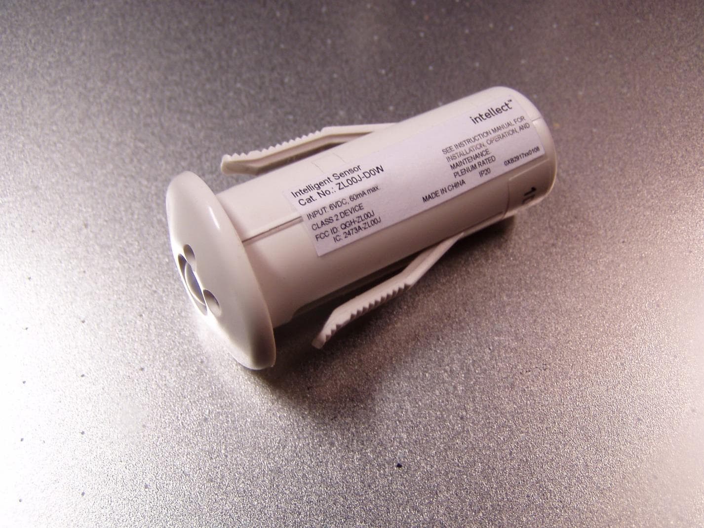
QGH-ZL00J
Apr 07, 2020ZL00J-D0W Intellect Sensor Head
Equipment Class
DTS - Digital Transmission System
QGH-ZBMG
Jan 02, 20200XB1803 Module
Equipment Class
DTS - Digital Transmission System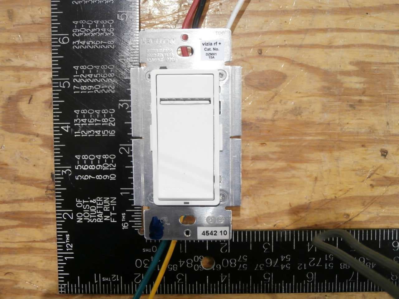
QGH-VRMX1
Dec 04, 2014Light Dimmer
Equipment Class
DXT - Part 15 Low Power Transceiver, Rx Verified