QGH-ZL00JZL00J-D0W Intellect Sensor Head
Leviton Manufacturing Co., Inc.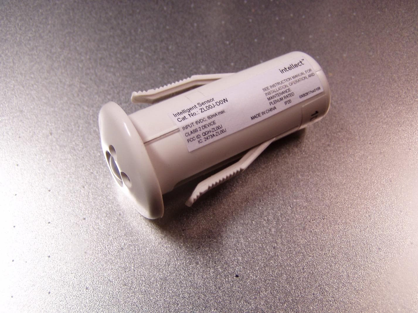
Click to zoom
Application Details
- Equipment Class
- DTS - Digital Transmission System
- Date of Grant
- Apr 07, 2020
- Application Purpose
- Original Equipment
- Date of Application
- Apr 07, 2020
- Equipment Note
- ZL00J-D0W Intellect Sensor Head
- Frequency Range
- 2405.00000000 - 2480.00000000
- Country
- United States
Documents & Files
Document Text
Text extracted from the exhibit documents filed with the FCC. Open a document above to read the original.
Users Manual
WARNINGS AND CAUTIONS • TO AVOID FIRE, SHOCK, OR DEATH; TURN OFF POWER at circuit breaker or fuse and test that power is off before wiring! • If you are unsure about any part of these instructions, consult an electrician. • To be installed and/or used in accordance with appropriate electrical codes and regulations. • Suitable for use in air handling spaces. Intellect TM Sensor Head Cat. No. ZL00J DI-000-ZL00J-22B-X2 Agency ENGLISH INSTALLATION INSTRUCTIONS DESCRIPTION • The Intellect TM enabled Sensor Head detects both light level and occupancy. The sensor uses passive infrared (PIR) for occupancy detection. To be effective, PIR technology requires direct line of sight to detect occupants (refer to product data sheets for field of view and appropriate application information). • The Sensor Head has a pre-attached trim ring which can be painted in the field to match mounting surface (Fig. 2). Pry away trim ring with a small screwdriver to paint and reattach when dry. • The Sensor Head may be installed into your fixture by the fixture manufacturer, or with certain fixtures types like downlights, adjacent to the fixture. When the sensor is pre-installed on a fixture, refer to fixture documentation for installation methods, means, and requirements. NOTES: • For connection only to Intellect TM enabled Power Control Module (PCM) or LED Module. • Maximum distance between Sensor Head and Power Control Module is 10 feet (3 m). • The cable between the Sensor Head and Power Control Module must be provided by the fixture manufacturer, and, is not field modifiable. Alternate lengths are available should the one provided be too short or long. Use only Intellect cable for connection between Sensor Head and Power Control Module. Connection cables are available in lengths of 12" 18", 24" and 30". See Cat No. ZLAEX Series Cables. • If pre-installed into a fixture, and you are replacing, refer to fixture instructions for appropriate installation. • Sensor head is designed to be mounted a maximum of 12 feet high, with fixture spacings at a spacing to mounting height of 1:1. INSTALLATION General Ceiling Mount (tile or sheetrock) 1. Cut 7/8" +/- 1/8" diameter hole in ceiling. 2. Run cable from Power Control Module through hole in ceiling and attach jack to Sensor Head. 3. Push Sensor head into ceiling until flush. NOTE: To remove from above ceiling depress tabs on side of Sensor Head and push back down through ceiling. • Under normal operation, the red LED blinks when Occupancy is detected. This LED can be disabled through software. • Sensor head can be restored to factory default by pushing up a thin object through the groove situated in between the 2 light pipes (as shown in Fig. 3) and holding the switch until the LED indicator blinks rapidly (approx. 10 seconds) and then removing. A factory default (out of the box) operation will: - Automatically turn lights ON upon detection of occupancy. - Turn lights OFF after vacancy is detected, and 30 minutes has elapsed. - Automatically calibrate daylight harvesting. - All fixtures will operate independently of each other until wirelessly connected to a Room Controller. • For changes to default operation, system must be configured. Refer to your system documentation for details. • Test Mode: Pressing and releasing the switch will cycle through 0%, 100%, 5%. • Manual Pairing: Manually pairing the sensor to a room controller can be achieved by first putting the room controller in pairing mode, then, pressing and releasing the switch. This will highlight this fixture in the commissioning app. OPERATION AND TROUBLESHOOTING Fig. 3 Fig. 1 Fig. 2 Reset Switch Levier Interruptor de reinicio Trim Ring Anneau décoratif Anillo de ajuste Reset Switch Levier Interruptor de reinicio Groove Rainure Ranura Switch Access Accès au levier Acceso del interruptor LIMITED 2 YEAR WARRANTY AND EXCLUSIONS Leviton warrants to the original consumer purchaser and not for the benefit of anyone else that this product at the time of its sale by Leviton is free of defects in materials and workmanship under normal and proper use for two years from the purchase date. Leviton’s only obligation is to correct such defects by repair or replacement, at its option. For details visit www.leviton.com or call 1-800-824-3005. This warranty excludes and there is disclaimed liability for labor for removal of this product or reinstallation. This warranty is void if this product is installed improperly or in an improper environment, overloaded, misused, opened, abused, or altered in any manner, or is not used under normal operating conditions or not in accordance with any labels or instructions. There are no other or implied warranties of any kind, including merchantability and fitness for a particular purpose, but if any implied warranty is required by the applicable jurisdiction, the duration of any such implied warranty, including merchantability and fitness for a particular purpose, is limited to two years. Leviton is not liable for incidental, indirect, special, or consequential damages, including without limitation, damage to, or loss of use of, any equipment, lost sales or profits or delay or failure to perform this warranty obligation. The remedies provided herein are the exclusive remedies under this warranty, whether based on contract, tort or otherwise. For Technical Assistance Call: 800-824-3005 - www.leviton.com FRANÇAIS DIRECTIVES Détecteur Intellect MC N o de cat. ZL00J AVERTISSEMENTS ET MISES EN GARDE • POUR ÉVITER LES RISQUES D’INCENDIE, DE DÉCHARGE ÉLECTRIQUE OU D’ÉLECTROCUTION, COUPER LE COURANT au fusible ou au disjoncteur et s’assurer que le circuit est bien coupé avant de procéder à l’installation. • À défaut de bien comprendre les présentes directives, en tout ou en partie, on doit faire appel à un électricien. • Installer et utiliser ce produit conformément aux codes de l’électricité en vigueur. • Ce produit convient aux espaces de traitement de l’air. DESCRIPTION • Le détecteur Intellect…
Text truncated - open the document above for the full version.
External Photos
ZL00J-D0W external edge view showing enclosure and product label. ZL00J-D0W external front view. ZL00J-D0W external rear view. ZL00J-D0W external side view 1. ZL00J-D0W external side view 2. ZL00J-D0W external side view 3. ZL00J-D0W external side view 4. ZL00J-D0W external side view with ruler for relative size.
ID Label/Location Info
ZL00J-D0W Product Label
Internal Photos
ZL00J‐D0W front side with radio. Radio is approximately 1/8” from top of plastic dome. ZL00J‐D0W back side
Operational Description
NOTES: SINGLE SOURCE: ALL ALTERNATES MUST HAVE ENGINEERING APPROVAL1. SEE FOLLOWING PAGES FOR PURCHASING INFO FROM DATA SHEET2. ITEM MUST BE ROHS COMPLIANT3. MANUFACTURING PART NUMBER EXPLANATION: SEE MANUFACTURER DATA SHEET FOR DETAILS NOTE: As of 09/23/2013 all new parts created to unified P/N system MANUFACTURER NAMEMANUFACTURER PART NUMBER JOHANSON2450AT18B100E LEVITON PART NUMBER (Global) 0XA9935890000 SHEET 1 OF 4 PROJECT NO. 02636 TITLE: ALL PRINTED COPIES ARE UNCONTROLLED DWG NO. REV SIZE A UNLESS OTHERWISE SPECIFIED: DO NOT SCALE DRAWING. ALL DIMENSIONS ARE IN INCHES. ALL ANGLES ARE IN DEGREES. The information in this document is the exclusive PROPRIETARY property of LEVITON MFG. CO., INC. It is disclosed with the understanding that acceptance or review by the recipient constitutes an undertaking by the recipient: (1) to hold this information in strict confidence. (2) not to disclose, duplicate, copy, or use the information, in whole or in part, for any purpose other than that for which disclosed. DWN BY CHK BY TOLERANCES THIRD ANGLE PROJECTION A 01/26/2015 01/26/2015 RY7 SCALE:1:1 ANTENNA CHIP 2.45GHz 01/26/2015 RY7 MFG ENGRG RY7 01/26/2015 1/2° .XX .XXX ± ± INCH .01 .005 ANGLES: ± .X .XX METRIC .2 mm .1 mm ± ± Copyright 2009. Unpublished. All Rights Reserved. RY7 0000000 DATEREV. 01/26/2015 NRD ECO NUMBER CHGD A APVD Production Release STATUS: - - -- - - - -- - - - -- - - - -- - NRD OXA9935-D01 SMT 2450 MHz AntennaP/N 2450AT18B100 Detail Specification: 08/10/09 Page 1 of 3 General Specifications Part Number 2450AT18B100 Input Power 3W max. Frequency Range 2400 - 2500 Mhz Impedance 50 Ω Peak Gain 0.5 dBi typ. (XZ-V) Operating Temperature -40 to +85°C Average Gain -0.5 dBi typ. (XZ-V) Reel Quanity 3,000 Return Loss 9.5 dB min. Terminal Configuration Packaging BulkSuffix = SEg. 2450AT18B100S No. Function P/N Style T & RSuffix = EEg. 2450AT18B100E 1 Feeding Point Suffix Termination 100% TinSuffix = None Eg. 2450AT18B100(E or S) 2 NC Style Tin / Lead Mechanical Dimensions Inmm L ±± W ±± T a ±± Mounting Considerations Mount these devices with brown mark facing up. Units: mm Line width should be designed to provide 50 Ω impedance matching characteristics. a) Without Matching Circuits b) With Matching Circuits Johanson Technology, Inc. reserves the right to make design changes without notice. All sales are subject to Johanson Technology, Inc. terms and conditions. www.johansontechnology.com 4001 Calle Tecate • Camarillo, CA 93012 • TEL 805.389.1166 FAX 805.389.1821 2009 Johanson Technology, Inc. All Rights Reserved Please consult Factory 0.0120.020 1.30 0.30 1.600.200.008 0.051 +.004/-.008+0.1/-0.2 "High Frequency Ceramic Solutions" 0.50 0.1260.0083.200.20 0.063 1 2 L W a T ) Matching Component JTI P/Ns: L-14C2N7JV4 L-14C2N2JV4 * 2.6 4.2 1.6 1.9 0.4 2.7nH 1.2pF 3.3nH JTI P/N for Matching Circuit: Cap (1.2pF): 500R07S1R2BV4T Inductor (2.7nH): L-07C2N7SV6T Inductor (3.3nH): L-07C3N3SV6T 2450 MHz AntennaP/N 2450AT18B100 Detail Specification: 08/10/09 Page 2 of 3 Typical Electrical Characteristics (T=25 o C) Test Board: Return Loss a) Without Matching Circuitb) With Matching Circuit Johanson Technology, Inc. reserves the right to make design changes without notice. All sales are subject to Johanson Technology, Inc. terms and conditions. www.johansontechnology.com 4001 Calle Tecate • Camarillo, CA 93012 • TEL 805.389.1166 FAX 805.389.1821 2009 Johanson Technology, Inc. All Rights Reserved "High Frequency Ceramic Solutions" ) ) ) ) ) ) ) ) ) Ground 13.5mm 6.5mm 39.5mm 6.5mm Matching Circuit No Ground 50Ω Feed Line Antenna 19mm 4mm 2450 MHz AntennaP/N 2450AT18B100 Detail Specification: 08/10/09 Page 3 of 3 Typical Radiation Patterns Johanson Technology, Inc. reserves the right to make design changes without notice. All sales are subject to Johanson Technology, Inc. terms and conditions. www.johansontechnology.com 4001 Calle Tecate • Camarillo, CA 93012 • TEL 805.389.1166 FAX 805.389.1821 2009 Johanson Technology, Inc. All Rights Reserved "High Frequency Ceramic Solutions" ) ) ) ) ) ) ) ) )
RF Exposure Info
This report must not be used to claim product certification, approval, or endorsement by NVLAP, NIST, or any agency of the U.S. Government. This Report shall not be reproduced, except in full without written approval of the laboratory. EAR-Controlled Data - This document contains technical data whose export and reexport/retransfer is subject to control by the U.S. Department of Commerce under the Export Administration Act and the Export Administration Regulations. The Department of Commerce’s prior written approval may be required for the export or re- export/retransfer of such technical data to any foreign person, foreign entity or foreign organization whether in the United States or abroad. More: https://www.bis.doc.gov/index.php/forms-documents/regulations-docs/14-commerce-country-chart/fileT Leviton Mfg Co, Inc ZL00J-D0W Intellect Sensor Head FCC 2.1091:2020 802.15.4 DTS Radio Report # LEVT0124.3 NVLAP Lab Code: 200630 CERTIFICATE OF EVALUATION 2018-09-14 Product compliance is the responsibility of the client; therefore, the tests and equipment modes of operation represented in this report were agreed upon by the client, prior to testing. The results of this test pertain only to the sample(s) tested. The specific description is noted in each of the individual sections of the test report supporting this certificate of test. This report reflects only those tests from the referenced standards shown in the certificate of test. It does not include inspection or verification of labels, identification, marking or user information. As indicated in the Statement of Work sent with the quotation, Element’s standard process is to always use the latest published version of the test methods even when earlier versions are cited in the test specification. Issuance of a purchase order was de facto acceptance of this approach. Otherwise, the client would have advised Element in writing of the specific version of the test methods they wanted applied to the subject testing Last Date of Evaluation: Tuesday, January 14, 2020 Leviton Mfg Co, Inc EUT: ZL00J-D 0W Intellect Sensor Head RF Exposure Evaluation Standards Specification Method FCC 2.1091:2020 FCC 447498 D01 General RF Exposure Guidance v06 Results Method Clause Description Applied Results Comments 7.1 Maximum Permissible Exposure Yes Pass None Deviations From Evaluation Standards None Approved By: Donald Facteau, Process Architect Report No. LEVT0124.3EAR-Controlled Data2/9 REVISION HISTORY 2018.07.17 Revision Number Description Date (yyyy-mm-dd) Page Number 00 None Report No. LEVT0124.3EAR-Controlled Data3/9 ACCREDITATIONS AND AUTHORIZATIONS 2019.03.08 United States FCC - Designated by the FCC as a Telecommunications Certification Body (TCB). Certification chambers, Open Area Test Sites, and conducted measurement facilities are listed with the FCC. A2LA - Accredited by A2LA to ISO / IEC 17065 as a product certifier. This allows Element to certify transmitters to FCC and IC specifications. NVLAP - Each laboratory is accredited by NVLAP to ISO 17025 Canada ISED - Recognized by Innovation, Science and Economic Development Canada as a Certification Body (CB) and as a CAB for the acceptance of test data. European Union European Commission – Within Element, we have a EU Notified Body validated for the EMCD and RED Directives. Australia/New Zealand ACMA - Recognized by ACMA as a CAB for the acceptance of test data. Korea MSIT / RRA - Recognized by KCC’s RRA as a CAB for the acceptance of test data. Japan VCCI - Associate Member of the VCCI. Conducted and radiated measurement facilities are registered. Taiwan BSMI – Recognized by BSMI as a CAB for the acceptance of test data. NCC - Recognized by NCC as a CAB for the acceptance of test data. Singapore IDA – Recognized by IDA as a CAB for the acceptance of test data. Israel MOC – Recognized by MOC as a CAB for the acceptance of test data. Hong Kong OFCA – Recognized by OFCA as a CAB for the acceptance of test data. Vietnam MIC – Recognized by MIC as a CAB for the acceptance of test data. SCOPE For details on the Scopes of our Accreditations, please visit: https://www.nwemc.com/emc-testing-accreditations Report No. LEVT0124.3EAR-Controlled Data4/9 FACILITIES 2019.03.08 California Labs OC01-17 41 Tesla Irvine, CA 92618 (949) 861-8918 Minnesota Labs MN01-10 9349 W Broadway Ave. Brooklyn Park, MN 55445 (612)-638-5136 Oregon Labs EV01-12 6775 NE Evergreen Pkwy #400 Hillsboro, OR 97124 (503) 844-4066 Texas Labs TX01-09 3801 E Plano Pkwy Plano, TX 75074 (469) 304-5255 Washington Labs NC01-05 19201 120 th Ave NE Bothell, WA 98011 (425)984-6600 NVLAP NVLAP Lab Code: 200676-0 NVLAP Lab Code: 200881-0 NVLAP Lab Code: 200630-0 NVLAP Lab Code:201049-0 NVLAP Lab Code: 200629-0 Innovation, Science and Economic Development Canada 2834B-1, 2834B-3 2834E-1, 2834E-3 2834D-1 2834G-1 2834F-1 BSMI SL2-IN-E-1154R SL2-IN-E-1152R SL2-IN-E-1017 SL2-IN-E-1158R SL2-IN-E-1153R VCCI A-0029 A-0109 A-0108 A-0201 A-0110 Recognized Phase I CAB for ISED, ACMA, BSMI, IDA, KCC/RRA, MIC, MOC, NCC, OFCA US0158 US0175 US0017 US0191 US0157 Report No. LEVT0124.3EAR-Controlled Data5/9 PRODUCT DESCRIPTION 2018-07-17 Client and Equipment Under Evaluation Information Company Name: Leviton Mfg Co, Inc Address: 20497 SW Teton Avenue City, State, Zip: Tualatin, OR 97062 Evaluation Requested By: Mark Darula EUT: ZL00J-D0W Intellect Sensor Head Date of Evaluation: Tuesday, January 14, 2020 Information Provided by the Party Requesting the Evaluation Functional Description of the Equipment: The ZL00J-D0W is a ceiling mounted, 1/2" to 2" thick, passive infrared sensor head used for occupancy detection and operates over Zigbee frequencies to communicate with other Leviton Zigbee products. Objective: To demonstrate compliance with FCC requirements for RF exposure for 2.1091 mobile/fixed devices. Report No. LEVT0124.3EAR-Controlled Data6/9 RF Exposure Condition 2018-07-17 The following RF Exposure conditions were used for the assessment documented in this report…
Text truncated - open the document above for the full version.
Test Report
This report must not be used to claim product certification, approval, or endorsement by NVLAP, NIST, or any agency of the federal government of the United States of America. This Report shall not be reproduced, except in full without written approval of the laboratory. Leviton Mfg Co, Inc Neuron Sensor Head FCC 15.207:2016 FCC 15.247:2016 2.4 GHz DTS Radio Report # LEVT0124 Rev. 1 NVLAP Lab Code: 200630-0 CERTIFICATE OF TEST 2018-09-14 Product compliance is the responsibility of the client; therefore, the tests and equipment modes of operation represented in this report were agreed upon by the client, prior to testing. The results of this test pertain only to the sample(s) tested. The specific description is noted in each of the individual sections of the test report supporting this certificate of test. This report reflects only those tests from the referenced standards shown in the certificate of test. It does not include inspection or verification of labels, identification, marking or user information. Last Date of Test: December 6, 2016 Leviton Mfg Co, Inc Model: Neuron Sensor Head Radio Equipment Testing Standards Specification Method FCC 15.207:2016 ANSI C63.10:2013 FCC 15.247:2016 Results Method Clause Test Description Applied Results Comments 6.2 Powerline Conducted Emissions Yes Pass 6.5, 6.6, 11.12.1, 11.13.2 Spurious Radiated Emissions Yes Pass 11.6 Duty Cycle Yes N/A Characterization of radio operation. 11.8.2 Occupied Bandwidth Yes Pass 11.9.2.2.4 Output Power Yes Pass 11.10.2 Power Spectral Density Yes Pass 11.11 Spurious Conducted Emissions Yes Pass 11.11 Band Edge Compliance Yes Pass Deviations From Test Standards None On July 1, 2016, Northwest EMC was purchased by Element Materials Technology. All laboratory accreditations, designations, and recognitions were transferred from Northwest EMC to Element Materials Technology. No changes were made to the facilities, equipment, procedures, or personnel. This test report contains test data produced by Northwest EMC prior to the purchase on July 1, 2016, and by Element Materials Technology after that date. All the test data in this test report is accredited and maintains the same recognition as described herein. This test report was re-issued so that the ILAC mark could appear on the cover of the test report. The customer has declared that the results continue to be representative of the current device. The equipment design and manufacturing process has not changed since the original testing/evaluation was performed and documented. Approved By: Kyle Holgate, Operations Manager Report No. LEVT0124 Rev 1EAR-Controlled Data2/52 REVISION HISTORY REV 2014.10.14 Revision Number Description Date Page Number 01 Updated report cover and certificate of test to Element Materials Technology. 2020-01-13 1, 2 Added statement to certificate of test. 2020-01-13 2 Added Ilac logo to cover page. 2020-01-13 1 Report No. LEVT0124 Rev 1EAR-Controlled Data3/52 ACCREDITATIONS AND AUTHORIZATIONS REV 2016.7.25 United States FCC - Designated by the FCC as a Telecommunications Certification Body (TCB). Certification chambers, Open Area Test Sites, and conducted measurement facilities are listed with the FCC. A2LA - Accredited by A2LA to ISO / IEC 17065 as a product certifier. This allows Northwest EMC to certify transmitters to FCC and IC specifications. NVLAP - Each laboratory is accredited by NVLAP to ISO 17025 Canada ISED - Recognized by Innovation, Science and Economic Development Canada as a Certification Body (CB). Certification chambers and Open Area Test Sites are filed with ISED. European Union European Commission – Validated by the European Commission as a Notified Body under the R&TTE Directive. Australia/New Zealand ACMA - Recognized by ACMA as a CAB for the acceptance of test data. Korea MSIP / RRA - Recognized by KCC’s RRA as a CAB for the acceptance of test data. Japan VCCI - Associate Member of the VCCI. Conducted and radiated measurement facilities are registered. Taiwan BSMI – Recognized by BSMI as a CAB for the acceptance of test data. NCC - Recognized by NCC as a CAB for the acceptance of test data. Singapore IDA – Recognized by IDA as a CAB for the acceptance of test data. Israel MOC – Recognized by MOC as a CAB for the acceptance of test data. Hong Kong OFCA – Recognized by OFCA as a CAB for the acceptance of test data. Vietnam MIC – Recognized by MIC as a CAB for the acceptance of test data. SCOPE For details on the Scopes of our Accreditations, please visit: http://www.nwemc.com/accreditations/ http://gsi.nist.gov/global/docs/cabs/designations.html Report No. LEVT0124 Rev 1EAR-Controlled Data4/52 FACILITIES REV 2016.7.25 California Labs OC01-13 41 Tesla Irvine, CA 92618 (949) 861-8918 Minnesota Labs MN01-08, MN10 9349 W Broadway Ave. Brooklyn Park, MN 55445 (612)-638-5136 New York Labs NY01-04 4939 Jordan Rd. Elbridge, NY 13060 (315) 554-8214 Oregon Labs EV01-12 22975 NW Evergreen Pkwy Hillsboro, OR 97124 (503) 844-4066 Texas Labs TX01-09 3801 E Plano Pkwy Plano, TX 75074 (469) 304-5255 Washington Labs NC01-05 19201 120 th Ave NE Bothell, WA 98011 (425)984-6600 NVLAP NVLAP Lab Code: 200676-0 NVLAP Lab Code: 200881-0 NVLAP Lab Code: 200761-0 NVLAP Lab Code: 200630-0 NVLAP Lab Code:201049-0 NVLAP Lab Code: 200629-0 Innovation, Science and Economic Development Canada 2834B-1, 2834B-3 2834E-1 N/A 2834D-1, 2834D-2 2834G-1 2834F-1 BSMI SL2-IN-E-1154R SL2-IN-E-1152R N/A SL2-IN-E-1017 SL2-IN-E-1158R SL2-IN-E-1153R VCCI A-0029 A-0109 N/A A-0108 A-0201 A-0110 Recognized Phase I CAB for ACMA, BSMI, IDA, KCC/RRA, MIC, MOC, NCC, OFCA US0158 US0175 N/A US0017 US0191 US0157 Report No. LEVT0124 Rev 1EAR-Controlled Data5/52 Test Setup Block Diagrams REV 2016.10.04 Antenna Port Conducted Measurements Near Field Test Fixture Measurements Spurious Radiated Emissions EUT DC Block and Attenuator Spectrum Analyzer RF Adapter Coaxial Cable 3m Test Distance Spectrum Analyzer Measurement Antenna Coaxial Cable EUT Flush Mounted Turn table, Non-reflective fo…
Text truncated - open the document above for the full version.
Test Setup Photos
POWERLINE CONDUCTED EMISSIONS WTD.2016.09.09 , POWERLINE CONDUCTED EMISSIONS WTD.2016.09.09 , SPURIOUS RADIATED EMISSIONS photo PSA-ESCI 2016.07.22 photos FCC SRE 001.jpg FCC SRE 002.jpg SRE 002 SPURIOUS RADIATED EMISSIONS photo PSA-ESCI 2016.07.22 photos FCC SRE 003.jpg FCC SRE 004.jpg SRE 004 SPURIOUS RADIATED EMISSIONS photo PSA-ESCI 2016.07.22 photos FCC SRE 007.jpg SPURIOUS RADIATED EMISSIONS photo PSA-ESCI 2016.07.22 photos FCC SRE 010.jpg XMit 2016.09.29 aDIRECT CONNECT 003 (1).jpg aDIRECT CONNECT 003 (2).jpg DIRECT CONNECT
Contact Information
Applicant
Frank Tse(Manager)
Test Firm
Element Materials TechnologyRenee Walker
Technical Specifications
| # | Rule Parts | Frequency Range | Power Output |
|---|---|---|---|
| 1 | 15C | 2.40 GHz - 2.48 GHz | 2.70 mW |
Other Applications from Leviton Manufacturing Co., Inc.

QGH-B167601
Jun 25, 2020Lumina Wall Dimmer and Wireless Load Control Dimmer
Equipment Class
DTS - Digital Transmission System
QGH-B167602
Jun 25, 2020Lumina RF Wall Switch and Wireless Load Controller
Equipment Class
DTS - Digital Transmission System
QGH-PVDIM
Apr 07, 2020O5C04-IDW, O5C20-MDW, 06C04-IDW, 06C20-MDW, V6C04-IDW, V6C20-MDW
Equipment Class
DTS - Digital Transmission System
QGH-ZBMG
Jan 02, 20200XB1803 Module
Equipment Class
DTS - Digital Transmission System
QGH-VRMX1
Dec 04, 2014Light Dimmer
Equipment Class
DXT - Part 15 Low Power Transceiver, Rx Verified