QGH-LEV300CLevNet RF 300C
Leviton Manufacturing Co., Inc.
Click to zoom
Application Details
- Equipment Class
- DSR - Part 15 Remote Control/Security Device Transceiver
- Date of Grant
- Jun 04, 2012
- Application Purpose
- Original Equipment
- Date of Application
- Jun 04, 2012
- Equipment Note
- LevNet RF 300C
- Frequency Range
- 315.00000000 - 315.00000000
- Country
- United States
Documents & Files
Document Text
Text extracted from the exhibit documents filed with the FCC. Open a document above to read the original.
Users Manual
LevNet RF USB computer link Cat. No. WSCOM-03W INSTALLATION AND QUICK START GUIDE English WARNINGS AND CAUTIONS: • Do not use this device with a larger antenna than provided or specified. • Always ensure antenna is securely fastened for optimum performance. • Performance of device can also be affected if used outside its temperature range. DESCRIPTION: The LevNet RF computer link (WSCOM) is a USB transceiver (transmitter and receiver) tool which is utilized for testing, monitoring, and commissioning in a LevNet RF or any EnOcean enabled environment. It can be attached to any PC computer systems (desktop, laptop, or notebook) and other USB host devices (tablets). This tool works by receiving and transmitting at 315MHz using the EnOcean wireless protocol packets and allows connectivity to the world of EnOcean based wireless products. The WSCOM tool works with EnOcean DolphinView Basic software for Windows ® XP/7 to provide a visual environment for analyzing wireless radio messages (telegrams). With the provided antenna the device has the following operational receiving and transmitting distances: - Line of site: Up to 200ft receiving and 200ft transmitting in hallways. - Line of site outdoors: Up to 250ft receiving and 200ft transmitting range. - Indoor drywall: Up to 100ft range, through max. 5 walls. - Fire safety and Ferroconcrete walls / ceilings: Coverage is not guaranteed. FEATURES: • Receive telegrams from EnOcean enabled devices including self-powered switches and sensors. • Signal strength analysis (RSSI) of transmitted wireless telegrams. • Send messages to control EnOcean enabled devices. • Remote configuration of devices that support the Remote Management capability. • Compatible with EnOcean’s DolphinView and other 3rd party software. • Supports all message formats of EnOcean Equipment Profile (EEP) 2.1. • Compatible with EnOcean Serial Protocol 3 (ESP3). • Offers programmable repeater (1/2 Level). COMPATIBLE DEVICES: Any EnOcean Alliance enabled device which conforms to the EnOcean Equipment Profile (EEP) is compatible with the WSCOM tool. This includes but is not limited to 3 & 5 wire relays, room controllers, thermostats, occupancy sensors, wall box receiver switches, unpowered switches, and light sensors made by Leviton as well as other EnOcean Alliance companies which support EEP 2.0 and above. EQUIPMENT NEEDED FOR INSTALLATION: • Desktop/laptop/notebook PC or similar USB Enabled Device. • DolphinView Basic (minimum) or other Third Party Software. DolphinView Basic System requirements: Windows ® XP, Windows ® Vista or Windows ® 7; .NET Framework 3.5 installed; CPU 1.5GHz, 1 GB RAM, 200 MB Disc Space; Screen resolution 1280x768 with DirectX 9 support. • FTDI Drivers (Included with DolphinView). • USB Extension Cable (Optional). INSTALLATION: This installation guide concentrates on the usage of the WSCOM tool with the EnOcean DolphinView Basic software package. DolphinView Basics allows for signal monitoring of transmitted wireless telegrams. In order to transmit telegrams or utilize Remote Management features the DolphinvView Advanced or other third party software package will be required. See details at the bottom of this documentation for these other software options. 1. Make sure the WSCOM tool is not plugged into the PC. 2. Download DolphinView Basic from Leviton: www.leviton.com/LevNetRF/DolphinViewBasic 3. Install DolphinView Basic 3.2.1.0 or newer on your Windows ® PC. Be sure to accept all selections: Uninstall previous DolphinView, Create desktop icon, and Update or install FTDI drivers version 2.08.02 (or newer). 4. Restart your PC after installation is complete. 5. Start DolphinView. 6. Plug in the LevNet RF USB computer link. When first plugging in the WSCOM tool the red power LED will turn ON while the amber and green LED will blink twice at the same time. This signals the device has received power, booted up, and is working properly. 7. The WSCOM Tool should automatically be detected by the Windows ® XP/7 PC and any new drivers required will be installed. • It is important to allow Windows ® to search for software. This is a process that can take up to 2 minutes. Both a USB Com Port Driver and USB Serial Port Driver will be installed. • Note: If the driver fails to install, a manual install of the FTDI driver maybe required. Refer to the troubleshooting section towards the end of this document for more details. 8. In the drop-down area next to Connect [F5] select the COM PORT that shows the “GATEWAYCTRL” device with the green check mark (figure 1). 9. Click Connect [F5] and the DolphinView software will now be able to access the WSCOM USB tool. • Any 315MHz EnOcean telegram transmitted will appear in the Telegram Log at the bottom of screen. 10. Use an unpowered switch (WSS0S) or similar transmitter to verify EnOcean telegrams are being received and the WSCOM tool is working properly. DEVICE STATUS LED’S: • Red power LED: Device is being power from host. • Amber receive LED: Device received a wireless telegram. • Green transmit LED: Device transmitted a wireless telegram (Transmit is not available with DolphinView Basic). PRODUCT USAGE: With software and the device plugged into a PC the LevNet RF computer link (WSCOM) can be used in the following ways: • As a communication gateway between EnOcean enabled devices. • For monitoring and logging a site having EnOcean enabled devices. • For testing new or pre-existing installs. • As a repeater. COMMUNICATION GATEWAY USAGE: Utilizing a third party software package and the WSCOM tool opens the door to wireless control of all devices within range of the centrally controlled Gateway PC. In this environment the WSCOM tool and accompanying software can simulate all transmitting devices within range and then can be learned into all receiving devices. This situation allows for the Gateway PC, if desired, to monitor and handle all of the lighting controls. MONITORING AND LOGGING: The WSCOM tool can be connected to a PC in …
Text truncated - open the document above for the full version.
Cover Letter(s)
Northwest EMC TCB Compliance Opinion Rev. 7/1/10 LEVT0048 Information about the Applicant Grantee (Company Name) Leviton Manufacturing Co., Inc. FCC Contact Person Frank Tse Address 59-25 Little Neck PKWY City, State, Zip Little Neck, New York 11362 Job Number LEVT0048 Model LevNet RF 300C FCC ID QGH-LEV300C Agent Kenneth Vannice Approval Type Original Single Modular Equipment Class DXT Part 15, Low Power Transceiver, Rx Verified Rule Part 15.231 Overview Leviton Manufacturing is seeking full modular approval of their low power transmitter, model LevNet RF 300C, under FCC rule part 15.231. The transmitter module, manufactured by ENOCEAN, operates at 315 MHz. The transmitter was tested as a standalone device. User manual and other documentation show the transmitter housed in Leviton's Model WSCOM-03W USB configuration, which connects directly to a computer and serves as a link in Leviton's RF network. Confidentiality requested for allowed files. Request is properly addressed and referenced. A letter listing the applicable modular requirements was submitted. Recommendation All items have been resolved and completed to my satisfaction; therefore I recommend this application for approval. Signature Dave Tolman, TCB Committee 5/31/2012
External Photos
Page 1 of 2 Internal Photos: WSCOM-03W 23 Apr 2012 WSCOM-03W Top PCB (Showing Module) Figure 1. WSCOM-03W Top (Component Side) Figure 2. WSCOM-03W Top (Radio Section) Radio RP-SMA 50 Ohm Antenna Connector Antenna Tuning Circuit Page 2 of 2 WSCOM-03W Bottom PCB Figure 3. WSCOM-03W Bottom
ID Label/Location Info
Page 1 of 3 Label: WSCOM-03W 15 May 2012 Label (Industry Canada ID and FCC) Figure 1. WSCOM-03W Label (Same for IC and FCC) Label Dimension Figure 2. WSCOM-03W Label Dimensions Page 2 of 3 Label Specifications LABEL MATERIAL: 0.002" THICK CLEAR POLYESTER WITH 0.001" THICK CLEAR POLYESTER OVERLAY,L-46 PERMANENT PRESSURE SENSITIVE ADHESIVE BACK. LABELS SHALL BE TRACEABLE UL RECOGNIZED MARKING AND LABELING SYSTEMS (PGDQ2) SUITABLE FOR USE ON 80 DEGREE C POLYCARBONATE PLASTIC OR METAL SURFACES. ARTWORK PRINTED WITH WHITE TEXT ON BLACK BACKGROUND Label Location The black label with white text will be printed and placed on the back of the WSCOM-03W unit on the non-textured surface. Figure 3. WSCOM-03W Label (White text on black background) Figure 4. Back of WSCOM-03W: Label affixes to non-textured surface Page 3 of 3 Module Label (Industry Canada ID and FCC) Figure 5. Label on TCM300C Chip showing Modular Approval Module Label Dimension Figure 6. Modular Label Dimensions Module Label Specifications This is a print on demand label. Fill in the software version field (x.xx) with latest software version. Replace "MM/DD/YY" with numerics of the Month, Day, and Year the device is programed. Material: Polyester (Mylar), Leviton P/N: PK-92503-10-00-CL. Print BLACK ink on white background, Text Style: Arial (Regular) Module Label Location The white label with black text is placed on U4 IC, over another label that exist on the IC. Figure 7. Module Label affixes to U4, TCM300C IC Figure 8. U4 (TCM300C) with modular label attached
Internal Photos
Top View Bottom View
Operational Description
AR026 GSM 315MHz Antenna W ellshow ® For more information, contact [email protected] TEL: +886 2-2427-0488 FAX: +886 2-2426-0387 9F., No.181, Nanrong Rd., Ren-ai Dist., Keelung City 200, Taiwan (R.O.C.) www.Wellshow.com Rev. 1.00 1 / 2 www.wellshow.com www.rfcoaxcable.com For more information, contact [email protected] TEL: +886 2-2423-9376 FAX: +886 2-2426-0387 9F., No.181, Nanrong Rd., Ren-ai Dist., Keelung City 200, Taiwan (R.O.C.) GSM 315MHz Antenna Product No. AR026WSG2519N (RP-SMA Plug) AR026WSG2501N (SMA Plug) Structure Figure MechanicalElectrical Antenna CoverTPEE (Black) Antenna BasePC Operating Temperature -20°C~+70°C ConnectorRP SMA Male (19N) SMA Male (01N) Cable Type UL 3385 AWG 24 Stranded Ground plane size4.00" x 4.00" Frequency Range315MHz Impedance50 Ω VSWR2.0 Max typ. at center Return Loss-12.651dB@315MHz Electrical Wave1/2λ Dipole RadiationOmni PolarizationVertical Frequency Printing Unit: mm AR026 GSM 315MHz Antenna W ellshow ® For more information, contact [email protected] TEL: +886 2-2427-0488 FAX: +886 2-2426-0387 9F., No.181, Nanrong Rd., Ren-ai Dist., Keelung City 200, Taiwan (R.O.C.) www.Wellshow.com Rev. 1.00 2 / 2 www.wellshow.com www.rfcoaxcable.com For more information, contact [email protected] TEL: +886 2-2423-9376 FAX: +886 2-2426-0387 9F., No.181, Nanrong Rd., Ren-ai Dist., Keelung City 200, Taiwan (R.O.C.) Test results Return Loss VSWR
Operational Description
Typical VSWR ™ ANT-315-CW-HWR-xxx DATA SHEET Product DimensionsDescription Features Electrical Specifications Ordering Information HWR Series antennas deliver outstanding performance in a rugged and cosmetically attractive package. The articulating base allows the antenna to tilt 90 degrees and rotate 360 degrees. The antennas attach via a standard SMA or Part 15 compliant RP-SMA connector. Custom colors and connectors are available for volume OEM customers. 5.59” (142.0) 1.02” (26.0) 0.32” (8.2) Electrical specifications and plots measured on 4.00” x 4.00” reference ground plane 0.39” (10.0) 4.57” (116.0) Polar Plot & Gain Information Antenna Factor159 Ort Lane Merlin, OR 97532 www.antennafactor.com 541-956-0931 (phone) 541-471-6251 (fax) Rev 07-26-10 •Low cost •Tilts and rotates •Omni-directional pattern •Outstanding VSWR •Rugged & damage-resistant •Standard SMA or Part 15 compliant RP-SMA connector •Custom colors and terminations for volume OEMs •Use with plastic* or metal enclosures •Internal O-ring seal on connector •Center Freq.315MHz •Recmd. Freq. Range 305-325MHz •Wavelength1/4-wave •VSWR<2.0 typ. at center •Impedance50 ohms •ConnectorRP-SMA or SMA •ANT-315-CW-HWR-RPS (with RP-SMA connector) •ANT-315-CW-HWR-SMA (with SMA connector) * Requires proximity ground plane CENTER 315.000MHz SPAN 200.000MHz S11 SWR 1.769 ANT-315-CW-RCS DATA SHEET Product DimensionsDescription Electrical Specifications Ordering Information 2.11” (53.5) 0.33” (8.5) 0.28” (7.0) 1.77” (45.0) 0.31” (8.0) 0.37” (9.4) Electrical specifications and plots measured on 4.00” x 4.00” reference ground plane * Requires proximity ground plane Features The RCS Series is ideally suited for products requiring an attractive, yet compact, 1/4-wave antenna in a right-angle form factor. The antennas attach via a Part 15 compliant RP-SMA connector. Rev 07-22-08 Typical VSWR Antenna Factor159 Ort Lane Merlin, OR 97532 www.antennafactor.com 541-956-0931 (phone) 541-471-6251 (fax) VSWR Graph •Reduced height helical whip •Right-angle mount •Excellent performance •Omni-directional pattern •Fully weatherized •SMA or Part 15 compliant RP-SMA connector •Use with plastic* or metal enclosures •Center Freq.315MHz •Bandwidth10MHz •Wavelength1/4-wave •VSWR<2.0 typ. at center •Impedance50 ohms •ConnectorRP-SMA •ANT-315-CW-RCS CENTER 315.000MHz SPAN 200.000MHz S11 SWR 1.317 ANT-315-CW-RAH DATA SHEET Product DimensionsDescription Features Electrical Specifications Ordering Information The RAH Series utilizes a helical element to greatly reduce the physical length of the antenna housing. They are ideal for products requiring an ultra- compact, aesthetically pleasing antenna in a right angle form factor. Despite their tiny size, they are ruggedly constructed and able to withstand punishing environments just like our larger whips. The antennas attach via a Part 15 compliant RP-SMA connector. 1.85” (47.0) 0.24” (6.0) 0.32” (8.0) 1.61” (41.0) H0.32” (8.0) Electrical specifications and plots measured on 4.00”x 4.00” reference ground plane CENTER 315.000MHz SPAN 200.000MHz S11 SWR 1.283 * Requires proximity ground plane Rev 10-10-11 Typical VSWR Antenna Factor159 Ort Lane Merlin, OR 97532 www.antennafactor.com 541-956-0931 (phone) 541-471-6251 (fax) VSWR Graph •Low cost •Ultra-compact •Right angle mount •Excellent performance •Omnidirectional pattern •Fully weatherized •Flexible main shaft •Rugged & damage-resistant •Part 15 compliant RP-SMA connector •Use with plastic* or metal enclosures •Center Freq. 315MHz •Bandwidth 7MHz •Wavelength 1/4-wave •VSWR<1.9 typ. at center •Impedance 50 ohms •Connector RP-SMA •ANT-315-CW-RAH Page 1 of 4 Antenna Info: WSCOM-03W 14 Mar 2012 List of Antennas All antennas listed utilize an RP-SMA connector. These are all ¼ Wave Monopole antennas. Maximum gain (External 50 Ohm passive antenna): <= 0 dBi Shipping Antenna (1/4 Wave antenna): This antenna is shipped with product and has the greatest gain: 1) Wellshow AR026WSG2519N: 315MHz, 50 Ohms, articulating base, VSWR <=2.0, 151.2mm a. Max Gain: <= 0dBi Alternative Antennas (1/4 Wave antenna): These antennas are not shipped with the product but can be used in case the original is lost or needs replaced. All of them have slightly less gain than the Wellshow being shipped with the product. 1) Antenna Factor ANT-315-CW-HWR-RPS: 315MHz, 50 Ohms, articulating base, VSWR < 2.0, 142mm a. Max Gain: <= -1dBi 2) Antenna Factor ANT-315-CW-RAH: 315MHz, 50 Ohms, right-angle, VSWR < 1.9, 47mm (53.5mm actual) a. Max Gain: <= -11dBi 3) Antenna Factor ANT-315-CW-RCS: 315MHz, 50 Ohms, right-angle, VSRW < 2.0, 53.5mm a. Max Gain: <= -12dBi Pictures Figure 1. ANT-315-CW-RAH (Antenna Factor) ANT-315-CW-RCS (Antenna Factor) Page 2 of 4 Figure 2. ANT-315-CW-HWR-RPS (Antenna Factor) Page 3 of 4 Figure 3. AR026WSG2519N (Wellshow) Page 4 of 4 Figure 4. All Antennas
Test Report
Leviton Manufacturing Company WSCOM-03W Report #: LEVT0047 Rev. 1 Report Prepared By Northwest EMC Inc. NORTHWEST EMC – (888) 364-2378 – www.nwemc.com California – Minnesota – Oregon – New York – Washington 22975 NW Evergreen Parkway Suite 400 Hillsboro, Oregon 97124 Certificate of Test Last Date of Test: May 14, 2012 Leviton Manufacturing Company Model: WSCOM-03W Emissions Test Description Specification Test Method Pass/Fail Occupied Bandwidth FCC 15.231:2012 ANSI C63.10:2009 Pass Field Strength of Fundamental FCC 15.231:2012 ANSI C63.10:2009 Pass Duty Cycle FCC 15.231:2012 ANSI C63.10:2009 Pass Spurious Radiated Emissions FCC 15.231:2012 ANSI C63.10:2009 Pass AC Powerline Conducted Emissions FCC 15.207:2012 ANSI C63.10:2009 Pass Deviations From Test Standards None Approved By: Don Facteau, IS Manager NVLAP Lab Code: 200630-0 Test Facility The measurement facility used to collect the data is located at: Northwest EMC, Inc. 22975 NW Evergreen Parkway, Suite 400 Hillsboro, OR 97124 Phone: (503) 844-4066 Fax: 844-3826 This site has been fully described in a report filed with and accepted by the FCC (Federal Communications Commission) and Industry Canada (Site filing #2834D-1). This report must not be used to claim product certification, approval, or endorsement by NVLAP, NIST, or any agency of the federal government of the United States of America. Product compliance is the responsibility of the client, therefore the tests and equipment modes of operation represented in this report were agreed upon by the client, prior to testing. This Report may only be duplicated in its entirety. The results of this test pertain only to the sample(s) tested. The specific description is noted in each of the individual sections of the test report supporting this certificate of test. Revision History Revision 09/01/11 Revision Number Description Date Page Number 00 None 01 Commissioning Tool (under EUT Description) changed to LevNet RF USB computer link 5-15-2012 8 01 Updated the last date of testing throughout report 5-15-2012 2, 7, 9 01 Replaced Spurious Radiated Emissions data 5-15-2012 19-21 Accreditations and Authorizations Revision 09/01/11 FCC Accredited by NVLAP for performance of FCC radio, digital, and ISM device testing. Our Open Area Test Sites, certification chambers, and conducted measurement facilities have been fully described in reports filed with the FCC and accepted by the FCC in letters maintained in our files. Northwest EMC has been accredited by ANSI to ISO / IEC Guide 65 as a product certifier. We have been designated by the FCC as a Telecommunications Certification Body (TCB). This allows Northwest EMC to certify transmitters to FCC specifications in accordance with 47 CFR 2.960 and 2.962. NVLAP Northwest EMC, Inc. is accredited under the National Voluntary Laboratory Accreditation Program (NVLAP) for satisfactory compliance with the requirements of ISO/IEC 17025 for Testing Laboratories. NVLAP is administered by the National Institute of Standards and Technology (NIST), an agency of the U.S. Commerce Department. The NVLAP accreditation encompasses Electromagnetic Compatibility Testing in accordance with the European Union EMC Directive 2004/108/EC, and ANSI C63.4. Additionally, Northwest EMC is accredited by NVLAP to perform radio testing in accordance with the European Union R&TTE Directive 1999/5/EEC, the requirements of FCC, and the RSS radio standards for Industry Canada. Industry Canada Accredited by NVLAP for performance of Industry Canada RSS and ICES testing. Our Open Area Test Sites and certification chambers comply with RSS-Gen, Issue 2 and have been filed with Industry Canada and accepted. Northwest EMC has been accredited by ANSI to ISO / IEC Guide 65 as a product certifier. We have been designated by NIST and recognized by Industry Canada as a Certification Body (CB) per the APEC Mutual Recognition Arrangement (MRA). This allows Northwest EMC to certify transmitters to Industry Canada technical requirements. (Site Filing Numbers - Hillsboro: 2834D-1, 2834D-2, Sultan: 2834C-1, Irvine: 2834B-1, 2834B-2, 2834B-3, Brooklyn Park: 2834E-1) CAB Designated by NIST and validated by the European Commission as a Conformity Assessment Body (CAB) to conduct tests and approve products to the EMC directive and transmitters to the R&TTE directive, as described in the U.S. - EU Mutual Recognition Agreement. Australia/New Zealand The National Association of Testing Authorities (NATA), Australia has been appointed by the ACA as an accreditation body to accredit test laboratories and competent bodies for EMC standards. Accredited test reports or assessments by competent bodies must carry the NATA logo. Test reports made by an overseas laboratory that has been accredited for the relevant standards by an overseas accreditation body that has a Mutual Recognition Agreement (MRA) with NATA are also accepted as technical grounds for product conformity. The report should be endorsed with the respective logo of the accreditation body (NVLAP). Accreditations and Authorizations Revision 09/01/11 VCCI Accepted as an Associate Member to the VCCI, Acceptance No. 564. Conducted and radiated measurement facilities have been registered in accordance with Regulations for Voluntary Control Measures, Article 8. (Registration Numbers. - Hillsboro: C-1071, R- 1025, G-84, C-2687, T-1658, and R-2318, Irvine: R-1943, G-85, C-2766, T-1659, and G-548, Sultan: R-871, G-83, C-3265, and T- 1511, Brooklyn Park: R-3125, G-86, G-141, C-3464, and T-1634). BSMI Northwest EMC has been designated by NIST and validated by C-Taipei (BSMI) as a CAB to conduct tests as described in the APEC Mutual Recognition Agreement (US0017). GOST Northwest EMC, Inc. has been assessed and accredited by the Russian Certification bodies Certinform VNIINMASH, CERTINFO, SAMTES, and Federal CHEC, to perform EMC and Hygienic testing for Information Technology Products. As a result of their laboratory assessment, they will accept test results from N…
Text truncated - open the document above for the full version.
Test Setup Photos
NORTHWEST OCCUPIED BANDWID XMit 2011.12.23 EMC OBW 001.jpg OBW 002.jpg OCCUPIED BANDWIDTH oats FF 001.jpg FF 005.jpg PSA 2012.01.13 EMI 2008.1.9 FIELD STRENGTH OF FUNDAMENTAL oats FF 004.jpg FF 003.jpg PSA 2012.01.13 EMI 2008.1.9 FIELD STRENGTH OF FUNDAMENTAL oats FF 002.jpg PSA 2012.01.13 EMI 2008.1.9 FIELD STRENGTH OF FUNDAMENTAL NORTHWEST DUTY CYCLE XMit 2011.12.23 EMC Duty Cycle 001.jpg Duty Cycle 002.jpg DUTY CYCLE oats SRE 001.jpg SRE 002.jpg SPURIOUS RADIATED EMISSIONS PSA 2012.04.05 EMI 2008.1.9 oats SRE 003.jpg SRE 004.jpg SPURIOUS RADIATED EMISSIONS PSA 2012.04.05 EMI 2008.1.9 oats SRE 005.jpg SPURIOUS RADIATED EMISSIONS PSA 2012.04.05 EMI 2008.1.9 photo Conducted Emissions 001.jpg Conducted Emissions 002.jpg AC POWER LINE CONDUCTED EMISSIONS PSA-ESCI 2012.01.11 photo Conducted Emissions 003.jpg AC POWER LINE CONDUCTED EMISSIONS PSA-ESCI 2012.01.11
Contact Information
Applicant
Frank Tse(Manager)
Test Firm
Northwest EMC, Inc.Greg Kiemel
Technical Specifications
| # | Rule Parts | Frequency Range | Power Output |
|---|---|---|---|
| 1 | 15.231 | 315 MHz - 315 MHz | - |
Other Applications from Leviton Manufacturing Co., Inc.

QGH-B167601
Jun 25, 2020Lumina Wall Dimmer and Wireless Load Control Dimmer
Equipment Class
DTS - Digital Transmission System
QGH-B167602
Jun 25, 2020Lumina RF Wall Switch and Wireless Load Controller
Equipment Class
DTS - Digital Transmission System
QGH-PVDIM
Apr 07, 2020O5C04-IDW, O5C20-MDW, 06C04-IDW, 06C20-MDW, V6C04-IDW, V6C20-MDW
Equipment Class
DTS - Digital Transmission System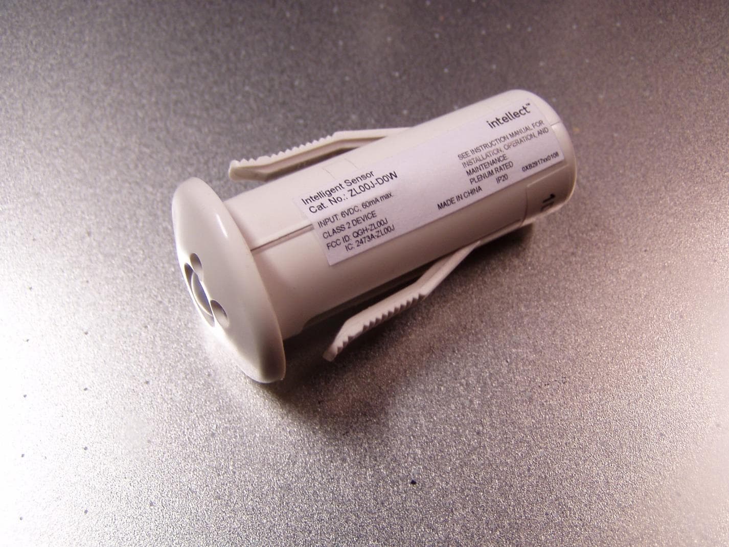
QGH-ZL00J
Apr 07, 2020ZL00J-D0W Intellect Sensor Head
Equipment Class
DTS - Digital Transmission System
QGH-ZBMG
Jan 02, 20200XB1803 Module
Equipment Class
DTS - Digital Transmission System