QGH-RZC0PWireless Lighting Control
Leviton Manufacturing Co., Inc.
Click to zoom
Application Details
- Equipment Class
- DXX - Part 15 Low Power Communication Device Transmitter
- Date of Grant
- Oct 02, 2007
- Application Purpose
- Original Equipment
- Date of Application
- Oct 02, 2007
- Equipment Note
- Wireless Lighting Control
- Frequency Range
- 908.42000000 - 908.42000000
- Country
- United States
Documents & Files
Document Text
Text extracted from the exhibit documents filed with the FCC. Open a document above to read the original.
Users Manual
Plug-In Serial Interface Module Cat. No. RZCØP Rated: 120VAC, 60Hz INStallatIoN INStRuCtIoNS DI-000-RZC0P-00A-X3 INtRoDuCtIoN Leviton’s Vizia TM RF components are designed to communicate with each other via Radio Frequency (RF) to provide remote control of your lighting. Using RF technology allows Leviton to provide the greatest signal integrity possible. Each module in Leviton’s Vizia TM RF component line is a Z-Wave TM enabled device. In a Z-Wave TM network, each device is designed to act as a router. These routers will re-transmit the RF signal from one device to another until the intended device is reached. This ensures that the signal is received by its intended device by routing the signal around obstacles and radio dead spots. The Plug-in Serial Interface Module is compatible with any Z-Wave™ enabled network, regardless of the manufacturer and can also be used with other devices displaying the Z-Wave™ logo. CautIoN: Remember to exercise good common sense when using the Timer features of your remote, especially when scheduling unattended devices. There can be some unexpected consequences if not used with care. For example, an empty coffee pot can be remotely turned on. If that should happen, your coffee pot could be damaged from overheating. If an electric heater is turned on by remote control while clothing is draped over it, a fire could result. Including Plug-In Serial Interface Module into Z-Wave tM Network: Step 3 attaching Plug-In Serial Interface Module to Wall Receptacle: Step 2 attaching Serial-RS232 Cable or HaI Cable to Plug-In Serial Interface Module: Step 1 NotE: In order to use your Vizia TM Plug-In Serial Interface Module in a Z-Wave TM network, it must be Included into the network using a Primary Programmer/Remote, such as Leviton’s Cat. No., RZCPG. Before Including your module, please refer to the Primary Programmer/Remote instruction sheet for complete information. Refer to Step 3 for further details. NotE: Use check boxes when Steps are completed. INStallING YouR INtERFaCE MoDulE RS232 cable to CPU HAI cable to HAI controller RS232 cable to Interface Module HAI cable to Interface Module OR WaRNINGS aND CautIoNS: • To be installed and/or used in accordance with appropriate electrical codes and regulations. • If you are unsure about any part of these instructions, consult a qualified electrician. WaRNINGS aND CautIoNS: • Save this instruction sheet. It contains important technical data along with testing and troubleshooting information which will be useful after installation is complete. • RS232 - ASCII • Scene capable • Two way communication • RF reliability • Ease of installation – No new wiring • Compatible with other Z-Wave™ enabled devices NotE: This product requires the use of third party software to function, along with a relatively high level of programming skill. FEatuRES Step 3 cont’d Programming Button 1 ON 2 ON 3 ON 4 ON OFF OFF OFF OFF Programmer/Remote Cat. No. RZCPG Center Button Menu Button Compatible withenabled products! TM NotES: • If using a non-Leviton Programmer/Remote, refer to the Programmer/Remote instruction sheet. • Plug-In Serial Interface Modules included into a Z-Wave TM network must be updated after you have included all other devices. a) If using a Leviton Z-Wave TM Programmer/ Remote, Cat. No. RZCPG, press the Menu button and scroll down to System Setup. Press the center button to select System Setup Menu. Press the center button to select Network. Press the center button to <Include Node>. B) If using RZCPG Programmer/Remote, you will be prompted to prepare device for inclusion. To do this you must put the Plug-In Serial Interface Module into programming mode. C) To access Program mode, press and hold programming button until the LED turns Amber. You are now in Programming mode. NotE: If the LED on the Plug-In Serial Interface Module turns solid Red while including, there has been a communication error. D) While standing close to the Plug-In Serial Interface Module (approximately 2-5 ft.), press the center button on the Programmer/Remote to <Include> device in the network. NotE: Only one device may be included at any time. E) The Primary Programmer/Remote will assign a Home ID, Node ID, and Name for this device. NotE: This information will be stored in the Programmer/Remote to be used for future reference. NotE: You may name or edit the node of this device at this time. F) the Plug-In Serial Interface Module is now installed in the network. G) After all devices are included into the network, the Plug-In Serial Interface Module must be updated to allow proper network function. To update Plug-In Serial Interface Module proceed as follows: • If using a non-Leviton Programmer/ Remote, refer to the Programmer/ Remote instruction sheet for updating Plug-In Serial Interface Module. • If using Leviton Z-Wave TM Programmer/ Remote, Cat. No. RZCPG, press the Menu button and scroll down to System Setup. Press the center button to select System Setup Menu. Press the center button to select Network. Press the center button to select Update "cntrl". When prompted, press button on the Plug-In Serial Interface Module. • Wait until the RZCPG Programmer/ Remote confirms completion. Update is done. NotE: If the Plug-In Serial Interface Module has been successfully Included in the network and the user tries to Include it again without first excluding it from the network, the controller will retain the first node ID it had received and ignore the second. • Attach RS232 cable to Plug- In Serial Interface Module and CPU. oR Attach HAI cable to Plug-In Serial Interface Module and HAI controller. • Plug the Plug-in Serial Interface Module into wall receptacle. Verify that receptacle is live. If controlled by a wall switch, the switch must be kept oN at all times. lIMItED 5 YEaR WaRRaNtY aND EXCluSIoNS Leviton warrants to the original consumer purchaser and not for the benefit of anyone else that this product at the time of its sale by Leviton is free of de…
Text truncated - open the document above for the full version.
Test Report
Underwriters Laboratories Inc. A not-for-profit organization dedicated 1285 Walt Whitman Rd. to public safety and committed to Melville, NY 11747 quality service for over 100 years Tel: (631) 271-6200 Fax: (631)439-6095 Underwriters Laboratories Inc. 1285 Walt Whitman Rd. Melville, NY 11747 www.ul.com/emc (631) 271-6200 Job Number: 07ME03926 File Number: MC15211 Date: 20 July 2007 Revision Date: 11 Sept. 2007 Model: RZC0P FCC ID: QGH-RZC0P Electromagnetic Compatibility Test Report For LEVITON MFG CO INC Copyright 2007 Underwriters Laboratories Inc. Underwriters Laboratories Inc. authorizes the above-named company to reproduce this Report provided it is reproduced in its entirety. Job Number: 07ME03926 File Number: MC15211 Page 2 of 50 Model Number: RZC0P Client Name: Leviton MFG. Co. Inc. FCC ID: QGH-RZC0P Underwriters Laboratories Inc. 1285 Walt Whitman Rd. Melville, New York 11747 USA Tel.: 631 271-6200 Fax: 631 439-6095 Rev. No 1.0 EMC Report 2007 Test Report Details Tests Performed By: Underwriters Laboratories Inc. 1285 Walt Whitman Rd. Melville, NY 11747 Tests Performed For: LEVITON MFG CO INC 59-25 LITTLE NECK PKY LITTLE NECK, NY 11362 Applicant Contact: Mr. P Patel Title: Not Provided Phone: (718) 281- 6574 Fax: (718) 281-6419 E-mail: [email protected] Test Report Date: 20 July 2007 Revision Date: 11 Sept. 2007 Product Type: Serial Interface Module Product standards FCC Part 15, Subpart C, 15.249 Model Number: RZC0P Sample Serial Number: Prototype EUT Category: Transceiver Testing Start Date: 01 Mar 2007 Date Testing Complete: 24 July 2007 Overall Results: Compliant Underwriters Laboratories Inc. reports apply only to the specific samples tested under stated test conditions. All samples tested were in good operating condition throughout the entire test program. It is the manufacturer's responsibility to assure that additional production units of this model are manufactured with identical electrical and mechanical components. Underwriters Laboratories Inc. shall have no liability for any deductions, inferences or generalizations drawn by the client or others from Underwriters Laboratories Inc. issued reports. This report shall not be used to claim, constitute or imply product certification, approval, or endorsement by NVLAP, A2LA, or any agency of the US government. This report may contain test results that are not covered by the NVLAP or A2LA accreditation. The scope of accreditation is limited to the specific tests that are listed on the NVLAP and/or A2LA websites referenced at the end of this report. Job Number: 07ME03926 File Number: MC15211 Page 3 of 50 Model Number: RZC0P Client Name: Leviton MFG. Co. Inc. FCC ID: QGH-RZC0P Underwriters Laboratories Inc. 1285 Walt Whitman Rd. Melville, New York 11747 USA Tel.: 631 271-6200 Fax: 631 439-6095 Rev. No 1.0 EMC Report 2007 Report Directory 1.0 G E N E R A L - Product Description...............................................................................................4 1.1 Equipment Description........................................................................................................................4 1.2 Equipment Marking Plate....................................................................................................................4 1.3 Device Configuration During Test.........................................................................................................5 1.3.1 Equipment Used During Test:..........................................................................................................5 1.3.2 Input/Output Ports:..........................................................................................................................5 1.3.3 EUT Internal Operating Frequencies:...............................................................................................6 1.3.4 Power Interface:.............................................................................................................................6 1.4 Block Diagram:...................................................................................................................................7 1.5 EUT Operation Modes........................................................................................................................7 1.6 EUT Configurations.............................................................................................................................7 2.0 Results Summary...............................................................................................................................8 2.1 Reference Standards..........................................................................................................................8 2.2 Results Summary...............................................................................................................................8 2.3 Deviations from standard test methods.................................................................................................9 2.4 Device Modifications Necessary for Compliance...................................................................................9 3.0 Calibration of Equipment Used for Measurement.......................................................................10 4.0 EMISSIONS TEST RESULTS...........................................................................................................11 4.1 Test Conditions and Results– MAINS TERMINAL – CONDUCTED EMISSIONS........................12 4.2 Test Conditions and Results– RADIATED EMISSIONS................................................................28 4.3 Test Conditions and Results: Supply Voltage Variation Versus Transmit Output Power............36 4.3.1 Test Conditions and Results: Frequency Stability..........................................................................39 4.4 Test Conditions and Results: Transmission On Time (Duty Cycle) Paragraph 15.35..................40 4.4 Test Conditions and Result…
Text truncated - open the document above for the full version.
Test Setup Photos
Conducted Emissions Radiated Emissions 30-1000MHz Radiated Emissions 1-10GHz Duty Cycle Occupied Bandwidth
Contact Information
Applicant
Frank Tse(Manager)
Technical Contact
Leviton MFG. Co. IncParimal Patel
718-281-6574
59-25 Little Neck Parkway · Little Neck, New York · United States
Non-Technical Contact
Leviton MFG. Co. IncFrank Tse
[email protected]718-281-2591
Test Firm
UL LLCBob Delisi
Technical Specifications
| # | Rule Parts | Frequency Range | Power Output |
|---|---|---|---|
| 1 | 15C | 908.42 MHz - 908.42 MHz | 50.00 µW |
Other Applications from Leviton Manufacturing Co., Inc.

QGH-B167601
Jun 25, 2020Lumina Wall Dimmer and Wireless Load Control Dimmer
Equipment Class
DTS - Digital Transmission System
QGH-B167602
Jun 25, 2020Lumina RF Wall Switch and Wireless Load Controller
Equipment Class
DTS - Digital Transmission System
QGH-PVDIM
Apr 07, 2020O5C04-IDW, O5C20-MDW, 06C04-IDW, 06C20-MDW, V6C04-IDW, V6C20-MDW
Equipment Class
DTS - Digital Transmission System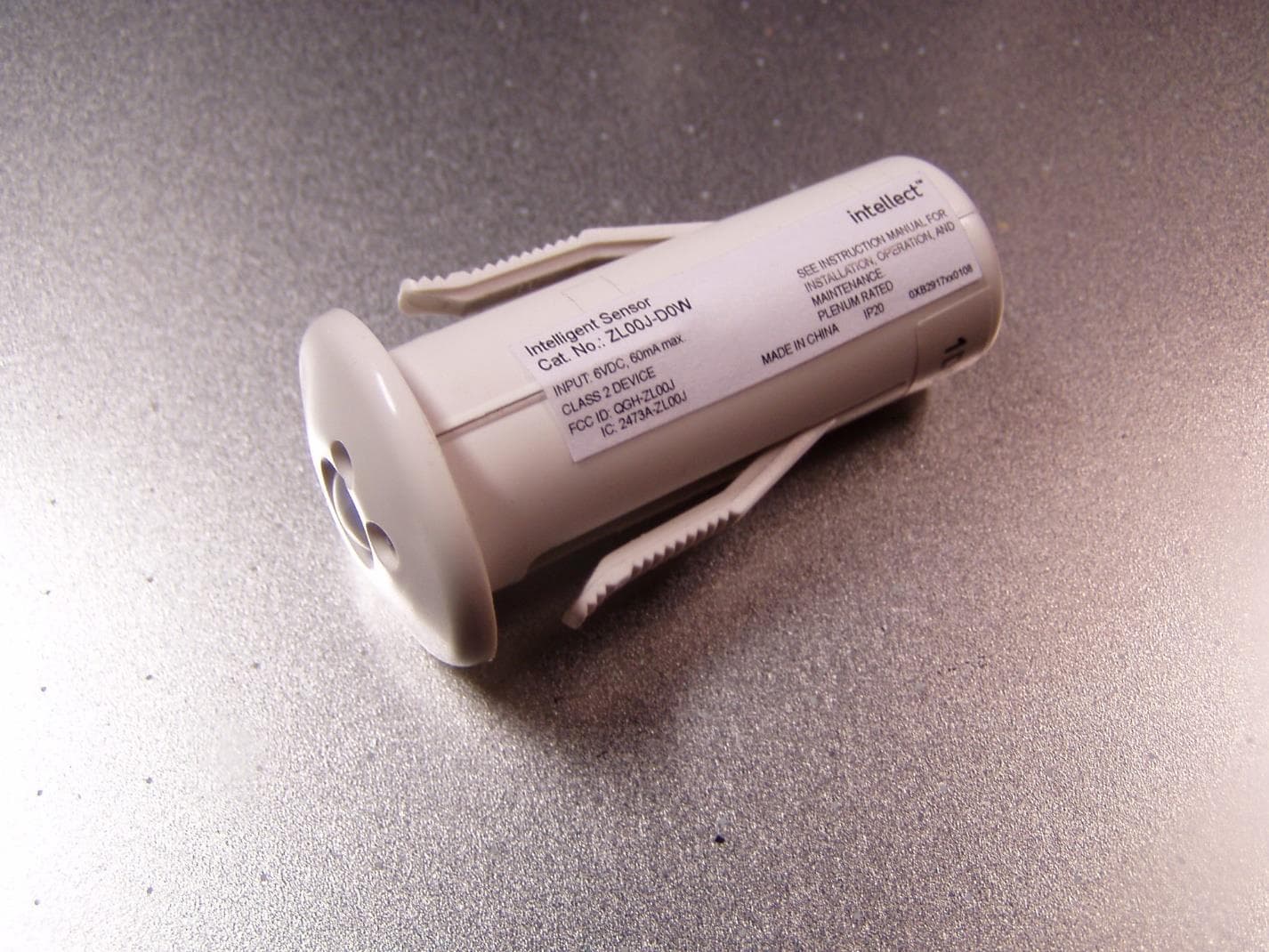
QGH-ZL00J
Apr 07, 2020ZL00J-D0W Intellect Sensor Head
Equipment Class
DTS - Digital Transmission System
QGH-ZBMG
Jan 02, 20200XB1803 Module
Equipment Class
DTS - Digital Transmission System