QGH-RZE06RF Dimmer
Leviton Manufacturing Co., Inc.
Click to zoom
Application Details
- Equipment Class
- DXX - Part 15 Low Power Communication Device Transmitter
- Date of Grant
- Jan 24, 2007
- Application Purpose
- Original Equipment
- Date of Application
- Jan 24, 2007
- Equipment Note
- RF Dimmer
- Frequency Range
- 908.42000000 - 908.42000000
- Country
- United States
Documents & Files
Document Text
Text extracted from the exhibit documents filed with the FCC. Open a document above to read the original.
Users Manual
Single Pole (One location) or 3-Way (Multi-location) Electronic Low-Voltage Dimmer (Lighted) Cat. No. RZEØ6-1L, 600W 120VAC, 60Hz INSTALLATION INSTRUCTIONS WARNINGS AND CAUTIONS: • To be installed and/or used in accordance with appropriate electrical codes and regulations. • If you are unsure about any part of these instructions, consult a qualified electrician. • To avoid overheating and possible damage to this device and other equipment, do not install to control a receptacle, fluorescent lighting, a motor- or a transformer-operated appliance. • Use with electronic low-voltage transformers only. Do Not use to control a magnetic low-voltage transformer. Use a Leviton magnetic low-voltage dimmer to control magnetic low-voltage transformers. • This dimmer provides protection from overheating. An excessive load applied to the dimmer will cause the dimmer to overheat. The excess load must be removed to resume proper operation. • Vizia™ RF dimmers are not compatible with standard 3-way or 4-way switches. They must be used with compatible Vizia™ remotes or Vizia™ RF controllers for multi-location dimming. • Use only one (1) Vizia™ RF dimmer in a multi-location circuit with up to 9 Vizia™ coordinating remotes without LEDs or Vizia™ RF controllers. WARNINGS AND CAUTIONS: • Lighting fixture and dimmer must be grounded. • This dimmer must be installed in a wall box with a neutral connection. • Consult fixture manufacturer to determine if their solid state transformers can be dimmed. • Total minimum load must exceed 40W. • Dimmer may feel warm to the touch during normal operation. • Recommended minimum wall box depth is 2-1/2". • Maximum wire length from dimmer to all installed remotes cannot exceed 300 ft (90 m). • Disconnect power at circuit breaker or fuse when servicing, installing or removing fixture. • Use this device only with copper or copper clad wire. With aluminum wire use only devices marked CO/ALR or CU/AL. IMPORTANT : For 3-Way applications, note that one of the screw terminals from the old switch being removed will usually be a different color (Black) or labeled Common. Tag that wire with electrical tape and identify as the common (Line or Load) in both the dimmer wall box and remote wall box. For non-standard wiring applications, refer to Wire Nut and Connector Size Chart 1 - #12 w/ 1 to 3 #14, #16 or #18 2 - #12 w/ 1 or 2 #16 or #18 1 - #14 w/ 1 to 4 #16 or #18 2 - #14 w/ 1 to 3 #16 or #18 WIRE CONNECTOR / # OF COND. COMBINATION CHART DI-000-RZE06-00A-X0 MAXIMUM LOAD PER DIMMER FOR MULTI-DEVICE Cat. No. VZEØ6 Single 600W Two Devices 500W More than 2 Devices 400W Tools needed to install your Dimmer: Slotted/Phillips Screwdriver Electrical Tape Pliers Pencil Cutters Ruler When installing more than one dimmer in the same location, the side sections of the mounting strap must be removed. Use pliers to carefully bend side sections back and forth until they break off. The side sections dissipate heat, so removing them sometimes requires a derating of the dimmer’s capacity (refer to chart) . Remove all inner side sections Bend back and forth to remove side section ����� ����� ����� ����� ����� ����� ����� ����� ����� ����� ����� ����� Cut (if necessary) 5/8" (1.6 cm) Strip Gage (measure bare wire here) Preparing and connecting wires: Pull off pre-cut insulation from dimmer leads. Make sure that the ends of the wires from the wall box are straight (cut if necessary) . Remove insulation from each wire in the wall box as shown: • For Single-Pole Application, go to Step 4a. • For 3-Way Coordinating Remote (no LEDs) Application, go to Step 4b. Dimmer Insulating Label Black Primary Side Electronic Low-Voltage Transformer Hot (Black)Black Line 120VAC, 60Hz Neutral (White) RedYellow/Red White White Green Ground WIRING DIMMER: Connect wires per WIRING DIAGRAM as follows: • Green or bare copper wire in wall box to Green dimmer lead. • Line Hot wall box wire to Black dimmer lead. • Load wall box wire to Red dimmer lead. • Line Neutral wall box wire to White dimmer lead. • Yellow/Red wire should have Red insulation label affixed. NOTE: If insulating label is not affixed to Yellow/Red dimmer lead, use electrical tape to cover. • Proceed to Step 5. Hot (Black) Neutral (White) Dimmer Coordinating Remote (no LEDs) YL/RD Yellow/Red RD White Red Black Black BKWH White Line 120VAC, 60Hz Green Ground Green Ground Electronic Low-Voltage Transformer Primary Side (unused) (unused ) WIRING DIMMER: Connect wires per WIRING DIAGRAM as follows: NOTE: The dimmer must be installed in a wall box that has a Line Hot connection. NOTE: Maximum wire length from dimmer to all installed remotes cannot exceed 300 ft (90 m). • Green or bare copper wire in wall box to Green dimmer lead. • Line Hot (common) wall box wire identified (tagged) when removing old switch to Black dimmer lead. • First Traveler wall box wire to Red dimmer lead (note wire color). • Remove Red insulating label from Yellow/Red dimmer lead. • Second Traveler wall box wire to Yellow/Red dimmer lead (note wire color). This traveler from the dimmer must go to the terminal screw on the remote marked "YL/RD". • Line Neutral wall box wire to White dimmer lead. WIRING COORDINATING REMOTE: Connect wires per WIRING DIAGRAM as follows: NOTE: "BK" and "RD" terminals on coordinating remote are unused. Tighten both screws. NOTE: Maximum wire length from dimmer to last remote is 300 ft (90 m). • Green or bare copper wire in wall box to Green terminal screw. • Load wall box wire identified (tagged) when removing old switch to First Traveler (note color as above) . • Second Traveler wall box wire (note color as above) to terminal screw marked "YL/RD". This traveler from the remote must go to the Yellow/Red dimmer lead. • Remove White insulating label from terminal screw marked "WH". • Line Neutral wall box wire to terminal screw marked "WH". • Proceed to Step 5. INSTALLING YOUR DIMMER NOTE: Use check boxes when Steps are completed. 2 4 3 1 2 4 1 5 3 Single Pole 1. Line (…
Text truncated - open the document above for the full version.
Test Report
Underwriters Laboratories Inc. A not-for-profit organization dedicated 1285 Walt Whitman Rd. to public safety and committed to Melville, NY 11747 quality service for over 100 years Tel: (631) 271-6200 Fax: (631)439-6095 Underwriters Laboratories Inc. 1285 Walt Whitman Rd. Melville, NY 11747 www.ul.com/emc 631-271-6200 Project: 06CA21437 File: MC15211 Date: 10/16/2006 Model: RZEO6 FCC ID: QGH-RZE06 Electromagnetic Compatibility Test Report For LEVITON MFG CO INC Copyright 2005 Underwriters Laboratories Inc. Underwriters Laboratories Inc. authorizes the above-named company to reproduce this Report provided it is reproduced in its entirety. Only those products bearing the UL Mark should be considered as being covered by UL. Project Number: 06CA21437 File Number MC15211 Page 2 of 52 Model Number: RZE06 FCC ID: QGH-RZE06 Underwriters Laboratories Inc. 1285 Walt Whitman Rd. Melville, New York 11747 USA Tel.: 631 271-6200 Fax: 631 439-6095 Rev. No 1.0 EMC Report Generator Trial Version 1.1 Feb-06. Only those products bearing the UL Mark should be considered as being covered by UL. Test Report Details Tests Performed By: Underwriters Laboratories Inc. 1285 Walt Whitman Rd. Melville, NY 11747 Tests Performed For: LEVITON MFG CO INC 59-25 LITTLE NECK PKY LITTLE NECK, NY 11362 Applicant Contact: Mr. P Patel Contact Signature*: Title: Not Provided Phone: (718) 281- 6940 Fax: (718) 281- 6419 E-mail: [email protected] Test Report Date: 10/16/2006 Product Type: DIMMER Product standards FCC Part 15, Subpart C, 15.249 Model Number: RZEO6 Sample Serial Number: Prototype Sample Tag Number: 0788592 Sample Receive Date: 5/9/2006 Lab Tracking Number: 06MEL4109 EUT Category: Transceiver Testing Start Date: 5/9/2006 Date Testing Complete: 9/5/2006 Overall Results: Pass Underwriters Laboratories Inc. reports apply only to the specific samples tested under stated test conditions. All samples tested were in good operating condition throughout the entire test program. It is the manufacturer's responsibility to assure that additional production units of this model are manufactured with identical electrical and mechanical components. Underwriters Laboratories Inc. shall have no liability for any deductions, inferences or generalizations drawn by the client or others from Underwriters Laboratories Inc. issued reports. This report shall not be used to claim, constitute or imply product certification, approval, or endorsement by NVLAP, A2LA, or any agency of the US government. This report may contain test results that are not covered by the NVLAP or A2LA accreditation. The scope of accreditation is limited to the specific tests that are listed on the NVLAP and/or A2LA websites referenced at the end of this report. *Signature required for products covered by FCC Declaration of Conformity or Verification in accordance with record retention requirements in FCC Rules 2.955(x) or 2.1057(x). Project Number: 06CA21437 File Number MC15211 Page 3 of 52 Model Number: RZE06 FCC ID: QGH-RZE06 Underwriters Laboratories Inc. 1285 Walt Whitman Rd. Melville, New York 11747 USA Tel.: 631 271-6200 Fax: 631 439-6095 Rev. No 1.0 EMC Report Generator Trial Version 1.1 Feb-06. Only those products bearing the UL Mark should be considered as being covered by UL. Report Directory 1.0 G E N E R A L - Product Description.........................................................................................4 1.1 Device Configuration During Test........................................................................................................5 1.2 EUT Operation Modes:.........................................................................................................................6 1.3 EUT Configuration Modes:...................................................................................................................6 1.4 Block Diagram:......................................................................................................................................7 1.5 Deviations from standard test methods................................................................................................7 1.6 Device Modifications Necessary for Compliance.................................................................................7 1.7 Test Summary.......................................................................................................................................8 2.0 Conclusion:......................................................................................................................................9 3.0 FCC Labeling Information..........................................................................................................10 3.1 Identification.........................................................................................................................................10 3.2 Compliance information........................................................................................................................10 3.3 Labeling...............................................................................................................................................11 3.4 User information...................................................................................................................................13 4.0 Calibration of Equipment Used for Measurement................................................................13 5.0 EMISSIONS TEST REGULATIONS............................................................................................14 Conducted Emissions Test – Mains & I/O Lines............................................................................................15 Radiated Emissions Test...............................................................................................................................25 Occupied Bandwidth..................................................................................................................…
Text truncated - open the document above for the full version.
Test Setup Photos
Model RZE06 Conducted Emissions Test Set-Up Model RZE06 – Front View 30-1000MHz Model RZE06 – Rear View 30-1000MHz Radiated Emissions Test Set-up Model RZE06 – Front View 1-10GHz Model RZE06 – Rear View 1-10GHz Radiated Emissions Test Set-up Model RZE06 Occupied Bandwidth Test Set-Up Model RZE06 Duty Cycle Test Set-Up
Contact Information
Applicant
Frank Tse(Manager)
Technical Contact
Leviton MFG Co. Inc.Parimal Patel
[email protected]718-281-6574
59-25 Little Neck Parkway · Little Neck, New York · United States
Non-Technical Contact
Leviton MFG Co. Inc.Frank Tse
[email protected]718-281-2591
Test Firm
UL LLCBob Delisi
Technical Specifications
| # | Rule Parts | Frequency Range | Power Output | Emission |
|---|---|---|---|---|
| 1 | 15C | 908.42 MHz - 908.42 MHz | 20.00 µW | F3D |
Other Applications from Leviton Manufacturing Co., Inc.

QGH-B167601
Jun 25, 2020Lumina Wall Dimmer and Wireless Load Control Dimmer
Equipment Class
DTS - Digital Transmission System
QGH-B167602
Jun 25, 2020Lumina RF Wall Switch and Wireless Load Controller
Equipment Class
DTS - Digital Transmission System
QGH-PVDIM
Apr 07, 2020O5C04-IDW, O5C20-MDW, 06C04-IDW, 06C20-MDW, V6C04-IDW, V6C20-MDW
Equipment Class
DTS - Digital Transmission System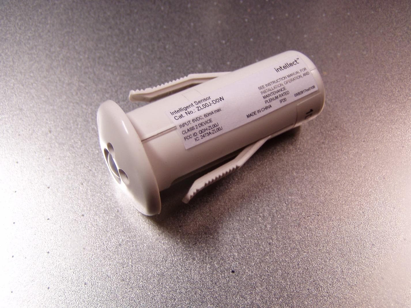
QGH-ZL00J
Apr 07, 2020ZL00J-D0W Intellect Sensor Head
Equipment Class
DTS - Digital Transmission System
QGH-ZBMG
Jan 02, 20200XB1803 Module
Equipment Class
DTS - Digital Transmission System