QGH-RZP03Plug-In Appliance Module
Leviton Manufacturing Co., Inc.
Click to zoom
Application Details
- Equipment Class
- DXT - Part 15 Low Power Transceiver, Rx Verified
- Date of Grant
- Dec 27, 2005
- Application Purpose
- Original Equipment
- Date of Application
- Dec 27, 2005
- Equipment Note
- Plug-In Appliance Module
- Frequency Range
- 908.42000000 - 908.42000000
- Country
- United States
Documents & Files
Document Text
Text extracted from the exhibit documents filed with the FCC. Open a document above to read the original.
Users Manual
PRELIMINARY NOTES: • Some non-Leviton programmers may be built on older Z-Wave™ libraries which may require your module to be replicated in the network instead of enrolling it to the network. First try to enroll module in your network. If it is unable to enroll, refer to the Primary Controller/ Programmer instruction sheet for replicating a device. A) When first powering Plug-In Dimmer Module, there is a 30 second enrollmemnt access period before your module times out. Within 30 seconds, depress and hold the programming button located on the front of the module until the LED beneath the button turns to solid Amber (approx. 10 seconds). NOTE: If Plug-In Dimmer Module times out, unplug module from receptacle and plug back in. The 30 second enrollmemnt access period will then begin again. B) After LED turns solid Amber, release the button. The LED will start to blink Amber. The unit is now in the Enrollment/ Un-enrollment mode. If necessary to exit the Enrollment/Un-enrollment mode, press the programming button. RF Plug-In Dimmer Module Cat. No. RZPØ3-1LW Rated: 120VAC, 60Hz Incandescent: 300W max., 60W min. INSTALLATION INSTRUCTIONS DI-000-RZP03-00A-X1 INTRODUCTION Leviton’s Vizia TM RF components are designed to communicate with each other via Radio Frequency (RF) to provide remote control of your lighting. Using RF technology allows Leviton to provide the greatest signal integrity possible. Each module in Leviton’s Vizia TM RF component line is a Z-wave TM enabled device. In a Z-wave TM network, each device is designed to act as a router. These routers will re-transmit the RF signal from one device to another until the intended device is reached. This ensures that the signal is received by its intended device by routing the signal around obstacles and radio dead spots. The RZPØ3 Plug-in Dimmer Module is fully compatible with any Z-wave™ enabled network, regardless of the manufacturer and can also be used with other devices displaying the Z-wave™ logo. CAUTION: Remember to exercise good common sense when using the Home Automation features of your remote, especially when scheduling unattended devices. There can be some unexpected consequences if not used with care. For example, an empty coffee pot can be remotely turned on. If that should happen, your coffee pot could be damaged from overheating. If an electric heater is turned on by remote control while clothing is draped over it, a fire could result. DO NOT USE the remote for the control of high power heating appliances such as portable heaters. This device will not control lighting that is used with electronic low-voltage and high frequency power supply transformers, nor high pressure discharge lamps (HID lighting). This includes mercury-vapor, sodium vapor and metal halide lamps. Enrolling Plug-In Dimmer Module in Network : Step 3 Attaching Plug-In Dimmer Module to Wall Receptacle: Step 2 • Plug the Plug-in Dimmer Module into wall receptacle. Verify that receptacle is live. If controlled by a wall switch, the switch must be kept ON at all times. Attaching Load to Plug-In Dimmer Module: Step 1 NOTE: In order to use your Vizia TM RF Module in a Z-wave TM network, it must be enrolled into the network using a Primary Programmer/Controller, such as Leviton’s Cat. No., RZCPG-1LG. Before enrolling your module, please refer to the Primary Programmer/ Controller instruction sheet for complete information. Refer to Step 3 for further details . • Locate lamp to be controlled by Plug-In Dimmer Module and ensure it is fully operational. Attach lamp plug into Plug-in Dimmer Module receptacle noting proper polarity of blades. NOTE: Use check boxes when Steps are completed. INSTALLING YOUR DIMMER MODULE C) If using a Leviton Z-wave TM Programmer/Controller, Cat. No. RZCPG, select the Menu Screen, then select Network and scroll down to the Enrollment Screen. D) While standing close to the module, select it to enroll it in the network. NOTE: Only one device may be enrolled at a time. DO NOT put multiple devices into Enrollment mode at any time. E) The Primary Programmer/ Controller will prompt you to chose a node ID number (Name) for this module. NOTE: Keep a record of the ID number (Name) associated to this module for future reference. F) After the module is enrolled, the Z-wave TM Programmer/Controller will give a confirmation message and the LED on the Plug-In Dimmer Module will turn green. G) The module is now installed in the network. NOTE: If the module has been successfully enrolled in the network and a user tries to enroll it again without first un-enrolling it from the network, the module will retain the first node ID it had received and ignore the second. WARNINGS AND CAUTIONS: • To be installed and/or used in accordance with appropriate electrical codes and regulations. • If you are unsure about any part of these instructions, consult a qualified electrician. • To redu ce the risk of overheating and possible damage to other equipment do not install to control a motor-operated appliance, fluorescent lighting fixture, or a transformer supplied appliance. WARNINGS AND CAUTIONS: • Unplug unit when servicing connected lighting fixtures. • Save this instruction sheet. It contains important technical data along with testing and troubleshooting information which will be useful after installation is complete. • Soft fade ON/OFF • Works with Z-wave TM compatible controllers • Scene capable • ON/OFF LED indicates status of load • Two way communication to provide status reporting to controllers • Manual ON capability at load • RF reliability • Ease of installation – No new wiring • Compatible with other Z-wave™ enabled devices FEATURES 1 ON 2 ON 3 ON 4 ON OF F OF F OF F OF F RZCPG-1LG Step 2 cont’d Step 3 cont’d Wall Receptacle Lamp plug RF Plug-In Dimmer Module NOTE: Programmer/Controller must be in close proximity to RF Plug-In Module when enrolling into network RZCPG Programmer/ Controller Programming and ON/OFF Button PRELIMINARY LIMITED 5 YEAR WARRA…
Text truncated - open the document above for the full version.
Cover Letter(s)
AHD EMC Lab, 92723 M152, Dowagiac, MI 49047, (269) 424-7014 FCC_Confident1.doc Request for CONFIDENTIALITY: Page 1 of 1 NVLAP ACCREDITED NARTE Certified Engineer Professional Engineer Federal Communications Commission August 5, 2005 Equipment Approval Services, P.O. Box 358315 Pittsburgh, PA 15251-5315 ELITE Electronic Engineering TCB Services 1516 Centre Circle Downers Grove, IL 60515-1082 Re: Request for exhibits to be kept confidential. FCC ID: QGH-RZP03 Gentlemen: Pursuant to 47CRF 0.459, Leviton Manufacturing Inc., and Twisthink LLC requests that these listed exhibits be held confidential. Circuit Block Diagram file names: EXB_CircuitBlockdiagramRZP03.pdf Theory/Description of Operation, file name: EXB_TechnicalDescRZP03.pdf Schematics file names: EXB_schematicPwrDimrPCBRZP03.pdf EXB_schematicRFPCBRZP03.pdf Leviton Manufacturing and Twisthink have invested considerable resources into developing this product. Having sections of Exhibit B, listed above, available to ‘competition’ would negate the advantage achieved in developing this product. Since this product type is a major product line for Leviton Manufacturing, not protecting the details of the design would result in a financial hardship for the company. The Federal Communications Commission will be notified, in writing, of any changes in the software/programming of the device that could affect the device’s RF characteristics. Your prompt consideration of this application for product certification will be greatly appreciated. Should you have any questions regarding the content of this report, kindly contact me. Sincerely, Ted Chaffee, Technical Lab Manager Narte Certified Engineer, #EMC-002025-NE tel/fax: 269. 424.7014 email: [email protected]
RF Exposure Info
Test report #0500786DIMF FCC 15.249 for RZP03 FCC ID: QGH-RZP03 Tested May 11, 2005 AHD EMC Lab, 92723 M152, Dowagiac, MI 49047, (269) 424-7014 EXmisc_RFexpose.doc Misc. EXHIBIT: Page 1 of 1 MISC. EXHIBIT: RF EXPOSURE INFORMATION [2.1093(C)] The manufacturer and applicant: LEVITON MANUFACTURING, INC. 59-25 Little Neck Pkwy. Little Neck, NY 11362 Product: RF Plug-In Appliance Module. Model: RZP03 Applicable Rules: 47CFR Part 15.249 Pursuant to 47CFR Part 1.1307(b), 47CFR Part 2.1091(c), and 47CFR Part 2.1093(c) this transmitting device, compliant to 47CFR Part 15.249, is categorically excluded from evaluation regarding the Maximum Permissible Exposure of RF energy.
Test Report
Test report #0500786DIMF FCC 15.249 for RZP03 FCC ID: QGH-RZP03 Tested May 11, 2005 AHD EMC Lab, 92723 M152, Dowagiac, MI 49047, (269) 424-7014 EXE_TestRprt.doc EXHIBIT E: Page 1 of 18 EXHIBIT E: REPORT OF MEASUREMENTS [2.1033(B6)] Test Report for FCC ID: QGH-RZP03 FCC Part 2.1031, Part 15 Subpart C(15.249) Report #0500786DIMF Issued 06/24/05 908.42MHZ TRANSCEIVER MODEL RZP03 Prepared for: LEVITON MANUFACTURING CO., Inc. Little Neck PKWY Little Neck, NY 11362 Test Date(s): April 13, May 5,6,11, 2005 data recorded by Ted Chaffee, NCE Gordon L. Helm, NCE This report prepared by: Ted Chaffee, NCE Technical Manager/Test Engineer, AHD Test report #0500786DIMF FCC 15.249 for RZP03 FCC ID: QGH-RZP03 Tested May 11, 2005 AHD EMC Lab, 92723 M152, Dowagiac, MI 49047, (269) 424-7014 EXE_TestRprt.doc EXHIBIT E: Page 2 of 18 TABLE OF CONTENTS EXHIBIT E: Report of Measurements [2.1033(b6)] .....................................................................................1 TABLE OF CONTENTS.........................................................................................................................2 Statements Concerning this Report.......................................................................................................3 Manufacturer/Applicant [2.1033(b1)] ....................................................................................................4 Measurement/Test Site Facility & Equipment........................................................................................4 Test Site1 [2.948, 2.1033(b6)] ....................................................................................................4 Measurement Equipment Used [2.947(d), 15.31(b)] ....................................................................4 Test Site2 [2.948, 2.1033(b6)] ....................................................................................................5 Tested Configuration /Setup: [2.1033(b8)] ............................................................................................6 Support Equipment & Cabling .......................................................................................................6 Setup Diagram ...............................................................................................................................6 Summary of Results: .............................................................................................................................7 Changes made to achieve compliance..........................................................................................7 Standards Applied to Test: [2.1033(b6)]................................................................................................8 Test Methodology: [2.1033(b6)].............................................................................................................8 FORMULAS AND SAMPLE CALCULATIONS: ...........................................................................10 Test Data [2.1033(b6)].........................................................................................................................11 Relative Emission Level vs. Supply Voltage [15.31(e)] ...............................................................11 Modulation Characteristics ..........................................................................................................12 Occupied Bandwidth ....................................................................................................................12 Radiated Field Strength Measurements: [15.209, 15.249(a,d)] .................................................13 Out of Band Emissions [15.249(d)]..............................................................................................16 Line Conducted Measurements: [15.207(a)]...............................................................................17 Test report #0500786DIMF FCC 15.249 for RZP03 FCC ID: QGH-RZP03 Tested May 11, 2005 AHD EMC Lab, 92723 M152, Dowagiac, MI 49047, (269) 424-7014 EXE_TestRprt.doc EXHIBIT E: Page 3 of 18 Statements Concerning this Report NVLAP Accreditation: NVLAP Lab Code 200129-0 The scope of AHD accreditation is the conducted emissions, radiated emissions test methods of: IEC/CISPR 22: Limits and methods measurement of radio disturbance characteristics of information technology equipment. FCC Method – 47 CFT Part 15: . AS/NZS 3548: Electromagnetic Interference – Limits and Methods of Measurement of Information Technology Equipment. IEC61000-4-2 and Amend.1: ElectroStatic Discharge Immunity IEC61000-4-5: Surge Immunity Test Data: This test report contains data covered by the NVLAP accreditation. Subcontracted Testing: This report contains data recorded at the University of Michigan Radiation Laboratory. The University of Michigan test facility is located at 8501 Beck Road, Belleville, Michigan 48111. This test facility has been fully described and accepted by the FCC and Industry Canada. This facility was utilized to measure emissions occurring at frequencies greater than 6GHz. Test Traceability: The calibration of all measuring and test equipment and the measured data using this equipment are traceable to the National Institute for Standards and Technology (NIST). Limitations on results: The test results contained in this report relate only to the Item(s) tested. Any electrical or mechanical modification made to the test item subsequent to the test date shall invalidate the data presented in this report. Any electrical or mechanical modification made to the test item subsequent to this test date shall require an evaluation to verify continued compliance. Limitations on copying: This report shall not be reproduced, except in full, without the written approval of AHD. Limitations of the report: This report shall not be used to claim product endorsement by NVLAP, FCC, or any agency of the US Government. Statement of Test Results Uncertainty: Following the guidelines of NAMAS publication NIS81 and…
Text truncated - open the document above for the full version.
Contact Information
Applicant
Frank Tse(Manager)
Technical Contact
Twisthink, LLCBrent Bouws
[email protected]616-355-0469
130 Central Ave. · Holland, Michigan · United States
Non-Technical Contact
AHDTed N Chaffee
[email protected]269-424-7014
Test Firm
AHD (Amber Helm Development, L.C.)Gordon Helm
Technical Specifications
| # | Rule Parts | Frequency Range | Power Output |
|---|---|---|---|
| 1 | 15C | 908.42 MHz - 908.42 MHz | - |
Other Applications from Leviton Manufacturing Co., Inc.

QGH-B167601
Jun 25, 2020Lumina Wall Dimmer and Wireless Load Control Dimmer
Equipment Class
DTS - Digital Transmission System
QGH-B167602
Jun 25, 2020Lumina RF Wall Switch and Wireless Load Controller
Equipment Class
DTS - Digital Transmission System
QGH-PVDIM
Apr 07, 2020O5C04-IDW, O5C20-MDW, 06C04-IDW, 06C20-MDW, V6C04-IDW, V6C20-MDW
Equipment Class
DTS - Digital Transmission System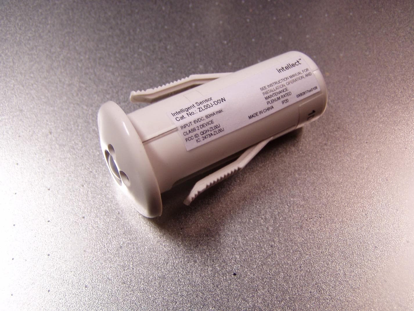
QGH-ZL00J
Apr 07, 2020ZL00J-D0W Intellect Sensor Head
Equipment Class
DTS - Digital Transmission System
QGH-ZBMG
Jan 02, 20200XB1803 Module
Equipment Class
DTS - Digital Transmission System