QGH-RZSD1In Wall Relay
Leviton Manufacturing Co., Inc.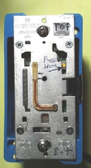
Click to zoom
Application Details
- Equipment Class
- DXT - Part 15 Low Power Transceiver, Rx Verified
- Date of Grant
- Apr 29, 2007
- Application Purpose
- Original Equipment
- Date of Application
- Apr 29, 2007
- Equipment Note
- In Wall Relay
- Frequency Range
- 908.42000000 - 908.42000000
- Country
- United States
Documents & Files
Document Text
Text extracted from the exhibit documents filed with the FCC. Open a document above to read the original.
Users Manual
B) If using RZCPG Programmer/Contoller, you will be prompted to place 1-scene controller into programming mode. C) To access Program mode, engage the air gap switch by gently pulling the bottom of the push pad until it lifts out of the frame and a click is heard (refer to figure). Wait 5 seconds and then press the push pad back into the frame and hold push pad until the LED flashes Amber. Release the push pad and the LED should blink Amber. You are now in Programming mode. NOTE: If the LED on the 1-scene controller turns solid Red while including, there has been a communication error. Refer to Troubleshooting section . D) While standing close to the 1-scene controller (approximately 2-5 ft.), press the center button to <Include> device in the network. NOTE: Only one device may be included at any time. E) The Primary Programmer/Controller will assign a node ID number (Name) for this device. NOTE: This ID number (Name) will be stored in the Programmer/Controller to be used for future reference. NOTE: You may name or edit the node of this device at this time. F) The 1-scene controller is now installed in the network . G) After all devices are included into the network, the controller must be updated to allow it to be associated with all devices in the network. To update controller proceed as follows: • If using a non-Leviton Programmer/Controller, refer to the Programmer/Controller instruction sheet for updating controller. • If using Leviton Z-Wave TM Programmer/Controller, Cat. No. RZCPG, press the Menu button and scroll down to System Setup. Press the center button to select System Setup Menu. Press the center button to select Network. Press the center button to select Update cntrl. Press rocker on the 1-scene controller. • Wait until the RZCPG Programmer/ Controller confirms completion. Update is done. NOTE: If the 1-scene controller has been successfully Included in the network and the user tries to Include it again without first excluding it from the network, the controller will retain the first node ID it had received and ignore the second. WARNINGS AND CAUTIONS: • ON/OFF LED shows status of remote load control. • To be installed and/or used in accordance with appropriate electrical codes and regulations. • If you are unsure about any part of these instructions, consult a qualified electrician. • Vizia™ RF RZCS1 remote does not control the load, but provides 3-way or 4-way applications to operate with Vizia TM RF switches. • Recommended minimum wall box depth is 2-1/2". WARNINGS AND CAUTIONS: • No traveler wires are needed. Remote controls via radio frequency (RF) technology. • Can call one (1) scene ON/OFF with advanced Programmer/Controller (see RZCPG). • Disconnect power at circuit breaker or fuse when servicing, installing or removing fixture. • Use this device only with copper or copper clad wire. With aluminum wire use only devices marked CO/ALR or CU/AL. 1-Scene Controller/ Matching Switch Remote Cat. No. RZCS1 120VAC, 60Hz INSTALLATION INSTRUCTIONS DI-000-RZCS1-00A-X3 Tools needed to install your 1-Scene Controller: Slotted/Phillips Screwdriver Electrical Tape Pliers Pencil Cutters Ruler Changing the color of your 1-Scene Controller: Your 1-scene controller includes three color options. The controller ships with the White frame attached. To ch ange color of frame, proceed as follows: Line up tabs and press in side to attach Push in side at tab to release INSTALLING YOUR 1-SCENE CONTROLLER NOTE: Use check boxes when Steps are completed. ����� ����� ����� ����� ����� ����� ����� ����� ����� ����� ����� ����� WARNING: TO AVOID FIRE SHOCK OR DEATH; TURN OFF POWER at circuit breaker or fuse and test that power is off before wiring! Step 1 Step 3 Compatible withenabled products! TM IMPORTANT : For 3-Way applications, note that only one (1) switch can be controlled by the 1-scene controller. Preparing and connecting wires: This 1-scene controller can be wired using side wire terminal screws or through backwire openings. Choose appropriate wire stripping specifications accordingly. • Make sure that the ends of the wires from the wall box are straight (cut if necessary). 5/8" (1.6 cm) Strip Gage (measure bare wire here) Cut (if necessary) Side Wire Connection Side wire terminals accept #14 AWG solid wire copper only. Back Wire (either hole may be used) Back wire openings use #14-12 AWG solid wire copper only. WIRING SWITCH: Connect wires per WIRING DIAGRAM as follows: • Green or bare copper wire in wall box to Green terminal screw. • Line Hot wall box wire to terminal screw marked "BK". • Line Neutral wall box wire to terminal screw marked "WH". • Proceed to Step 5. • Position all wires to provide room in outlet wall box for device. • Ensure that the word “TOP” is facing up on device strap. • Partially screw in mounting screws in wall box mounting holes. NOTE: Dress wires with a bend as shown in diagram in order to relieve stress when mounting device. • Restore power at circuit breaker or fuse. • LED should turn ON. If LED does not turn ON, refer to the TROUBLESHOOTING section. Testing your 1-Scene Controller prior to mounting in wall box: Step 5 Step 6 cont'd Cat. No. RZCPG 1 ON 2 ON 3 ON 4 ON OFF OFF OFF OFF Menu Button Center Button Gently lift bottom of push pad out Wiring Application: Hot (Black) Neutral (White) Line 120VAC, 60Hz BKWH Green Ground 1-Scene Controller Step 4 2 4 3 1 2 4 1 5 3 Single Pole 1. Line (Hot) 2. Neutral 3. Ground 4. Load 3-Way 1. Line or Load (see important instruction) 2. Neutral 3. Ground 4. First Traveler – note color 5. Second Traveler – note color Identifying your wiring application (most common): NOTE: If the wiring in your wall box does not resemble any of these configurations, consult a qualified electrician. Step 2 INTRODUCTION Leviton’s Vizia TM RF components are designed to communicate with each other via Radio Frequency (RF) to provide remote control of your lighting. Using RF technology allows Leviton to provide the greatest signal integrity p…
Text truncated - open the document above for the full version.
Users Manual
B) If using RZCPG Programmer/Contoller, you will be prompted to place 1-zone controller into programming mode. C) To access Program mode, engage the air gap switch by gently pulling the bottom of the push pad until it lifts out of the frame and a click is heard (refer to figure). Wait 5 seconds and then press the push pad back into the frame and hold push pad until the LED flashes Amber. Release the push pad and the LED should blink Amber. You are now in Programming mode. NOTE: If the LED on the 1-zone controller turns solid Red while including, there has been a communication error. Refer to Troubleshooting section . D) While standing close to the 1-zone controller (approximately 2-5 ft.), press the center button to <Include> device in the network. NOTE: Only one device may be included at any time. E) The Primary Programmer/Controller will assign a node ID number (Name) for this device. NOTE: This ID number (Name) will be stored in the Programmer/Controller to be used for future reference. NOTE: You may name or edit the node of this device at this time. F) The 1-zone controller is now installed in the network . G) After all devices are included into the network, the controller must be updated to allow it to be associated with all devices in the network. To update controller proceed as follows: • If using a non-Leviton Programmer/Controller, refer to the Programmer/Controller instruction sheet for updating controller. • If using Leviton Z-Wave TM Programmer/Controller, Cat. No. RZCPG, press the Menu button and scroll down to System Setup. Press the center button to select System Setup Menu. Press the center button to select Network. Press the center button to select Update cntrl. Press rocker on the 1-zone dimming controller. • Wait until the RZCPG Programmer/ Controller confirms completion. Update is done. NOTE: If the 1-zone controller has been successfully Included in the network and the user tries to Include it again without first excluding it from the network, the controller will retain the first node ID it had received and ignore the second. WARNINGS AND CAUTIONS: • ON/OFF LED shows status of remote load control. • To be installed and/or used in accordance with appropriate electrical codes and regulations. • If you are unsure about any part of these instructions, consult a qualified electrician. • Vizia™ RF RZCZ1 remote does not control the load, but provides 3-way or 4-way applications to operate with Vizia TM RF switches. • Recommended minimum wall box depth is 2-1/2". WARNINGS AND CAUTIONS: • No traveler wires are needed. Remote controls via radio frequency (RF) technology. • Can call one (1) scene ON/OFF with advanced Programmer/Controller (see RZCPG). • Disconnect power at circuit breaker or fuse when servicing, installing or removing fixture. • Use this device only with copper or copper clad wire. With aluminum wire use only devices marked CO/ALR or CU/AL. 1-Zone Dimming Controller/ Matching Switch Remote Cat. No. RZCZ1 120VAC, 60Hz INSTALLATION INSTRUCTIONS DI-000-RZCZ1-00A-X3 Changing the color of your 1-Zone Controller: Your 1-zone controller includes three color options. The controller ships with the White frame attached. To ch ange color of frame, proceed as follows: Line up tabs and press in side to attach Push in side at tab to release INSTALLING YOUR 1-ZONE CONTROLLER NOTE: Use check boxes when Steps are completed. Compatible withenabled products! TM WIRING 1-ZONE CONTROLLER: Connect wires per WIRING DIAGRAM as follows: • Green or bare copper wire in wall box to Green terminal screw. • Line Hot wall box wire to terminal screw marked "BK". • Line Neutral wall box wire to terminal screw marked "WH". • Proceed to Step 5. Step 6 Including 1-Zone Controller into Z-Wave TM Network: NOTES: • If using a non-Leviton Programmer/Controller, refer to the Programmer/ Controller instruction sheet for Including a device. • 1-zone controllers included into a Z-Wave TM network must be updated after you have included all other devices. A) If using a Leviton Z-Wave TM Programmer/Controller, Cat. No. RZCPG, press the Menu button and scroll down to System Setup. Press the center button to select System Setup Menu. Press the center button to select Network. Press the center button to <Include Node>. Gently lift bottom of push pad out Wiring Application: Hot (Black) Neutral (White) BKWH Green Ground Line 120VAC, 60Hz 1-Zone Controller Step 4 Step 6 cont'd Cat. No. RZCPG 1 ON 2 ON 3 ON 4 ON OFF OFF OFF OFF Menu Button Center Button Testing your 1-Zone Controller prior to mounting in wall box: • Position all wires to provide room in outlet wall box for device. • Ensure that the word “TOP” is facing up on device strap. • Partially screw in mounting screws in wall box mounting holes. NOTE: Dress wires with a bend as shown in diagram in order to relieve stress when mounting device. • Restore power at circuit breaker or fuse. • LED should turn ON. If LED does not turn ON, refer to the TROUBLESHOOTING section. Step 5 ����� ����� ����� ����� ����� ����� ����� ����� ����� ����� ����� ����� WARNING: TO AVOID FIRE SHOCK OR DEATH; TURN OFF POWER at circuit breaker or fuse and test that power is off before wiring! Step 1 Step 3 IMPORTANT : For 3-Way applications, note that only one (1) switch can be controlled by the 1-zone controller. Preparing and connecting wires: This 1-zone controller can be wired using side wire terminal screws or through backwire openings. Choose appropriate wire stripping specifications accordingly. • Make sure that the ends of the wires from the wall box are straight (cut if necessary). 5/8" (1.6 cm) Strip Gage (measure bare wire here) Cut (if necessary) Side Wire Connection Side wire terminals accept #14 AWG solid wire copper only. Back Wire (either hole may be used) Back wire openings use #14-12 AWG solid wire copper only. 2 4 3 1 2 4 1 5 3 Single Pole 1. Line (Hot) 2. Neutral 3. Ground 4. Load 3-Way 1. Line or Load (see important instruction) 2. Neutral 3. Ground 4. First Tra…
Text truncated - open the document above for the full version.
Users Manual
PRELIMINARY WARNINGS AND CAUTIONS: • To be installed and/or used in accordance with appropriate electrical codes and regulations. • If you are unsure about any part of these instructions, consult a qualified electrician. • Vizia™ RF electronic switches are not compatible with standard 3-way or 4-way switches. They must be used with compatible Vizia™ RF controllers. • Recommended minimum wall box depth is 2-1/2". WARNINGS AND CAUTIONS: • Use only one (1) Vizia TM RF electronic switch in a multi-location circuit with up to 9 coordinating remotes without LEDs or up to 4 matching remotes with LEDs. • Maximum wire length from dimmer to all installed remotes cannot exceed 300 ft (90 m). • Disconnect power at circuit breaker or fuse when servicing, installing or removing fixture. • Use this device only with copper or copper clad wire. With aluminum wire use only devices marked CO/ALR or CU/AL. Single Pole (One location) or 3-Way (Multi-location) Scene Capable Electronic Switch Cat. No. RZS15-1L, (Lighted) Incandescent-1800W – Magnetic Low-Voltage-1800VA (1440W) Electronic Low-Voltage-1880W – Fluorescent-1800VA – Supplemental-1/2 HP 120VAC, 60Hz INSTALLATION INSTRUCTIONS DI-000-RZS15-00A-X0 Tools needed to install your Switch: Slotted/Phillips Screwdriver Electrical Tape Pliers Pencil Cutters Ruler Changing the color of your Switch: Your switch includes three color options. The switch ships with the White frame attached. To ch ange color of frame, proceed as follows: Line up tabs and press in side to attach Push in side at tab to release INSTALLING YOUR SWITCH NOTE: Use check boxes when Steps are completed. ����� ����� ����� ����� ����� ����� ����� ����� ����� ����� ����� ����� WARNING: TO AVOID FIRE SHOCK OR DEATH; TURN OFF POWER at circuit breaker or fuse and test that power is off before wiring! Step 1 2 4 3 1 2 4 1 5 3 Single Pole 1. Line (Hot) 2. Neutral 3. Ground 4. Load 3-Way 1. Line or Load (see important instruction below) 2. Neutral 3. Ground 4. First Traveler – note color 5. Second Traveler – note color. NOTE: For matching remote w/LEDs installation, the First Traveler becomes Line Hot. Identifying your wiring application (most common): NOTE: If the wiring in your wall box does not resemble any of these configurations, consult a qualified electrician. Step 2 Step 3 Compatible withenabled products! TM IMPORTANT : For 3-Way applications, note that one of the screw terminals from the old switch being removed will usually be a different color (Black) or labeled Common. Tag that wire with electrical tape and identify as the common (Line or Load) in both the switch wall box and remote wall box. BK W H YL/RD RD Terminal Screw marked Black (BK) Terminal Scr ew marked Red (RD) Terminal Screw marked Yellow/Red (YL/RD) Terminal Label: Use Terminal for 3-Way or More Applications Only. For Single-Pole Applications, Do Not Remove This Label. 4 3 2 Terminal Scre w marke d White (WH) 1 Single Pole Wiring Application: Step 4a Preparing and connecting wires: This switch can be wired using side wire terminal screws or through backwire openings. Choose appropriate wire stripping specifications accordingly. • Make sure that the ends of the wires from the wall box are straight (cut if necessary). • Remove insulation from each wire in the wall box as shown. • For Single-Pole Application, go to Step 4a. • For 3-Way Coordinating Remote (no LEDs) Application, go to Step 4b. • For 3-Way Matching Remote (with LEDs) Application, go to Step 4c. 5/8" (1.6 cm) Strip Gage (measure bare wire here) Cut (if necessary) Side Wire Connection Side wire terminals accept #14 AWG solid wire copper only. Back Wire (either hole may be used) Back wire openings use #14-12 AWG solid wire copper only. Hot (Black) Neutral (White) Load Switch BKWH Black White RD Green Ground YL/RD Line 120VAC, 60Hz Use Terminal for 3-Way or More Applications Only . For Single-P ole Applications, Do Not Remo ve This Label. WIRING SWITCH: Connect wires per WIRING DIAGRAM as follows: • Green or bare copper wire in wall box to Green terminal screw. • Line Hot wall box wire to terminal screw marked "BK". • Load wall box wire to terminal screw marked "RD". • Line Neutral wall box wire to terminal screw marked "WH". • Switch terminal screw marked "YL/RD" should have Red insulation label affixed. NOTE: If insulating label is not affixed to terminal screw marked "YL/RD", use electrical tape to cover. • Proceed to Step 5. Step 4a cont'd BK W H YL/RD RD Coordinating RemoteSwitch 5 2 1 4 3 BK W H YL/RD RD 4 3 1 5 Terminal Scr ew marke d Red (RD) Terminal Scr ew marke d White (WH) 2 Terminal Scr ew marke d Bla ck (BK) Terminal Scr ew marke d Yello w/Red (YL/RD) 3-Way Wiring with Coordinating Remote (no LED) Application: Step 4b Hot (Black) Neutral (White) Coordinating Remote (no LED) YL/RD YL/RD RD WH RD BK Black BKWH White Line 120VAC, 60Hz Green Ground Green Ground (unused) (unused) Load Switch WIRING SWITCH: Connect wires per WIRING DIAGRAM as follows: NOTE: The switch must be installed in a wall box that has a Line Hot connection. NOTE: Maximum wire length from switch to all installed remotes cannot exceed 300 ft (90 m). • Green or bare copper wire in wall box to Green terminal screw. • Line Hot (common) wall box wire identified (tagged) when removing old switch to terminal screw marked "BK". • First Traveler wall box wire to terminal screw marked "RD" (note wire color). • Remove Red insulating label from terminal screw marked "YL/RD". • Second Traveler wall box wire to terminal screw marked "YL/RD" (note wire color). This traveler from the switch must go to the terminal screw on the remote marked "YL/RD". • Line Neutral wall box wire to terminal screw marked "WH". WIRING COORDINATING REMOTE: Connect wires per WIRING DIAGRAM as follows: NOTE: "BK" and "RD" terminals on coordinating remote are unused. Tighten both screws. NOTE: Maximum wire length from switch to last remote is 300 ft (90 m). • Green or bare copper wire in wall box to Green terminal screw. • Loa…
Text truncated - open the document above for the full version.
RF Exposure Info
Test report #0500786APLF FCC 15.249 for RZP15 FCC ID: QGH-RZP15 Tested June 8, 2005 AHD EMC Lab, 92723 M152, Dowagiac, MI 49047, (269) 424-7014 EXmisc_RFexpose.doc Misc. EXHIBIT: Page 1 of 1 MISC. EXHIBIT: RF EXPOSURE INFORMATION [2.1093(C)] The manufacturer and applicant: LEVITON MANUFACTURING, INC. 59-25 Little Neck Pkwy. Little Neck, NY 11362 Product: RF Plug-In Appliance Module. Model: RZP15 Applicable Rules: 47CFR Part 15.249 Pursuant to 47CFR Part 1.1307(b), 47CFR Part 2.1091(c), and 47CFR Part 2.1093(c) this transmitting device, compliant to 47CFR Part 15.249, is categorically excluded from evaluation regarding the Maximum Permissible Exposure of RF energy.
Test Report
AHD 92723 Mich. Hwy-152 Sister Lakes, MI 49047 AHD EMC Lab, 92723 Michigan Hwy-152, Sister Lakes, MI 49047, (269) 424-7014 Page 1 of 29 EMC Test Report #0700794 Issued 3/26/07 Regarding the FCC 15.231 Testing OF IN WALL RELAY 908.42MH Z TRANSCEIVER MODEL RZS15 Judgment: FCC Part 2.1031, Part 15 Subpart C (15.249) – Compliant Prepared for: LEVITON MANUFACTURING, Inc. 59-25 Little Neck Pkwy Little Neck, NY 11362 Test Date(s): February 20-23, 2007 Report prepared by: Report reviewed by: Gordon Helm, NCE Warren Guthrie, RF Engineer Data recorded by: Gordon Helm, NCE Test report #0700794FB FCC 15.249 for RZS15 FCC ID: QGH-RZSD1 Tested February 20-23, 2007 AHD EMC Lab, 92723 Michigan Hwy-152, Sister Lakes, MI 49047, (269) 424-7014 Page 2 of 29 Table of Contents Statements Concerning this Report.......................................................................................................3 Manufacturer/Applicant [2.1033(b1)] ....................................................................................................4 Measurement/Test Site Facility & Equipment........................................................................................4 Test Site1 [2.948, 2.1033(b6)] ....................................................................................................4 Measurement Equipment Used [2.947(d), 15.31(b)] .....................................................................4 Test Site2 [2.948, 2.1033(b6)] ....................................................................................................5 Tested Configuration /Setup: [2.1033(b8)] ............................................................................................6 Support Equipment & Cabling .......................................................................................................6 Setup Diagram ...............................................................................................................................6 Setup Photographs [ANSI C63.4.2.1033(B8)] .......................................................................................7 EUT Pictures..........................................................................................................................................7 Summary of Results: ...........................................................................................................................14 Changes made to achieve compliance........................................................................................14 Standards Applied to Test: [2.1033(b6)]..............................................................................................15 Test Methodology: [2.1033(b6)]...........................................................................................................15 FORMULAS AND SAMPLE CALCULATIONS: ...........................................................................17 Test Data [2.1033(b6)].........................................................................................................................18 Relative Emission Level vs. Supply Voltage [15.31(e)] ...............................................................18 Modulation Characteristics ..........................................................................................................19 Occupied Bandwidth (15.249 and RSS210)................................................................................19 Radiated Field Strength Measurements: [15.209, 15.249(a,d)] .................................................20 Out of Band Emissions [15.249(d)]..............................................................................................23 Line Conducted Measurements: [15.207(a)]...............................................................................25 AHD Accreditation ...............................................................................................................................27 NARTE Seal.................................................................................................................................29 Test report #0700794FB FCC 15.249 for RZS15 FCC ID: QGH-RZSD1 Tested February 20-23, 2007 AHD EMC Lab, 92723 Michigan Hwy-152, Sister Lakes, MI 49047, (269) 424-7014 Page 3 of 29 Statements Concerning this Report NVLAP Accreditation: NVLAP Lab Code 200129-0 The scope of AHD accreditation is the conducted emissions, radiated emissions test methods of: IEC/CISPR 22: Limits and methods measurement of radio disturbance characteristics of information technology equipment. FCC Method – 47 CFT Part 15: AS/NZS 3548: Electromagnetic Interference – Limits and Methods of Measurement of Information Technology Equipment. IEC61000-4-2 and Amend.1: ElectroStatic Discharge Immunity IEC61000-4-5: Surge Immunity Test Data: This test report contains data covered by the NVLAP accreditation. Subcontracted Testing: This report contains data recorded at the University of Michigan Radiation Laboratory. The University of Michigan test facility is located at 8501 Beck Road, Belleville, Michigan 48111. This test facility has been fully described and accepted by the FCC and Industry Canada. This facility was utilized to measure emissions occurring at frequencies greater than 6GHz. Test Traceability: The calibration of all measuring and test equipment and the measured data using this equipment are traceable to the National Institute for Standards and Technology (NIST). Limitations on results: The test results contained in this report relate only to the Item(s) tested. Any electrical or mechanical modification made to the test item subsequent to the test date shall invalidate the data presented in this report. Any electrical or mechanical modification made to the test item subsequent to this test date shall require an evaluation to verify continued compliance. Limitations on copying: This report shall not be reproduced, except in full, without the written approval of AHD. Limitations of the report: This rep…
Text truncated - open the document above for the full version.
Contact Information
Applicant
Frank Tse(Manager)
Technical Contact
Leviton Manucaturing Co., Inc.Prarimal R Patel
[email protected]718-281-6940
59-25 Little Nech Parkway · Little Neck, New York · United States
Non-Technical Contact
Leviton Manucaturing Co., Inc.Frank Tse
[email protected]718-281-6437
Test Firm
AHD EMC LaboratoryGordon Helm
Technical Specifications
| # | Rule Parts | Frequency Range | Power Output |
|---|---|---|---|
| 1 | 15C | 908.42 MHz - 908.42 MHz | - |
Other Applications from Leviton Manufacturing Co., Inc.

QGH-B167601
Jun 25, 2020Lumina Wall Dimmer and Wireless Load Control Dimmer
Equipment Class
DTS - Digital Transmission System
QGH-B167602
Jun 25, 2020Lumina RF Wall Switch and Wireless Load Controller
Equipment Class
DTS - Digital Transmission System
QGH-PVDIM
Apr 07, 2020O5C04-IDW, O5C20-MDW, 06C04-IDW, 06C20-MDW, V6C04-IDW, V6C20-MDW
Equipment Class
DTS - Digital Transmission System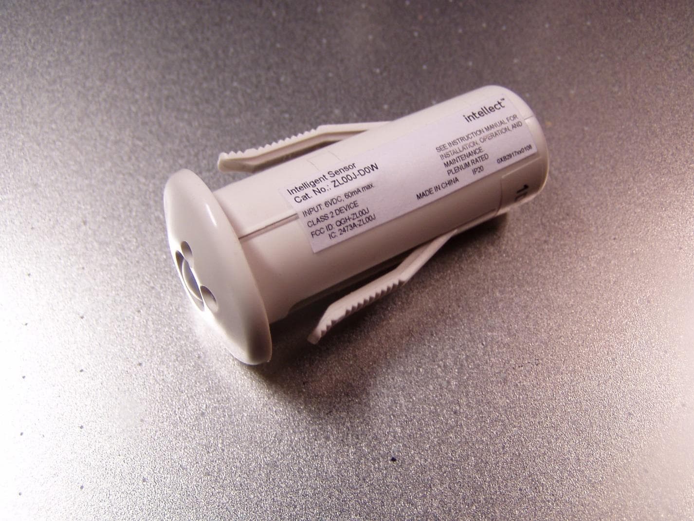
QGH-ZL00J
Apr 07, 2020ZL00J-D0W Intellect Sensor Head
Equipment Class
DTS - Digital Transmission System
QGH-ZBMG
Jan 02, 20200XB1803 Module
Equipment Class
DTS - Digital Transmission System