QGH-WSG15RADIO CONTROLLED OUTLET
Leviton Manufacturing Co., Inc.
Click to zoom
Application Details
- Equipment Class
- DSC - Part 15 Security/Remote Control Transmitter
- Date of Grant
- Apr 10, 2013
- Application Purpose
- Original Equipment
- Date of Application
- Apr 10, 2013
- Equipment Note
- RADIO CONTROLLED OUTLET
- Frequency Range
- 315.00000000 - 315.00000000
- Country
- United States
Documents & Files
Document Text
Text extracted from the exhibit documents filed with the FCC. Open a document above to read the original.
Users Manual
LevNet RF Receptacle (Tamper-Resistant) Cat. Nos. WSG15-0DZ (Top Controlled), WSG15-TDZ (Dual Controlled, Title 24) Ratings: 125VAC, 60Hz, 15A Switched: 15A General Use/Resistive, 1800W Incandescent, 1800VA Inductive, 1/2HP, 120VAC INSTALLATION AND QUICK START GUIDE WARNINGS AND CAUTIONS: • TO AVOID FIRE SHOCK OR DEATH; TURN OFF POWER at circuit breaker or fuse and test that power is off before wiring, servicing, installing or removing device. • To be installed and/or used in accordance with electrical codes and regulations. • If you are unsure about any part of these instructions, consult an electrician. • To ensure that there is adequate room for wires, Leviton recommends using 3-1/2 inch deep wall boxes, at a minimum. For single-gang applications, this would be an 18-cubic inch wall box, at a minimum. • Use this device with copper or copper clad wire only. DESCRIPTION The LevNet RF Receptacle (WSG15) is designed to use wireless communication and provide remote control of your lighting. The device will control lighting or equipment attached to the receptacle by receiving a wireless signal (315MHz) from other EnOcean enabled wireless devices. Devices can be learned directly into the unit via the Programming Mode Selection Menu or wireless via the Leviton ComWi software and WSCOM-03W. The WSG15 receptacle has a 50-100 ft. reception range depending upon the environment and transmission device. Range will be reduced by signals having to transmit through walls. NOTE: Some motorized devices, such as a power drill, can significantly reduce the effective range of the WSG15. Transmit range for WSG15, when utilized as a repeater or for initial setup/commissioning is between 20-50 ft. FEATURES • Able to switch single (WSG15-0DZ) or dual (WSG15-TDZ) outlets ON/OFF remotely • Scene Capable • ON/OFF LED • Can be remotely configured and commissioned using the LevNetRF ComWi software and EnOcean WSCOM hardware • Includes repeater function (Level 1 or 2) to increase wireless reception to other devices • Ease of installation – No new wiring • Built-In tamper resistant barrier designed to limit improper insertion of small objects into receptacle contact slots COMPATIBLE DEVICES Most EnOcean Alliance enabled devices which conform to the EnOcean Equipment Profile (EEP) are compatible with the WSG15 receptacle. This includes but is not limited to room controllers, occupancy sensors, key cards, unpowered switches, door and window sensors made by Leviton as well as other EnOcean Alliance companies which support EEP 2.1 and above. EQUIPMENT NEEDED FOR INSTALLATION • Slotted/Phillips Screwdriver • Pencil • Electrical Tape • Cutters • Pliers • Ruler INSTALLATION Changing the color of your receptacle: Your receptacle includes five color options. The receptacle ships with the white frame attached. To change color of the frame, proceed as follows: WARNING: TO AVOID FIRE SHOCK OR DEATH; TURN OFF POWER at circuit breaker or fuse and test that power is off before wiring! Step 1 INSTALLING YOUR RECEPTACLE NOTE: Use check boxes when Steps are completed. Connect wires per WIRING DIAGRAM as follows: • Green or bare copper wire in wall box to Green terminal screw. • Line Hot wall box wire to terminal screw (Black) marked "LINE". • Line Neutral wall box wire to terminal screw (Silver) marked "NEUTRAL". • Proceed to Step 4. INSTALLING SOFTWARE (OPTIONAL) For additional details refer to the ComWi Installation & Operation instructions. Consult the factory for details. DI-000-WSG15-02A-X5 Single Controlled Top OutletDual Controlled Outlets Push in side at tab to release Line up tabs and press in sides one at a time to attach ONOFF ONOFF ONOFF ONOFF ONOFF ONOFF ONOFFONOFF ONOFF ONOFF ONOFF ONOFF Wiring the receptacle: This receptacle can be wired using side wire terminal screws or through backwire openings. Choose appropriate wire stripping specifications accordingly. Step 3 Side Wire Connection Side wire terminals accept #14-12 AWG solid copper wire only. Back Wire Connection (either hole may be used) Back wire openings accept #14-12 AWG solid copper wire only. • Make sure that the ends of the wires from the wall box are straight (cut if necessary). • Remove insulation from each wire in the wall box as shown. 5/8" (1.6 cm) Strip Gage (measure bare wire here) Cut (if necessary) Identifying your wiring application (most common): NOTE: If the wiring in your wall box does not resemble this configuration, consult an electrician. Step 2 1 2 3 Single Pole 1. Line (Hot) 2. Neutral 3. Ground Step 4 Testing your Receptacle prior to mounting in wall box: • Position all wires to provide room in outlet wall box for device. • Partially screw in mounting screws in wall box mounting holes. NOTE: Dress wires with a bend as shown in diagram in order to relieve stress when mounting device. • Restore power at circuit breaker or fuse. • The green Locator light should turn ON. If locator light does not turn ON, refer to the TROUBLESHOOTING section. Neutral (Silver) Line (Black) Green Ground CONTROLLED Step 5 Receptacle Mounting: TURN OFF POWER AT CIRCUIT BREAKER OR FUSE. • Installation may now be completed by tightening mounting screws into wall box. Attach wallplate. • Restore power at circuit breaker or fuse. Installation is complete. CONTROLLED Programming Instructions: All devices are learned in a "reduced sensitivity" mode to avoid interference from other devices which may be active in areas close by. This reduction of sensitivity reduces the range so devices learned to the WSG15 receptacle should be within 10 ft when learning. Factory Defaults (only accessible via ComWi software): • Occupancy Sensor Timeout: 20 minutes • Momentary Egress Delay: 0 seconds • Repeater Mode: ON, Level 1 Time-Outs: When used with an occupancy sensor the WSG15 has six time-out settings: 2, 5, 10, 15, 20, or 30 min. (a longer timeout is recommended when using self powered devices in dark spaces). The values of time- out defaults to 20 minutes and can only be changed …
Text truncated - open the document above for the full version.
External Photos
Front View of the EUT Back View of the EUT Front View with EUT Removed from Metal Wallbox Back/Side View of the EUT Outside Metal Wallbox View of the Right Side of EUT
ID Label/Location Info
Page 1 of 2 Labels: WSG15-0DZ and WSG15-TDZ 22 March 2013 – v1.00 WSG15-0DZ Label (Industry Canada ID and FCC) Figure 1. WSG15-0DZ (Same for IC and FCC) WSG15-TDZ Label (Industry Canada ID and FCC) Figure 2. WSG15-TDZ (Same for IC and FCC) Label Dimension Figure 3. WSG15-0DZ and WSG15-TDZ
ID Label/Location Info
Page 2 of 2 Label Specifications PURCHASE AS SHOWN FROM IDENTIFICATION PRODUCTS INC. OR FROM AN ENGINEERING APPROVED VENDOR. MATERIAL: .002" THICK WHITE POLYESTER WITH V-156 PERMANENT ADHESIVE, .001" THICK CLEAR GLOSS POLYESTER OVERLAMINATION. PRINT BLACK CHARACTERS AND GRAPHICS PER ARTWORK ORA5118-Dxx. GRAPHICS SHOWN FOR ILLUSTRATION PURPOSES ONLY. Label Location The white label with black text will be printed and placed on the back of the WSG15-0DZ and WSG15-TDZ in the area shown. Alignment is such that LINE = BLACK SCREW, NEUTRAL = WHITE SCREW, GROUND = GREEN SCREW. or Figure 4. Label WSG15-0DZ or WSG15-TDZ Figure 5. Back of WSG15 Receptacle: Label affixes to textured surface. “LINE” is aligned with black screw.
Internal Photos
Front View of the Plastic Housing Components of the EUT Back View of the Plastic Housing Components of the EUT Front View Internal Plastic Housing with Antenna Installed Back View Internal Plastic Housing with Antenna Installed View of the Antenna View of the Back Side of the Power Supply/Control PCB View of the Front Side of the Power Supply/Control PCB View of the Front Side of the RF PCB View of the Back Side of the RF PCB View of the Circuitry Under the RF Shield
Test Report
Nemko-CCL, Inc. 1940 West Alexander Street Salt Lake City, UT 84119 801-972-6146 Test Report Certification Test Of: WSG15-0DZ and WSG15-TDZ FCC ID: QGH-WSG15 Test Specifications: FCC Part 15, Subpart C Test Report Serial No: 233247-3.2 Applicant: Leviton Manufacturing Co., Inc. 201 North Service Road Melville, NY 11747 Date of Test: March 19, 2013 Issue Date: March 20, 2013 Accredited Testing Laboratory By: NVLAP Lab Code 100272‐0 Nemko-CCL, Inc. TEST REPORT: 233247-3.2 REPORT ISSUE DATE: 03/20/2013 Page 2 of 43 TRF-15.231 Issue 1 April 2012 CERTIFICATION OF ENGINEERING REPORT This report has been prepared by Nemko-CCL, Inc. to document compliance of the device described below with the certification requirements of FCC Part 15, Subpart C. This report may be reproduced in full. Partial reproduction of this report may only be made with the written consent of the laboratory. The results in this report apply only to the sample tested. - Applicant: Leviton Manufacturing Co., Inc. - Manufacturer: Leviton Manufacturing Co., Inc. - Brand Name: Leviton - Model Number: WSG15-0DZ and WSG15-TDZ - FCC ID Number: QGH-WSG15 On this 20 th day of March 2013, I, individually and for Nemko-CCL, Inc., certify that the statements made in this engineering report are true, complete, and correct to the best of my knowledge, and are made in good faith. Although NVLAP has accredited the Nemko-CCL, Inc. EMC testing facilities, this report must not be used to claim product certification, approval, or endorsement by NVLAP, NIST, or any agency of the federal government. Nemko-CCL, Inc. Tested by: Norman P. Hansen Test Technician Reviewed by: Thomas C. Jackson General Manager Nemko-CCL, Inc. TEST REPORT: 233247-3.2 REPORT ISSUE DATE: 03/20/2013 Page 3 of 43 TRF-15.231 Issue 1 April 2012 TABLE OF CONTENTS PAGE SECTION 1.0 CLIENT INFORMATION .................................................................................4 SECTION 2.0 EQUIPMENT UNDER TEST (EUT)..................................................................5 SECTION 3.0 TEST SPECIFICATION, METHODS & PROCEDURES .............................7 SECTION 4.0 OPERATION OF EUT DURING TESTING..................................................11 SECTION 5.0 SUMMARY OF TEST RESULTS ...................................................................12 SECTION 6.0 MEASUREMENTS, EXAMINATIONS AND DERIVED RESULTS ..........13 APPENDIX 1 TEST PROCEDURES AND TEST EQUIPMENT .........................................20 APPENDIX 2 PHOTOGRAPHS ................................................................................................25 Nemko-CCL, Inc. TEST REPORT: 233247-3.2 REPORT ISSUE DATE: 03/20/2013 Page 4 of 43 TRF-15.231 Issue 1 April 2012 SECTION 1.0 CLIENT INFORMATION 1.1 Applicant: Company Name: Leviton Manufacturing Co., Inc. 201 North Service Road Melville, NY 11747 Contact Name: Frank Tse Title: Manager 1.2 Manufacturer: Company Name: Leviton Manufacturing Co., Inc. 20497 SW Teton Avenue Tualatin, OR 97062 Contact Name: Ken Vannice Title: Manager of Codes, Standards, and Compliance Nemko-CCL, Inc. TEST REPORT: 233247-3.2 REPORT ISSUE DATE: 03/20/2013 Page 5 of 43 TRF-15.231 Issue 1 April 2012 SECTION 2.0 EQUIPMENT UNDER TEST (EUT) 2.1 Identification of EUT: Brand Name: Leviton Model Number: WSG15-0DZ and WSG15-TDZ Serial Number: None 2.2 Description of EUT: The WSG15-0DZ and WSG15-TDZ are AC outlets that have a 315 MHz transceiver that controls the outlet. WSG15-0DZ and WSG15-TDZ are installed in metal wall boxes. The WSG15-0DZ controls one of the two AC outlets where the WSG15-TDZ controls both outlets. The only difference in the devices is whether 2 outlets are connected to the control circuitry or only one. The 315 MHz transceiver uses a 6 ¼” metal wire as an antenna, routed in a slot in the plastic front case of the device. This report covers the transmitter circuitry of the device subject to FCC Part 15, Subpart C. The circuitry of the device, subject to FCC Part 15, Subpart B is covered in Nemko-CCL, Inc. report 233247-2. 2.3 EUT and Support Equipment: Brand Name Model Number Serial No. FCC ID Number Description Name of Interface Ports / Interface Cables BN: Leviton MN: WSG15-0DZ (Note 1) SN: None QGH-WSG15 Wireless Controlled Outlet See Section 2.4 BN: Leviton MN: WSG15-TDZ (Note 1) SN: None QGH-WSG15 Wireless Controlled Outlet See Section 2.4 BN: Wavetek MN: Model 30 SN: 2269 None Device used as Load AC In/3 conductor cord (Note 2) Note: (1) EUT (2) Interface port connected to EUT (See Section 2.4) Nemko-CCL, Inc. TEST REPORT: 233247-3.2 REPORT ISSUE DATE: 03/20/2013 Page 6 of 43 TRF-15.231 Issue 1 April 2012 The support equipment listed above was not modified in order to achieve compliance with this standard. 2.4 Interface Ports on EUT: Name of Ports No. of Ports Fitted to EUT Cable Descriptions/Length AC In 1 3 conductor power cord/1 meter AC Out 1 3 conductor extension cord/>3 meters 2.5 Modification Incorporated/Special Accessories on EUT: There were no modifications or special accessories required to comply with the specification. Nemko-CCL, Inc. TEST REPORT: 233247-3.2 REPORT ISSUE DATE: 03/20/2013 Page 7 of 43 TRF-15.231 Issue 1 April 2012 SECTION 3.0 TEST SPECIFICATION, METHODS & PROCEDURES 3.1 Test Specification: Title: FCC PART 15, Subpart C (47 CFR 15) Section 15.203, Section 15.207, and Section 15.231 Periodic operation in the band 40.66-40.70 MHz and above 70 MHz. Purpose of Test: The tests were performed to demonstrate initial compliance. 3.2 Methods & Procedures: 3.2.1 §15.203 An intentional radiator shall be designed to ensure that no antenna other than that furnished by the responsible party shall be used with the device. The use of a permanently attached antenna or of an antenna that uses a unique coupling to the intentional radiator shall be considered sufficient to comply with the provisions of this Section. The manufacturer may design the unit so that a broken antenna can be replaced by the user, but the use of a standard antenn…
Text truncated - open the document above for the full version.
Test Setup Photos
Front View Radiated Disturbance Worst Case Configuration Back View Radiated Disturbance Worst Case Configuration Front View Conducted Disturbance Worst Case Configuration Back View Conducted Disturbance Worst Case Configuration
Contact Information
Applicant
Frank Tse(Manager)
Test Firm
VPI TechnologyJason Stewart
[email protected]801-495-2310
Technical Specifications
| # | Rule Parts | Frequency Range | Power Output |
|---|---|---|---|
| 1 | 15.231 | 315 MHz - 315 MHz | - |
Other Applications from Leviton Manufacturing Co., Inc.

QGH-B167601
Jun 25, 2020Lumina Wall Dimmer and Wireless Load Control Dimmer
Equipment Class
DTS - Digital Transmission System
QGH-B167602
Jun 25, 2020Lumina RF Wall Switch and Wireless Load Controller
Equipment Class
DTS - Digital Transmission System
QGH-PVDIM
Apr 07, 2020O5C04-IDW, O5C20-MDW, 06C04-IDW, 06C20-MDW, V6C04-IDW, V6C20-MDW
Equipment Class
DTS - Digital Transmission System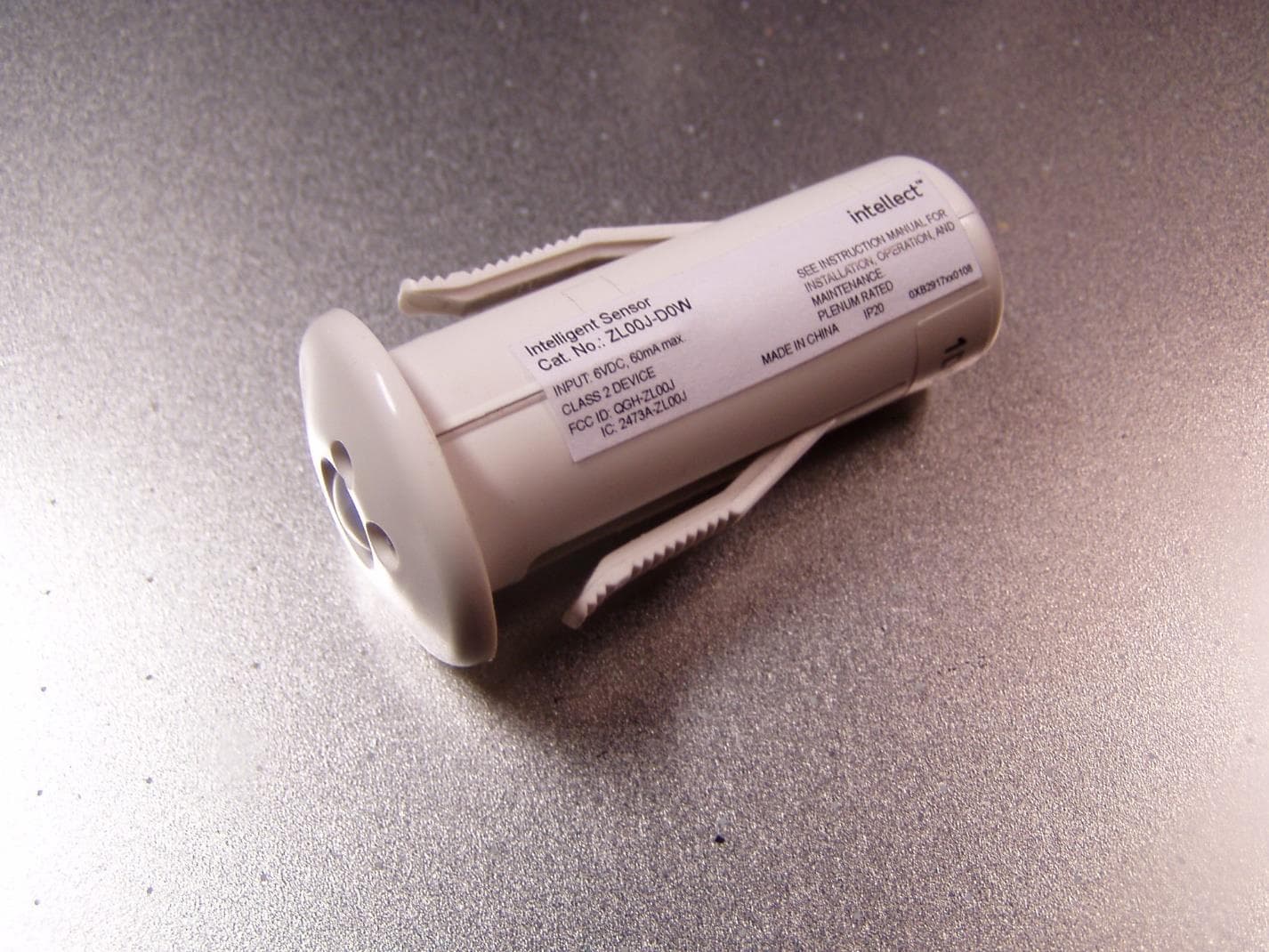
QGH-ZL00J
Apr 07, 2020ZL00J-D0W Intellect Sensor Head
Equipment Class
DTS - Digital Transmission System
QGH-ZBMG
Jan 02, 20200XB1803 Module
Equipment Class
DTS - Digital Transmission System