QGZB2000Vocera 802.11 badge
Vocera Communications
Click to zoom
Application Details
- Equipment Class
- DTS - Digital Transmission System
- Date of Grant
- Sep 09, 2007
- Application Purpose
- Original Equipment
- Date of Application
- Sep 07, 2007
- Equipment Note
- Vocera 802.11 badge
- Frequency Range
- 2412.00000000 - 2462.00000000
- Company
- Vocera Communications
- Country
- United States
Documents & Files
Document Text
Text extracted from the exhibit documents filed with the FCC. Open a document above to read the original.
Users Manual
Vocera User Guide Version 2.0 ii ··· Copyrights and Trademarks Copyright © 2002-2003 Vocera Communications, Inc. All rights reserved. Vocera® is a registered trademark of Vocera Communications, Inc. This product includes software whose copyright is owned by MySQL AB. MySQL ™ is a trademark of MySQL AB in the USA. This product includes software developed by the Apache Software Foundation (http://www.apache.org). ACELP® and VoiceAge are either registered trademark or trademark of VoiceAge Corporation in the United States and/or other countries and used under license from VoiceAge Corporation. The ACELP® (*) codec in this product is used under license from VoiceAge Corporation. Copy- right © 2002-2003 Voice Age Corporation. All rights reserved. Java and all Java-based marks are trademarks or registered trademarks of Sun Microsystems, Inc. in the United States and other countries. Nuance, Nuance Verifier, Nuance Vocalizer, and Nuance Voice Platform are trademarks or registered trademarks of Nuance Communications, Inc. Microsoft® Windows®, Windows 2000®, Windows XP®, and Microsoft® Internet Explorer are registered trademarks of Microsoft Corporation in the United States and/or other countries. All other trademarks, service marks, registered trademarks, or registered service marks are the property of their respective owner/s. All other brands and/or product names are the trademarks (or registered trade- marks) and property of their respective owner/s. Vocera Communications, Inc. www.vocera.com tel :: +1 408 790 4100 fax :: +1 408 790 4101 Part No. :: 930-00529 rev E, 7-October-2003 What’s New ··· iii What’s New Vocera 2.0 provides numerous improvements over the previous version of Vocera. This chapter summarizes the changes to the voice commands you can use with badges. Vocera 2.0 provides the following new features and enhancements for voice commands: • Urgent calls, broadcasts, and conferencing commands let you break through to all recipients, regardless of what they are doing at the time. See Issuing Urgent Commands on page 47. • Commands to let group managers add users to a group, remove users from a group, and record name prompts for groups. In version 2.0, only group managers and system administrators can record name prompts for a group. See Commands for Group Managers on page 53. • New voice commands let you control whether the badge automati- cally answers incoming calls or whether it asks if you can take a call before connecting it. See Using the Auto Answer Commands on page 37. • Commands to call people or places your system administrator sets up as address book entries. You can also use other related voice commands with address book entries. See Calling an Address Book Entry or Buddy on page 40. iv ··· Vocera User Guide Important Safety Instructions ··· v Important Safety Instructions The Vocera badge (including its battery component) and the Vocera battery charger are electronic devices. Care appropriate to the use of any electronic device should be taken in using the badge and the battery charger in order to avoid possible injury (such as from shock) and damage (such as from fire). In addition, the Vocera badge is a wireless communication device and works by generating radio frequency (RF) signals. These sig- nals, although generally lower in strength than a typical cell phone, can interfere with other electronic devices that are not appropriately shielded against RF. If the Vocera badge will be used in proximity to sensitive electronic devices for which inter- ference could result in serious consequences (for example, a heart pacemaker), you must consult with the manufacturer of that device in order to determine the operating safety of the Vocera badge. In order to foster comfortable use of the badge and avoid damage to hearing, do not bring the speaker within close proximity of the ear while the badge is powered on. References below to the “badge” refer to the Vocera badge, including its battery component. References to the “product” refer to the badge and the Vocera battery charger. In addition to other basic safety precautions appropriate to the use of electronic, wireless devices, please follow the safety and use instructions below. Badge and Battery Charger Safety 1.Read, understand, and follow all warnings and instructions in the product documentation and on the product itself. 2.To reduce the risk of electric shock, do not disassemble any part of the product. Take the badge or charger to qualified service person- nel when service or repair work is required. Opening or removing covers may expose you to dangerous voltages or other risks. Incor- rect reassembly can cause electric shock when you use the product again. vi ··· Vocera User Guide 3.Do not put anything other than a Vocera badge or Vocera battery into a charger slot, as other objects may touch dangerous voltage points or short out parts, which could result in fire or electric shock. 4.Do not place the product on an unstable surface, as a fall may cause serious damage to the product. 5.Never place the badge or charger near or over a radiator or heat register. Do not operate the charger in a cabinet or other enclosure unless proper ventilation is provided. 6.Do not position the badge or battery charger near water; for exam- ple, near a sink, wash bowl, or toilet. Do not spill liquid of any kind on the product. Doing so may short out parts, causing damage to the product and creating the risk of fire or electric shock. 7.Take the badge or charger to a qualified service provider in these circumstances: • If liquid has been spilled into the badge or charger, or if rain or water have touched the badge or charger. • If the badge or charger does not operate normally after you fol- low the operating instructions. • If the badge or charger has been dropped or damaged. • If the badge or charger exhibits a distinct degradation in perfor- mance. • If the power cord or plug on the charger is damaged or frayed. 8.Unplug the charger…
Text truncated - open the document above for the full version.
Cover Letter(s)
To: Federal Communications Commission 7435 Oakland Mills Road Columbia, Maryland 21046 Subject: Confidentiality Request for Part 15 Certification Application Gentlemen, On behalf of Vocedra Communications I request that the following documents: • Any/All circuit schematics. • Any/All electrical block diagrams • Operational Descriptions Associated with the following Part 15 Certification applications (FCC ID): QGZxXXXX be withheld from public disclosure per Section 0.459 of the FCC Rules. This request is made under the provisions of Section 0.457(d) of the FCC rules and Sections 552(b)(4) of the Freedom of information Act. These Sections authorize withholding from public inspection, materials which would be privileged as a matter of law if retained by the person submitting them in addition to materials, which would not customarily be released to the public, by that person. If you have any questions, please do not hesitate to contact me at: [email protected] or (408) 832-7053 Sincerely, David Waitt Consultant representing Vocera 20600 Lazaneo Drive 3rd Floor Cupertino, CA 95014 www.vocera.com
Cover Letter(s)
American Telecommunications Certification Body Inc. 6731 Whittier Ave, McLean, VA 22101 August 20, 2007 RE: FCC ID: QGZB2000_ATCB005302 Attention: Dave Waitt I have a few comments on this Application. Please note that further comments may arise in response to answers provided to the questions below. 1. Please note that the operational description states that a “Bluetooth coexistence interface is also supported.” Please advise if this device contains a BT transmitter or if it is a DTS only application. 2. Please note that the operational description states that the device operates in the 5GHz bands (see section 2.3 of the operational description). Please explain if this device does operate in the 5GHz bands. If it does, please provide appropriate data and correct the appropriate documentation. If the operational description is a generic description for a family of devices, please clearly indicate in the document which specific sections do and do not apply to this device. 3. Please note that the device has a clip called the “universal clip”. This clip appears to easily allow the device to be worn on the body. Please also note that the output power of the device is over 300mW. Please also note that the manual clearly indicates that an external headset containing a speaker and microphone can be used with the device, also clearly indicating possibility of use on the body. Please also note that the manual states SAR testing has been performed. Please explain why Body SAR testing was not performed/provided on/for this device. If no reasonable justifiable explanation can be provided, please provide the Body SAR report. Dennis Ward mailto:[email protected] The items indicated above must be submitted before processing can continue on the above referenced application. Failure to provide the requested information may result in application termination. Correspondence should be considered part of the permanent submission and may be viewed from the Internet after a Grant of Equipment Authorization is issued. Please do not respond to this correspondence using the email reply button. In order for your response to be processed expeditiously, you must submit your documents through the AmericanTCB.com website. Also, please note that partial responses increase processing time and should not be submitted. Any questions about the content of this correspondence should be directed to the sender.
Cover Letter(s)
To: ATCB From: Vocera Communications RE: FCC ID: QGZB2000_ATCB005302 Reply to TCB comments / Questions 1. Please note that the operational description states that a “Bluetooth coexistence interface is also supported.” Please advise if this device contains a BT transmitter or if it is a DTS only application. VOCERA: The badge DOES NOT support Bluetooth. It was anticipated in the early stages of development, but that functionality was removed from this version of the device 2. Please note that the operational description states that the device operates in the 5GHz bands (see section 2.3 of the operational description). Please explain if this device does operate in the 5GHz bands. If it does, please provide appropriate data and correct the appropriate documentation. If the operational description is a generic description for a family of devices, please clearly indicate in the document which specific sections do and do not apply to this device. VOCERA: The device DOES NOT include 5 GHz operation. The Op Desc provided describes the full capabilities of the chipset. The chipset supports other function that would also require supporting circuitry external to the chip and is not incorporated into the Vocera badge. Any reference to 802.11 A , or Bluetooth are not applicable to the Vocera Communications badge. 3. Please note that the device has a clip called the “universal clip”. This clip appears to easily allow the device to be worn on the body. Please also note that the output power of the device is over 300mW. Please also note that the manual clearly indicates that an external headset containing a speaker and microphone can be used with the device, also clearly indicating possibility of use on the body. Please also note that the manual states SAR testing has been performed. Please explain why Body SAR testing was not performed/provided on/for this device. If no reasonable justifiable explanation can be provided, please provide the Body SAR report. VOCERA: Body SAR has been tested and the SAR report uploaded to ATCB. Please do not hesitate to contact me if there are any additional concerns. On Behalf of Vocera Communications, Best Regards, David Waitt
ID Label/Location Info
300-01734_A 12345YMXXX 12345YMXXX PTC xxx / xx / xxxPTC xxx / xx / xxx This Vocera B2000 Communications Badge may be connected to the Telecom Network This Vocera B2000 Communications Badge may be connected to the Telecom Network TELEPERMITTELEPERMIT Die L ine - R efer to pa rt dra wing 300-01734_A for exa ct mecha nica l dimens ions of die line. C ompos ite B a dge L a bel: P rinted on light s ilver colored polyes ter la bel s tock, s hown here a s P MS 877C . S ilver coloring mus t be non-meta llic B a dge L a bel: B la ck/G reen L a yer 300-01734_A a rt V ocera , Inc. 07. 19. 07 C . Whea ton N ote: a ll holes in die line view a re thru holes . P unch through la bel a nd ba cking s tock to remove ma teria l. 55.4mm (ref) 34mm (ref) P rotected by U . S . pa tents lis ted on www. vocera . com Ma de in U . S . A. Model: B 2000 F C C ID: Q G ZB 2000 IC : 4362A-B 2000 1588 N 79 Z115 C US ®
RF Exposure Info
Company: Vocera Communications FCC ID: QGZB2000 IC ID: 4362A-B2000 Model(s): B2000 DUT Type: Portable Body-worn Communications Badge with 802.11b/g WLAN 2007 Celltech Labs Inc. This document is not to be reproduced in whole or in part without the prior written permission of Celltech Labs Inc.Page 46 of 47 Date(s) of Evaluation June 25 & July 17, 2007 Test Report Serial No. 061807QGZ-T838-S15W Test Report Revision No. Revision 1.0 Test Report Issue Date August 20, 2007 Description of Test(s) Specific Absorption Rate RF Exposure Category General Population Certificate No. 2470.01 APPENDIX F - PROBE CALIBRATION
RF Exposure Info
Company: Vocera Communications, Inc. FCC ID: QGZB2000 IC ID: 4362A-B2000 Model(s): B2000 DUT Type: Portable Communications Badge with 802.11b/g WLAN (held-to-ear) 2007 Celltech Labs Inc. This document is not to be reproduced in whole or in part without the prior written permission of Celltech Labs Inc.Page 47 of 48 Date(s) of Evaluation July 17 & August 31, 2007 Test Report Serial No. 061807QGZ-T838-S15W H Test Report Revision No. Revision 1.0 Test Report Issue Date September 06, 2007 Description of Test(s) Specific Absorption Rate RF Exposure Category General Population Certificate No. 2470.01 APPENDIX F - PROBE CALIBRATION
RF Exposure Info
Company: Vocera Communications FCC ID: QGZB2000 IC ID: 4362A-B2000 Model(s): B2000 DUT Type: Portable Body-worn Communications Badge with 802.11b/g WLAN 2007 Celltech Labs Inc. This document is not to be reproduced in whole or in part without the prior written permission of Celltech Labs Inc.Page 45 of 47 Date(s) of Evaluation June 25 & July 17, 2007 Test Report Serial No. 061807QGZ-T838-S15W Test Report Revision No. Revision 1.0 Test Report Issue Date August 20, 2007 Description of Test(s) Specific Absorption Rate RF Exposure Category General Population Certificate No. 2470.01 APPENDIX E - SYSTEM VALIDATION Celltech Labs Inc. 21-364 Lougheed Rd., Kelowna, B.C. V1X 7R8 Canada Tel. 250-765-7650 x Fax. 250-765-7645 x e-mail: [email protected] www.celltechlabs.com 2007 Celltech Labs Inc. This document is not to be reproduced in whole or in part without the prior written permission of Celltech Labs Inc. Page 1 of 12 Date of Evaluation: June 08, 2007 Document Serial No.: SV2450B-060807-R1.2 Evaluation Type: System Validation Validation Dipole: 2450 MHz Fluid Type: Brain 2450 MHz SYSTEM VALIDATION Type: Asset Number: Serial Number: Place of Validation: Date of Validation: Celltech Labs Inc. certifies that the 2450 MHz System Validation was performed on the date indicated above. Performed by: Approved by: 2450 MHz Validation Dipole 150 Celltech Labs Inc. June 08, 2007 00025 Cheri Frangiadakis Jon Hughes 2007 Celltech Labs Inc. This document is not to be reproduced in whole or in part without the prior written permission of Celltech Labs Inc. Page 2 of 12 Date of Evaluation: June 08, 2007 Document Serial No.: SV2450B-060807-R1.2 Evaluation Type: System Validation Validation Dipole: 2450 MHz Fluid Type: Brain 1. Dipole Construction & Electrical Characteristics The validation dipole was constructed in accordance with the requirements specified in IEEE Standard 1528- 2003 and International Standard IEC 62209-1:2005. The electrical properties were measured using an HP 8753ET Network Analyzer. The network analyzer was calibrated to the validation dipole N-type connector feed point using an HP85032E Type N calibration kit. The dipole was placed parallel to a planar phantom at a separation distance of 10.0mm from the simulating fluid using a loss-less dielectric spacer. The measured input impedance is: Feed point impedance at 2450 MHz Re{Z} = 45.100: Im{Z} = 3.5605: Return Loss at 2450 MHz -23.411dB Reference dipole - basic mechanical parameters 2007 Celltech Labs Inc. This document is not to be reproduced in whole or in part without the prior written permission of Celltech Labs Inc. Page 3 of 12 Date of Evaluation: June 08, 2007 Document Serial No.: SV2450B-060807-R1.2 Evaluation Type: System Validation Validation Dipole: 2450 MHz Fluid Type: Brain 2. Validation Dipole VSWR Data 2007 Celltech Labs Inc. This document is not to be reproduced in whole or in part without the prior written permission of Celltech Labs Inc. Page 4 of 12 Date of Evaluation: June 08, 2007 Document Serial No.: SV2450B-060807-R1.2 Evaluation Type: System Validation Validation Dipole: 2450 MHz Fluid Type: Brain 3. Validation Dipole Dimensions Frequency (MHz) L (mm) H (mm) D (mm) 300 396.0 250.0 6.0 450 270.0 167.0 6.0 835 161.0 89.8 3.6 900 149.0 83.3 3.6 1450 89.1 51.7 3.6 1800 72.0 41.7 3.6 1900 68.0 39.5 3.6 2000 64.5 37.5 3.6 2450 51.5 30.4 3.6 3000 41.5 25.0 3.6 4. Validation Phantom The validation phantom is the SAM (Specific Anthropomorphic Mannequin) phantom manufactured by Schmid & Partner Engineering AG. The SAM phantom is a Fiberglass shell integrated in a wooden table. The shape of the shell corresponds to the phantom defined by SCC34-SC2. It enables the dosimetric evaluation of left and right hand phone usage as well as body mounted usage at the flat phantom region. A cover prevents evaporation of the liquid. Reference markings on the phantom allow the complete setup of all predefined phantom positions and measurement grids by manually teaching three points in the robot. Shell Thickness: 2.0 ± 0.1 mm Filling Volume: Approx. 25 liters Dimensions: 50 cm (W) x 100 cm (L) SAM Phantom Fluid Depth (t 15.0 cm) 2007 Celltech Labs Inc. This document is not to be reproduced in whole or in part without the prior written permission of Celltech Labs Inc. Page 5 of 12 Date of Evaluation: June 08, 2007 Document Serial No.: SV2450B-060807-R1.2 Evaluation Type: System Validation Validation Dipole: 2450 MHz Fluid Type: Brain 5. 2450 MHz System Validation Setup 2007 Celltech Labs Inc. This document is not to be reproduced in whole or in part without the prior written permission of Celltech Labs Inc. Page 6 of 12 Date of Evaluation: June 08, 2007 Document Serial No.: SV2450B-060807-R1.2 Evaluation Type: System Validation Validation Dipole: 2450 MHz Fluid Type: Brain 6. 2450 MHz Dipole Setup 2007 Celltech Labs Inc. This document is not to be reproduced in whole or in part without the prior written permission of Celltech Labs Inc. Page 7 of 12 Date of Evaluation: June 08, 2007 Document Serial No.: SV2450B-060807-R1.2 Evaluation Type: System Validation Validation Dipole: 2450 MHz Fluid Type: Brain 7. SAR Measurement Measurements were made at the planar section of the SAM phantom using a dosimetric E-field probe EX3DV4 (S/N: 3600, conversion factor 6.37). The SAR measurement was performed with the E-field probe in mechanical detection mode only. The setup and determination of the forward power into the dipole was performed using the procedures described below. First the power meter PM1 (including attenuator Att1) is connected to the cable to measure the forward power at the location of the dipole connector (X). The signal generator is adjusted for the desired forward power at the dipole connector (taking into account the attenuation of Att1) as read by power meter PM2. After connecting the cable to the dipole, the signal generator is readjusted for the same reading at power meter PM2. If the signal generator does not allow adjustment in…
Text truncated - open the document above for the full version.
RF Exposure Info
Company: Vocera Communications, Inc. FCC ID: QGZB2000 IC ID: 4362A-B2000 Model(s): B2000 DUT Type: Portable Communications Badge with 802.11b/g WLAN (held-to-ear) 2007 Celltech Labs Inc. This document is not to be reproduced in whole or in part without the prior written permission of Celltech Labs Inc.Page 46 of 48 Date(s) of Evaluation July 17 & August 31, 2007 Test Report Serial No. 061807QGZ-T838-S15W H Test Report Revision No. Revision 1.0 Test Report Issue Date September 06, 2007 Description of Test(s) Specific Absorption Rate RF Exposure Category General Population Certificate No. 2470.01 APPENDIX E - SYSTEM VALIDATION Celltech Labs Inc. 21-364 Lougheed Rd., Kelowna, B.C. V1X 7R8 Canada Tel. 250-765-7650 x Fax. 250-765-7645 x e-mail: [email protected] www.celltechlabs.com 2007 Celltech Labs Inc. This document is not to be reproduced in whole or in part without the prior written permission of Celltech Labs Inc. Page 1 of 11 Date of Evaluation: June 08, 2007 Document Serial No.: SV2450M-060807-R1.3 Evaluation Type: System Validation Validation Dipole: 2450 MHz Fluid Type: Body 2450 MHz SYSTEM VALIDATION Type: Asset Number: Serial Number: Place of Validation: Date of Validation: Celltech Labs Inc. certifies that the 2450 MHz System Validation was performed on the date indicated above. Performed by: Approved by: 2450 MHz Validation Dipole 150 Celltech Labs Inc. June 08, 2007 00025 Cheri Frangiadakis Jon Hughes 2007 Celltech Labs Inc. This document is not to be reproduced in whole or in part without the prior written permission of Celltech Labs Inc. Page 2 of 11 Date of Evaluation: June 08, 2007 Document Serial No.: SV2450M-060807-R1.3 Evaluation Type: System Validation Validation Dipole: 2450 MHz Fluid Type: Body 1. Dipole Construction & Electrical Characteristics The validation dipole was constructed in accordance with the requirements specified in IEEE Standard 1528- 2003 and International Standard IEC 62209-1:2005. The electrical properties were measured using an HP 8753ET Network Analyzer. The network analyzer was calibrated to the validation dipole N-type connector feed point using an HP85032E Type N calibration kit. The dipole was placed parallel to a planar phantom at a separation distance of 10.0mm from the simulating fluid using a loss-less dielectric spacer. The measured input impedance is: Feed point impedance at 2450 MHz Re{Z} = 45.100: Im{Z} = 3.5605: Return Loss at 2450 MHz -23.411dB Reference dipole - basic mechanical parameters 2007 Celltech Labs Inc. This document is not to be reproduced in whole or in part without the prior written permission of Celltech Labs Inc. Page 3 of 11 Date of Evaluation: June 08, 2007 Document Serial No.: SV2450M-060807-R1.3 Evaluation Type: System Validation Validation Dipole: 2450 MHz Fluid Type: Body 2. Validation Dipole VSWR Data 2007 Celltech Labs Inc. This document is not to be reproduced in whole or in part without the prior written permission of Celltech Labs Inc. Page 4 of 11 Date of Evaluation: June 08, 2007 Document Serial No.: SV2450M-060807-R1.3 Evaluation Type: System Validation Validation Dipole: 2450 MHz Fluid Type: Body 3. Validation Dipole Dimensions Frequency (MHz) L (mm) H (mm) D (mm) 300 396.0 250.0 6.0 450 270.0 167.0 6.0 835 161.0 89.8 3.6 900 149.0 83.3 3.6 1450 89.1 51.7 3.6 1800 72.0 41.7 3.6 1900 68.0 39.5 3.6 2000 64.5 37.5 3.6 2450 51.5 30.4 3.6 3000 41.5 25.0 3.6 4. Validation Phantom The validation phantom is the SAM (Specific Anthropomorphic Mannequin) phantom manufactured by Schmid & Partner Engineering AG. The SAM phantom is a Fiberglass shell integrated in a wooden table. The shape of the shell corresponds to the phantom defined by SCC34-SC2. It enables the dosimetric evaluation of left and right hand phone usage as well as body mounted usage at the flat phantom region. A cover prevents evaporation of the liquid. Reference markings on the phantom allow the complete setup of all predefined phantom positions and measurement grids by manually teaching three points in the robot. Shell Thickness: 2.0 ± 0.1 mm Filling Volume: Approx. 25 liters Dimensions: 50 cm (W) x 100 cm (L) SAM Phantom Fluid Depth (t 15.0 cm) 2007 Celltech Labs Inc. This document is not to be reproduced in whole or in part without the prior written permission of Celltech Labs Inc. Page 5 of 11 Date of Evaluation: June 08, 2007 Document Serial No.: SV2450M-060807-R1.3 Evaluation Type: System Validation Validation Dipole: 2450 MHz Fluid Type: Body 5. 2450 MHz System Validation Setup 2007 Celltech Labs Inc. This document is not to be reproduced in whole or in part without the prior written permission of Celltech Labs Inc. Page 6 of 11 Date of Evaluation: June 08, 2007 Document Serial No.: SV2450M-060807-R1.3 Evaluation Type: System Validation Validation Dipole: 2450 MHz Fluid Type: Body 6. 2450 MHz Validation Dipole Setup 2007 Celltech Labs Inc. This document is not to be reproduced in whole or in part without the prior written permission of Celltech Labs Inc. Page 7 of 11 Date of Evaluation: June 08, 2007 Document Serial No.: SV2450M-060807-R1.3 Evaluation Type: System Validation Validation Dipole: 2450 MHz Fluid Type: Body 7. SAR Measurement Measurements were made at the planar section of the SAM phantom using a dosimetric E-field probe EX3DV4 (S/N: 3600, conversion factor 6.31). The SAR measurement was performed with the E-field probe in mechanical detection mode only. The setup and determination of the forward power into the dipole was performed using the procedures described below. First the power meter PM1 (including attenuator Att1) is connected to the cable to measure the forward power at the location of the dipole connector (X). The signal generator is adjusted for the desired forward power at the dipole connector (taking into account the attenuation of Att1) as read by power meter PM2. After connecting the cable to the dipole, the signal generator is readjusted for the same reading at power meter PM2. If the signal generator does no…
Text truncated - open the document above for the full version.
RF Exposure Info
Company: Vocera Communications, Inc. FCC ID: QGZB2000 IC ID: 4362A-B2000 Model(s): B2000 DUT Type: Portable Communications Badge with 802.11b/g WLAN (held-to-ear) 2007 Celltech Labs Inc. This document is not to be reproduced in whole or in part without the prior written permission of Celltech Labs Inc.Page 38 of 48 Date(s) of Evaluation July 17 & August 31, 2007 Test Report Serial No. 061807QGZ-T838-S15W H Test Report Revision No. Revision 1.0 Test Report Issue Date September 06, 2007 Description of Test(s) Specific Absorption Rate RF Exposure Category General Population Certificate No. 2470.01 APPENDIX D - SAR TEST SETUP & DUT PHOTOGRAPHS Company: Vocera Communications, Inc. FCC ID: QGZB2000 IC ID: 4362A-B2000 Model(s): B2000 DUT Type: Portable Communications Badge with 802.11b/g WLAN (held-to-ear) 2007 Celltech Labs Inc. This document is not to be reproduced in whole or in part without the prior written permission of Celltech Labs Inc.Page 39 of 48 Date(s) of Evaluation July 17 & August 31, 2007 Test Report Serial No. 061807QGZ-T838-S15W H Test Report Revision No. Revision 1.0 Test Report Issue Date September 06, 2007 Description of Test(s) Specific Absorption Rate RF Exposure Category General Population Certificate No. 2470.01 HEAD SAR TEST SETUP PHOTOGRAPHS Right Head Section / Cheek-Touch Position Company: Vocera Communications, Inc. FCC ID: QGZB2000 IC ID: 4362A-B2000 Model(s): B2000 DUT Type: Portable Communications Badge with 802.11b/g WLAN (held-to-ear) 2007 Celltech Labs Inc. This document is not to be reproduced in whole or in part without the prior written permission of Celltech Labs Inc.Page 40 of 48 Date(s) of Evaluation July 17 & August 31, 2007 Test Report Serial No. 061807QGZ-T838-S15W H Test Report Revision No. Revision 1.0 Test Report Issue Date September 06, 2007 Description of Test(s) Specific Absorption Rate RF Exposure Category General Population Certificate No. 2470.01 HEAD SAR TEST SETUP PHOTOGRAPHS Right Head Section / Ear-Tilt Position (15q) Company: Vocera Communications, Inc. FCC ID: QGZB2000 IC ID: 4362A-B2000 Model(s): B2000 DUT Type: Portable Communications Badge with 802.11b/g WLAN (held-to-ear) 2007 Celltech Labs Inc. This document is not to be reproduced in whole or in part without the prior written permission of Celltech Labs Inc.Page 41 of 48 Date(s) of Evaluation July 17 & August 31, 2007 Test Report Serial No. 061807QGZ-T838-S15W H Test Report Revision No. Revision 1.0 Test Report Issue Date September 06, 2007 Description of Test(s) Specific Absorption Rate RF Exposure Category General Population Certificate No. 2470.01 HEAD SAR TEST SETUP PHOTOGRAPHS Left Head Section / Cheek-Touch Position Company: Vocera Communications, Inc. FCC ID: QGZB2000 IC ID: 4362A-B2000 Model(s): B2000 DUT Type: Portable Communications Badge with 802.11b/g WLAN (held-to-ear) 2007 Celltech Labs Inc. This document is not to be reproduced in whole or in part without the prior written permission of Celltech Labs Inc.Page 42 of 48 Date(s) of Evaluation July 17 & August 31, 2007 Test Report Serial No. 061807QGZ-T838-S15W H Test Report Revision No. Revision 1.0 Test Report Issue Date September 06, 2007 Description of Test(s) Specific Absorption Rate RF Exposure Category General Population Certificate No. 2470.01 HEAD SAR TEST SETUP PHOTOGRAPHS Left Head Section / Ear-Tilt Position (15q) Company: Vocera Communications, Inc. FCC ID: QGZB2000 IC ID: 4362A-B2000 Model(s): B2000 DUT Type: Portable Communications Badge with 802.11b/g WLAN (held-to-ear) 2007 Celltech Labs Inc. This document is not to be reproduced in whole or in part without the prior written permission of Celltech Labs Inc.Page 43 of 48 Date(s) of Evaluation July 17 & August 31, 2007 Test Report Serial No. 061807QGZ-T838-S15W H Test Report Revision No. Revision 1.0 Test Report Issue Date September 06, 2007 Description of Test(s) Specific Absorption Rate RF Exposure Category General Population Certificate No. 2470.01 Front Side of DUTBack Side of DUT Top end of DUT Bottom end of DUT DUT PHOTOGRAPHS Company: Vocera Communications, Inc. FCC ID: QGZB2000 IC ID: 4362A-B2000 Model(s): B2000 DUT Type: Portable Com…
Text truncated - open the document above for the full version.
Contact Information
Applicant
Mike Morganstern(Head Of Operations)
Test Firm
Element Materials Technology Fremont NewarkDavid Bare
Technical Specifications
| # | Rule Parts | Frequency Range | Power Output |
|---|---|---|---|
| 1 | 15C | 2.41 GHz - 2.46 GHz | 316.00 mW |
Other Applications from Vocera Communications

QGZB3000N
Oct 20, 2014B3000N Communication Badge
Equipment Class
DTS - Digital Transmission System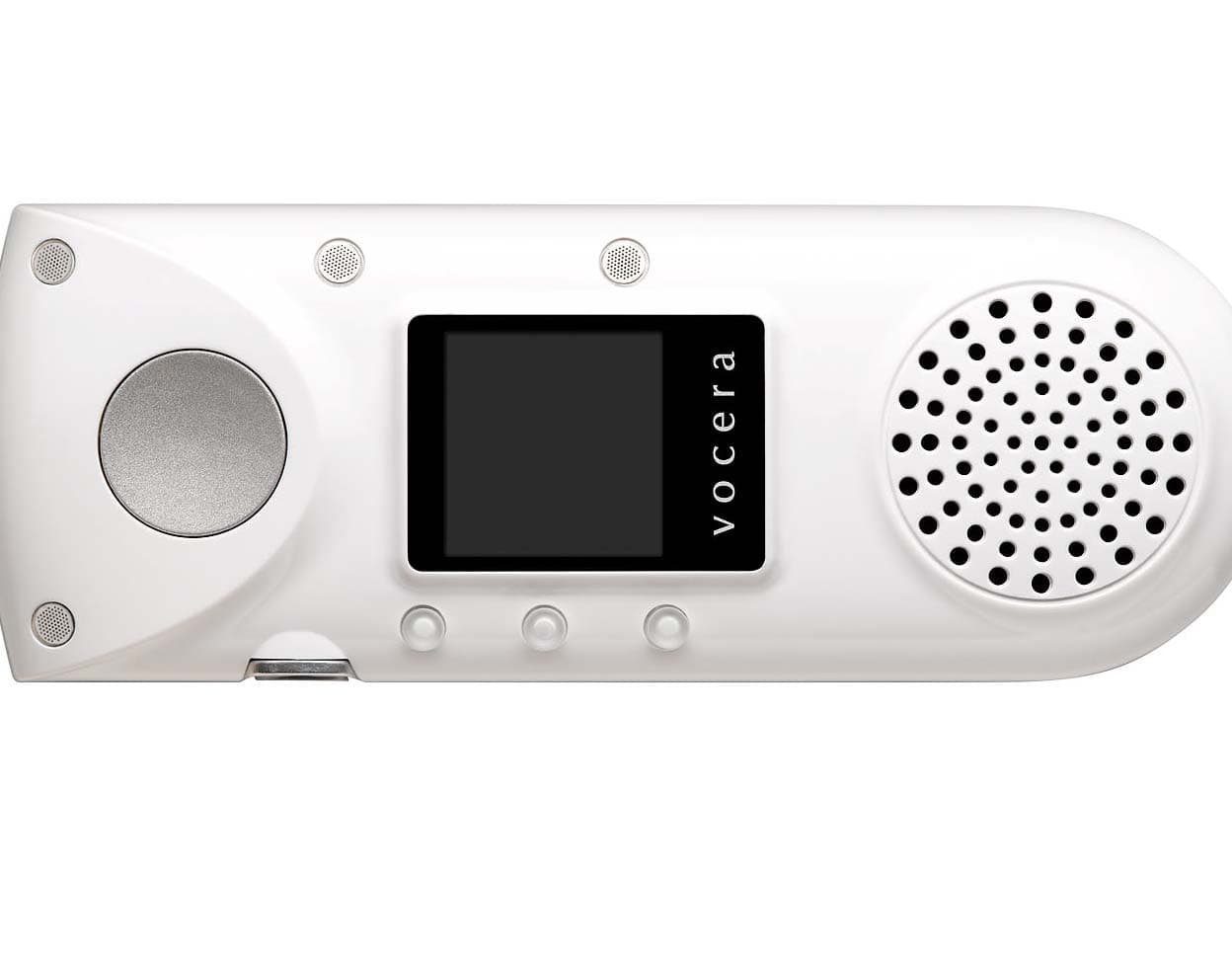
QGZAB3000
Nov 08, 2012Hands-free VOIP Communication Device
Equipment Class
DTS - Digital Transmission System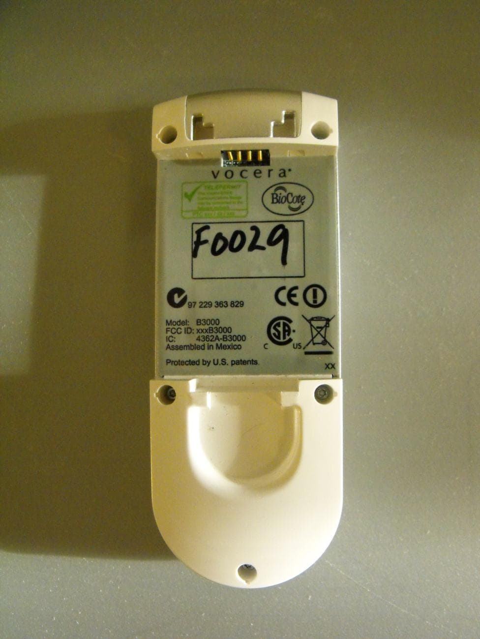
QGZB3000
Sep 29, 2011The Vocera B3000 is a hands-free VOIP Communication Device using 802.11b/g and bluetooth
Equipment Class
DSS - Part 15 Spread Spectrum Transmitter
QGZ-B1000
Nov 18, 2002Vocera B1000 Badge
Equipment Class
DTS - Digital Transmission System