QIE067X-0XTwo Wire Dimmer Module
Advanced Control Technologies, Inc.
Click to zoom
Application Details
- Equipment Class
- DXT - Part 15 Low Power Transceiver, Rx Verified
- Date of Grant
- Oct 10, 2004
- Application Purpose
- Original Equipment
- Date of Application
- Oct 10, 2004
- Equipment Note
- Two Wire Dimmer Module
- Frequency Range
- 908.40000000 - 908.40000000
- Country
- United States
Documents & Files
Document Text
Text extracted from the exhibit documents filed with the FCC. Open a document above to read the original.
Users Manual
ZDW120 Instructions P/D 100504 HomePro by ADVANCED CONTROL TECHNOLOGIES, INC. 0671-01 1 Radio Frequency Controlled, 600W, 120 VAC, Two Wire Wall Mounted Dimmer Switch ZDW120 ZDW120 WALL MOUNTED DIMMER The ZDW120 Wall Mounted Dimmer is a component of the HomePro lighting control system. Wire the Wall Mounted Dimmer in place of the standard wall switch according to the diagram above and program from the Wireless Controller to operate loads. Inclusion of the ZDW120 Wall Mounted Dimmer on the ZTH100 Wireless Controller menu allows remote ON/OFF control and dimming of light connected. This Wall Mounted Dimmer is designed to work with other HomePro lamp and appliance controls. Z-Wave nodes of other types can be added to the system and will also act as repeaters if they support this function of repeating the signal received to other modules in the system. As part of a HomePro network, the ZDW120 will also act as a wireless repeater to insure that commands intended for another device in the network are received. This is useful when the device would otherwise be out of the radio range of the wireless controller. There are no field repairable assemblies on this unit. If service is needed, the unit must be returned where purchased. CAUTION! Read and understand these instructions before installing. This device is intended for installation in accordance with the National Electric code and local regulations in the United States, or the Canadian Electrical Code and local regulations in Canada. It is recommended that a qualified electrician perform this installation. To reduce the risk of overheating and possible damage to other equipment, do not install to control a receptacle, a motor operated appliance, a fluorescent lighting fixture, or a transformer-supplied appliance, but only permanently installed incandescent lamp fixtures. Make sure the lamp(s) to be controlled directly from the dimmer switch total no more than 600 watts. Retain instructions for future use. INSTALLATION CAUTION! - SHOCK HAZARD. Make all connections with the POWER OFF to avoid injury to the installer or damage to the device. 1. Strip 3/4" of insulation from the ends of the conductors (if not already done) and make connec- tions as shown in the Wiring Diagram. Note that the line side of the load must be switched. 2. Check connections to be sure they are tight and no bare conductors are exposed. 3. Make sure the load or installation does not exceed the device rating. 4. Install into an appropriately sized electrical wall box. Scored tabs on both sides can be bent up and down their length with pliers to break off, to allow fitting in a variety of electrical box types. 5. Restore the power. HomePro RF Home Automation Supplied with decorative switch plate ZDW120 Instructions P/D 100504 HomePro by ADVANCED CONTROL TECHNOLOGIES, INC. 0671-01 2 Wire this Wall Mounted Dimmer in place of an existing wall switch according to the diagram. See the ZTH100 Wireless Controller operating instructions to add this module under the command of the Wireless Controller. Air Gap Switch The ZDW120 has an air gap switch on the face (lower left), that when pulled out, completely removes the power available to the load (more so than simply turning the dimmer off). This enables the lamps that are controlled by the device to be changed with minimal danger of electrical shock. The air gap switch must be pushed all the way back in for the dimmer to operate the lamps again. BASIC OPERATION Local Control The ZDW120 allows the user to • Turn ON or OFF, DIM or BRIGHTEN, the load attached. • Add or remove the module from the Z-Wave system • Control other Z-Wave enabled devices. Also, when a controller prompts you to “Send Node ID” or to “Press Button on Unit”, quickly tap one the top or bottom of the switch once to satisfy those instructions. Also, quickly tapping 4 times will give you the same result without changing the state of the load attached or transmitting to other Z-Wave devices. • Tapping top of the switch turns the load attached ON. • Tapping bottom of the switch turns the load attached OFF. • Pressing and holding the top of the switch will brighten the load attached, and pressing and holding the bottom of the switch will dim the load. When OFF, pressing and holding the bottom of the switch will cause the load will go to the minimum dim level. Note: Upon restoration of power after a power loss, the ZDW120 defaults OFF. LED indication The LED on the ZDW120 will turn on when the load attached is ON. However, the LED can be user configured to turn ON when the load attached is OFF, if so desired, to act as a night light. Remote Control The ZDW120 will respond to BASIC and MULTILEVEL commands that are part of the Z-Wave system. Refer to your controller’s instructions as to whether your controller can transmit those commands. See the information in the section titled Version (Page 6) for a complete list of commands the ZDW120 will support. ADVANCED OPERATION Protection The ZDW120 supports the Protection Command. The ZDW120 can be set to any one of three Protection modes by a wireless controller. Refer to your controller for information on how to set the various modes of Protection. Some controllers may only be able to set certain settings of Protection. There are 3 modes of Protection: 1. No Protection 2. Child Protection 3. Paddle Switch totally disabled When Protection is set to “No Protection” mode, the ZDW120 works normally. When Protection is set to “Child Protection” mode, you will have to press the switch 3 times rapidly to control the attached load. The ZDW120 operates normally when controlled by a wireless controller. When Protection is set to “Paddle Switch totally disabled” mode, the paddle switch will not work. You will be able to turn the load on and off only with a wireless controller, however the paddle switch can still be used to access the Z-Wave network. ZDW120 Instructions P/D 100504 HomePro by ADVANCED CONTROL TECHNOLOGIES, INC. 0671-01 3 A…
Text truncated - open the document above for the full version.
Cover Letter(s)
Attention: Reviewing Engineer Federal Communications Commission October 5 th , 2004 RE: Confidentiality Request for HomePro TM Operating Device, FCC ID QIE067X-0X To Whom It May Concern: This letter serves as an official request for confidentiality under FCC Rule Section 0.459. We have requested that the schematic and block diagrams required for submission with this application be withheld from public review. The reason for this request is that the documents are company proprietary information that we do not wish to make available to our competitors. Please contact me if there is any information you may need. Sincerely, Russell A. Phillips Project Manager
Cover Letter(s)
ZDW120 Application PCB Assembly Bill Of Materials #0671G02J Derived from ZDW120 Application Board Schematic for 2-Wire Dimmer 0671C02K Last Revised:10/1/2004MOST RECENT REVISIONS (Made to make unit comply with FCC 15.207) Advanced Control Technologies, Inc.1Changed R4, 0 Ohm/0603 to 180K/0603 8076 Woodland DriveCOMPANY CONFIDENTIAL2Added C6, 220pF/0603 (already provided for on PCB 0671E02J) Indianapolis, IN 46278 USA3Added C2, 100nF/275V leaded (already provided for on PCB 0671E02J) Phone: (317) 337-0100Fax: (317) 337-0200 ItemQtyReferenceValue Description Mfr #1Mfr #1 P/NMfr #2Mfr #2 P/NVendorVendor Part#PCB Footprint 11C2100nFMetalized Polypropylene Cap Class X2 275V 20% BC Components2222 338 20104Digi-KeyBC1601-NDCAPR394-236 11C347nFMetalized Polypropylene Cap 250VDC 10% BC Components2222 370 35473BC Components2222 470 35473Mouser594-222237035473CAPR200-177 21C410uF1206 Monolithic Ceramic Chip 6.3V X7R 10% MurataGRM31CR70J106KA01LKemetC1206C106K9PA CTU Mouser81-GRM426X106K6.3LCC1206 31C5220uF/35VElect Cap 35V 10% Low ESR 105C Long Life NichiconUHE1V221MPD6PanasonicEEU-FC1V221Digi-Key493-1579-NDPCAPR200-400 3.21C6220pF 0603 Monolythic Ceramic Chip 50V COG 5% MurataGRM1885C1H221JA01DPanasonicECU-V1H221KCVMouser81-GRM39C221J050CC0603 41C70.1uF CAP 25V CERAMIC X7R 0603 PanasonicECJ-1VB1E104KVishay/VitramonVJ0603Y104KXX MT Digi-KeyPCC2277TR-NDCC0603 51D1BAV99WSOT323 Dual Series Switching Diodes VR=70V IF=200mA ON SemiBAV99WT1Diodes, Inc.BAV99W-7Digi-KeyBAV99WT1OSCT-NDBAV99W 6 1F10.5A/125V TIME-LAGSubminature FuseWickmann372 0500Bel Fuse Inc.MRT500Digi-Key3720500000-NDTR5 71FWB1DF04S400V 1A BRIDGE RECTIFIER Vishay-Gen SemiDF04SDiodes, Inc.DF04S-TDigi-KeyDF04SGICT-NDDFS 81J3CON62mm 6 conductor single row header SamtekTW-06-12-T-S-740-185 SamtekTW-06-12-T-S-740-185 HDR6/2MM 91L147uHHigh Current Torroidal Inductor J.W. Miller Magnetics2209-HRencoRL6100-48-5-H3Digi-KeyM9796-NDRL6100-H3 101Q1VN2460N8600V 0.25A N-Chan Enh MOSFET Supertex, Inc.VN2460N8Mouser689-VN2460N8TO-243AA 111Q2BTA24-600BW TRIAC 600V 25A TO-220ABST Microelectronics BTA24-600BWDigi-Key497-2423-ND TO-220V 121Q3MMBT4401TRANSISTOR GP NPN AMP Fairchild SemiconductorMMBT4401Vishay Semiconductor MMBT4401Digi-KeyMMBT4401FSTR-NDsot-23 131Q4MMBTA06LT1TRANSISTOR GP NPN AMP Fairchild SemiconductorMMBTA06LT1Vishay Semiconductor MMBTA06sot-23 141R81 OHM1206 Chip Resistor 5% 1/8W ROHMMCR18EZHJ1R0Vishay DaleMCR18EZHJ1R0 151R51K1206 Chip Resistor 5% 1/8W Vishay DaleCRCW12061K00JKTAXicon263-1KMouser71-CRCW1206J-1KCR1206 162R1, R24701206 Chip Resistor 5% 1/8W Vishay DaleCRCW1206470RJKTAXicon263-470Mouser71-CRCW1206J-470CR1206 171R4180K 0603 Chip Resistor 5% 1/16WYageoCRCW0805180KJKTAPanasonic - ECGERJ-3GEYJ184VDigi-Key71-CRCW0603J-100KCR0603 181R3510 0603 Chip Resistor 5% 1/16WYageo9C06031A5100JLHFTPanasonic - ECGERJ-3GEYJ511VDigi-Key311-510GCT-NDCR0603 191R61M1206 Chip Resistor 5% 1/8W Vishay DaleCRCW12061M00JKTAXicon263-1MMouser71-CRCW1206J-1MCR1206 201R7100K 0805 Chip Resistor 5% 1/10W Vishay DaleCRCW0805100KJKTAXicon260-100KMouser71-CRCW0805J-100KCR0805 21R8100K 0603 Chip Resistor 5% 1/10W Yageo9C06031A1003JLHFTPanasonic - ECGERJ-3GEYJ104VDigi-Key311-100KGCT-NDCR0603 221SW1AIR-GAP SWITCH5A SPDT Slide Switch, Right Angle, Vertical ITT Shadow (C&K)1101-M2-S3-AV2-Q-E2TAIWAY SWITCHES 500-SPDT-S1-M7- Q-2-E, SSP-1 Master Distributors1101M2S3AV2QE2C&K1101-M2-S3-AV2-QE2 231TVS1P6KE400CATransient SuppressorGeneral SemiconductorP6KE400CAShanghai Sunrise Electronics Co. P6KE400CAAXIAL-0.5 241U1MOC3023S-M 400V Optoisolator with Triac Output FairchildMOC3023S-MLite-OnMOC3023SMouser512-MOC3023SMDIP6-SM 251U2SR036SGSMPS IC SUPERTEX, INC. SR036SGMouserSO8-SLUG 261U3MC14011BDR2 IC CMOS GATE NAND QUAD 14-SOIC ON SemiMC14011BDR2ST MicroelectronicsHCF4011BM1Digi-KeyMC14011BDR2OSCT-NDSO14 277"J1LINE1STRANDED BLACK WIRE 18AWG UL1015 HITACHIUL1015-LF-18AWG- 43/0.16-BK-C305 TPH 7"J2LINE2STRANDED BLACK WIRE 18AWG UL1015 HITACHIUL1015-LF-18AWG- 43/0.16-BK-C305 TPH 28 1 NYLON CABLE TIE 3M6224 Mouser517-41932 29 1 Heat Sink Pad BergquistHF115-AC-58Digi-KeyBER168-ND 301BD2ACT# 0671E20J Two-Layer PCB C1Not MountedCAPR394-236 C2Not MountedCAPR394-236 C6Not MountedCC0603 Preferred PartFor Mfr #1
External Photos
EXTERNAL PHOTOS
ID Label/Location Info
HomePro TM Wall Dimmer Model ZDW120A 120 Volts AC, 60 Hz 908.42 MHz S/N XXXXXXX Incandescent Load...600W Made in China For control of permanently installed incandescent lamp fixtures only. CONFORMS TO ANSI/UL STD. 1472 CERTIFIED TO CSA C22.2 No.184.1 FCC ID: QIE067X-0X Canada IC: 4436A-067X0X Advanced Control Technologies, Inc., Indianapolis, IN BLK-LINE IN BLK-LINE OUT TO LOAD GRN-GROUND 3061913 ZDW120A Product Label Artwork Radius corners of label 1/8” (or .125”) ACT Document No. 0671J1A or equvalent. Must comply with UL969. 2.000” 1.000”
Internal Photos
INTERNAL PHOTOS
Operational Description
Technical Description of the ZDW120 Two-Wire Wall Dimmer Written by Russell A. Phillips, RF Engineer for Advanced Control Technologies, Inc. July 2004 The ZDW120 is a dimmer control that is designed for mounting in a standard wall switch box. It operates as a dimmer/switch to control up to 600W of permanently installed incandescent lighting. The device is wired in series with the load and operates from a 120VAC, 60Hz power source. The installation instructions provided with the unit specify that the device be installed in the hot side of the line in accordance with U.S Electrical Code. While the ZDW120 can work as a stand-alone switch, it is intended to work as a part of a group of similar, compatible home automation devices that are all can be controlled by a wireless remote control. The dimmer module uses an application specific integrated circuit (ASIC) to control the switching circuitry, to execute instructions, and to control communications with other devices. It also features a flash memory IC to provide non-volatile retention of certain data. In addition, the ASIC contains a transceiver that is compatible with the transceivers found in each other control devices manufactured by ACT which may be a part of a User installation. It is also compatible of course with the transceiver used in the wireless remote control. These transceivers operate in half-duplex fashion to provide two-way communications. The communications, while varied, most often consist of a command from the remote control followed by an acknowledgement by the addressed module(s) that a valid command was received. The transceiver operates in the 900MHz ISM band at 908.42 MHz. The data, which is digital in nature, is Manchester encoded and sent using FSK modulation at a 9600 bit/sec rate. The deviation of the modulation is plus and minus 15 KHz A 7.376974 MHz crystal oscillator is used both as a clock for the micro-controller and also as a reference oscillator for the fractional PLL frequency synthesizer portions of the ASIC. This PLL is used to generate both the local oscillator for the receiver and the fundamental frequency of the transmitter. The output power of the transmitter portion of the transceiver is controlled by the micro-controller which causes the transmit power to be very low for some setup functions. Modulation of the transmitter is accomplished in the PLL by having the micro-controller cause it to use one divisor when the binary modulating data is zero (low) and a slightly different one, when it is one (high). The receiver is a single conversion type. The local oscillator runs at 908.275 MHz (145 KHz below the receive frequency). A wireless transmission occurs briefly in response to one of two events: 1) A manually issued command initiated by the User, or 2) An automated command that is initiated when the internal time of day clock matches a previously User-programmed time. The communications are done using a protocol called the Z-Wave protocol, which is a wireless network protocol that has been especially designed for home automation products. It defines how various types of information are to be formatted into frames. These frames not only include commands and data, but also source and destination information, as well as checksums that are used for error detection. The ZDW120, the remote control, and other modules make up a wireless local network, where each of the modules can function as wireless repeaters (also half duplex). There is provision within the protocol for intelligent and adaptive routing and also for handling collisions. Except for a handful of discrete passive components, the entire transceiver is contained in the ASIC, the ZW0102 made by Zensys. The transmitter and receiver share a common antenna. A SAW filter is used to help minimize receiver overload from strong signals on nearby frequencies and to attenuate any undesired harmonics from the transmitter. The antenna used in the ZDW120 is a wire antenna located inside the plastic rocker switch actuator. There are no external connections to the antenna. The aluminum enclosure of the dimmer is grounded for safety reasons. Any conducted emissions from the transceiver that may appear on the power lines are minimal and within applicable FCC limits. The dimming function is accomplished by use of a triac that is switched on at zero- crossings of the AC line voltage. The duty cycle of the gate signal is varied via the micro-controller portion of the ASIC according to the desired lighting level. The ASIC adjusts the lighting level in response to the User pressing the rocker switch on the front of the unit, or in response to a command received from a remote control. A brief tap of either the top or bottom of the rocker switch toggles the lighting on and off. Holding down the top of the rocker increases the brilliance of the lighting while holding down the bottom decreases it. An air-gap switch for safety purposes is provided that allows the User to completely remove power from the load when opened.
Test Report
CONTENTS 1.0 GENERAL DESCRIPTION..........................................................................1 1.1 Related Submittals Grants.....................................................................................1 1.2 Product Description............................................................................................1 1.3 Test Methodology..............................................................................................1 1.4 Test Facility.....................................................................................................1 2.0 SYSTEM TEST CONFIGURATION..............................................................2 2.1 Justification......................................................................................................2 2.2 EUT Setup.......................................................................................................2 2.3 EUT Exercising Software.....................................................................................2 2.4 Special Accessories............................................................................................2 2.5 Equipment Modification.......................................................................................2 2.6 Support Equipment List and Description...................................................................2 2.7 Test Configuration Block Diagrams.........................................................................3 3.0 TEST RESULTS.........................................................................................4 3.1 Field Strength of Fundamental and Harmonics Emissions, FCC 15.249(a)(b), 15.205............5 3.2 Average Correction factor Calculation, FCC 15.35......................................................8 3.3 Out of Band Spurious Emissions, FCC 15.249(c), 15.209..............................................9 3.4 Bandwidth of Emissions.....................................................................................10 3.5 Conducted Emissions, FCC 15.207.......................................................................11 3.6 Receiver Radiated Emissions, FCC 15.109, Class B..................................................13 3.7 Test Procedure................................................................................................14 3.8 Field Strength Calculation..................................................................................15 4.0 TEST EQUIPMENT..................................................................................16 FCC ID: QIE067X-0X Report No. 3064637.011 Page 1 of 16 1.0 GENERAL DESCRIPTION 1.1 Related Submittals Grants This is single application of the Advanced Control Technologies ZDW120 Repeater for Certification under FCC Part 15, Subpart C. There are no other simultaneous applications. The Receiver portion will be verified under Declaration of Conformity. 1.2 Product Description The ZDW120 Repeater is a RF remote controlled receiver-transmitter operating in 908.4MHz. The intended use of the ZDW120 Repeater is to generate and transmit a RF signal upon receiving the RF signal from other source. The ZDW120 Repeater powered at 120VAC/60Hz. Antenna Description: Single isolated wire 8cm length soldered to the RF Board inside the unit Sample Submitted: September 8, 2004 Test Work Started: September 9, 2004 Test Work Completed: October 1, 2004 1.3 Test Methodology Emission measurements were performed according to the procedures in ANSI C63.4-2001. All field strength radiated emissions measurements were performed in the semi-anechoic chamber, and for each scan, the procedure for maximizing emissions in Appendices D and E were followed. All field strength radiated tests were performed at an antenna to EUT distance of 3 meters, unless stated otherwise in the "Justification Section" of this Application. 1.4 Test Facility The test site facility used to collect the radiated and conducted measurement data is located at 7250 Hudson Blvd., Suite 100, Oakdale, Minnesota. This test facility has been fully described in a report dated on March 2003 submitted to FCC. Please reference the site registration number: 90706, dated April 18, 2003. FCC ID: QIE067X-0X Report No. 3064637.011 Page 2 of 16 2.0 SYSTEM TEST CONFIGURATION 2.1 Justification Conducted Emissions testing for ZDW120 Repeater was performed with the dimmer function disabled. 2.2 EUT Setup For simplicity of testing, the transmitter was wired to transmit continuously, for the Average Correction Factor measurements the EUT was ran in normal mode with communication with the ZTH100 Remote Control. 2.3 EUT Exercising Software N/A 2.4 Special Accessories There are no special accessories necessary for compliance of these products. 2.5 Equipment Modification No modifications were installed during the testing. 2.6 Support Equipment List and Description ZTH100 Remote Control used to activate normal transmission operation of the ZDW120 Repeater during Average Correction Factor measurements. Rohde & Schwarz SMT 03, Signal Generator, s/n DE12157 used to activate the Receiver for FCC 15.109 Radiated Emissions testing. FCC ID: QIE067X-0X Report No. 3064637.011 Page 3 of 16 2.7 Test Configuration Block Diagrams The EUT was setup as tabletop equipment. The EUT was powered at 120VAC/60Hz. Field Strength Measurements For simplicity of testing, the Unit was set to transmit continuously. FCC ID: QIE067X-0X Report No. 3064637.011 Page 4 of 16 3.0 TEST RESULTS Data is included for the worst case configuration (the configuration which resulted in the highest emission levels). A sample calculation, configuration photographs, data tables and graphical representations of the emissions are included. The EUT is intended for operation under the requirements of Part 15 Subpart C. Specific test requirements include the following: 47 CFR 15.249(a)(b) Field Strength of Fundamental 47 CFR 15.249(a)(b), 15.205 Field Strength of Harmonics 47 CFR 15.249(c), 15.209 Out of Band Spur…
Text truncated - open the document above for the full version.
Test Report
CONTENTS 1.0 GENERAL DESCRIPTION..........................................................................1 1.1 Related Submittals Grants.....................................................................................1 1.2 Product Description............................................................................................1 1.3 Test Methodology..............................................................................................1 1.4 Test Facility.....................................................................................................1 2.0 SYSTEM TEST CONFIGURATION..............................................................2 2.1 Justification......................................................................................................2 2.2 EUT Setup.......................................................................................................2 2.3 EUT Exercising Software.....................................................................................2 2.4 Special Accessories............................................................................................2 2.5 Equipment Modification.......................................................................................2 2.6 Support Equipment List and Description...................................................................2 2.7 Test Configuration Block Diagrams.........................................................................3 3.0 TEST RESULTS.........................................................................................4 3.1 Field Strength of Fundamental and Harmonics Emissions, FCC 15.249(a)(b), 15.205............5 3.2 Average Correction factor Calculation, FCC 15.35......................................................8 3.3 Out of Band Spurious Emissions, FCC 15.249(c), 15.209..............................................9 3.4 Bandwidth of Emissions.....................................................................................10 3.5 Conducted Emissions, FCC 15.207.......................................................................11 3.6 Receiver Radiated Emissions, FCC 15.109, Class B..................................................13 3.7 Test Procedure................................................................................................14 3.8 Field Strength Calculation..................................................................................15 4.0 TEST EQUIPMENT..................................................................................16 FCC ID: QIE067X-0X Report No. 3064637.011 Page 1 of 16 1.0 GENERAL DESCRIPTION 1.1 Related Submittals Grants This is single application of the Advanced Control Technologies ZDW120 Repeater for Certification under FCC Part 15, Subpart C. There are no other simultaneous applications. The Receiver portion will be verified under Declaration of Conformity. 1.2 Product Description The ZDW120 Repeater is a RF remote controlled receiver-transmitter operating in 908.4MHz. The intended use of the ZDW120 Repeater is to generate and transmit a RF signal upon receiving the RF signal from other source. The ZDW120 Repeater powered at 120VAC/60Hz. Antenna Description: Single isolated wire 8cm length soldered to the RF Board inside the unit Sample Submitted: September 8, 2004 Test Work Started: September 9, 2004 Test Work Completed: October 1, 2004 1.3 Test Methodology Emission measurements were performed according to the procedures in ANSI C63.4-2001. All field strength radiated emissions measurements were performed in the semi-anechoic chamber, and for each scan, the procedure for maximizing emissions in Appendices D and E were followed. All field strength radiated tests were performed at an antenna to EUT distance of 3 meters, unless stated otherwise in the "Justification Section" of this Application. 1.4 Test Facility The test site facility used to collect the radiated and conducted measurement data is located at 7250 Hudson Blvd., Suite 100, Oakdale, Minnesota. This test facility has been fully described in a report dated on March 2003 submitted to FCC. Please reference the site registration number: 90706, dated April 18, 2003. FCC ID: QIE067X-0X Report No. 3064637.011 Page 2 of 16 2.0 SYSTEM TEST CONFIGURATION 2.1 Justification Conducted Emissions testing for ZDW120 Repeater was performed with the dimmer function disabled. 2.2 EUT Setup For simplicity of testing, the transmitter was wired to transmit continuously for spurious emissions testing. 2.3 EUT Exercising Software N/A 2.4 Special Accessories There are no special accessories necessary for compliance of these products. 2.5 Equipment Modification No modifications were installed during the testing. 2.6 Support Equipment List and Description ZTH100 Remote Control used to activate normal transmission operation of the ZDW120 Repeater. Rohde & Schwarz SMT 03, Signal Generator, s/n DE12157 used to activate the Receiver for FCC 15.109 Radiated Emissions testing. FCC ID: QIE067X-0X Report No. 3064637.011 Page 3 of 16 2.7 Test Configuration Block Diagrams The EUT was setup as tabletop equipment. The EUT was powered at 120VAC/60Hz. Field Strength Measurements For simplicity of testing, the Unit was set to transmit continuously for spurious emissions measurements. FCC ID: QIE067X-0X Report No. 3064637.011 Page 4 of 16 3.0 TEST RESULTS Data is included for the worst case configuration (the configuration which resulted in the highest emission levels). A sample calculation, configuration photographs, data tables and graphical representations of the emissions are included. The EUT is intended for operation under the requirements of Part 15 Subpart C. Specific test requirements include the following: 47 CFR 15.249(a)(b) Field Strength of Fundamental 47 CFR 15.249(a)(b), 15.205 Field Strength of Harmonics 47 CFR 15.249(c), 15.209 Out of Band Spurious Emissions Bandwidth of Emissions 47 CFR 15.207 Conducted Emissions 47 CFR 15.109 Unintentional Radiated…
Text truncated - open the document above for the full version.
Test Setup Photos
CONFIGURATION PHOTOS Radiated Emissions Test Configuration Radiated Emissions Test Configuration Radiated Emissions Test Configuration Conducted Emissions Test Configuration Conducted Emissions Test Configuration
Contact Information
Applicant
Josh Hansen(Regulatory Engineer)
Technical Contact
Advanced Control TechnologiesRussell A Phillips
[email protected]337-0100
8076 Woodland Drive · Indianapolis, Indiana · United States
Test Firm
Intertek Testing ServicesUri Spector
Technical Specifications
| # | Rule Parts | Frequency Range | Power Output |
|---|---|---|---|
| 1 | 15C | 908.4 MHz - 908.4 MHz | - |
Other Applications from Advanced Control Technologies, Inc.

QIE0810-01
Oct 20, 2011Dimmer
Equipment Class
DXT - Part 15 Low Power Transceiver, Rx Verified
QIE0791-01
Oct 27, 2010Wireless Switch
Equipment Class
DXT - Part 15 Low Power Transceiver, Rx Verified
QIE0792-01
Aug 24, 2010Wall Mounted Dimmer
Equipment Class
DXT - Part 15 Low Power Transceiver, Rx Verified
QIE0797-01
Jul 21, 2010Wall Mounted Dimmer
Equipment Class
DXT - Part 15 Low Power Transceiver, Rx Verified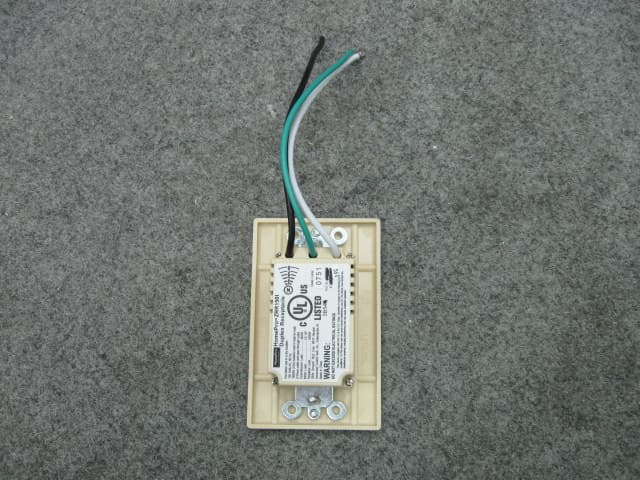
QIE0738-02
Jan 20, 2010Wireless Duplex Receptacle
Equipment Class
DXX - Part 15 Low Power Communication Device Transmitter