QIE0791-01Wireless Switch
Advanced Control Technologies, Inc.
Click to zoom
Application Details
- Equipment Class
- DXT - Part 15 Low Power Transceiver, Rx Verified
- Date of Grant
- Oct 27, 2010
- Application Purpose
- Original Equipment
- Date of Application
- Oct 27, 2010
- Equipment Note
- Wireless Switch
- Frequency Range
- 908.39000000 - 908.39000000
- Country
- United States
Documents & Files
Document Text
Text extracted from the exhibit documents filed with the FCC. Open a document above to read the original.
Users Manual
Evolve LRF-20 Instructions, Release 5.1 P/D 092610 EvolveNet by EvolvE GuEst Controls Radio Frequency (RF) Controlled, 120 VAC, Scene Capable, Isolated Contact Fixture Module, Release 5.1, 300 Series LRF-20 IsoLatEd CoNtaCt FIxtuRE ModuLE The LRF-20 Isolated Contact Fixture Module is a component of the Evolve lighting control system. Wire the Isolated Contact Fixture Module according to the diagram above and program it from the Wireless Controller to operate loads. Inclusion of this Switch on the EHC-100 Wireless Controller menu allows remote ON/OFF control of load connected. This Isolated Contact Fixture Module is designed to work with other Z-Wave enabled devices. Z-Wave nodes of other types can be included on the network and will also act as repeaters if they support this function. As part of a Z-Wave network, the LRF-20 will also act as a wireless repeater to insure that commands intended for another device in the network are received. This is useful when the device would otherwise be out of the radio range of the wireless controller. There are no field repairable assemblies on this unit.. If service is needed, the unit must be returned where purchased. daNGER! sHoCK HaZaRd. Read and understand these instructions before installing. This device is intended for installation in accordance with the National Electric code and local regulations in the United States, or the Canadian Electrical Code and local regulations in Canada. It is recommended that a qualified electrician perform this installation. For indoor use only. Retain instructions for future use. INstaLLatIoN Wire this module in series with a (maximum) 20 amp load according to the diagram above. AS101’s are required to be wired to the same line (or neutral) which is also wired to the master unit as well as the load being controlled, and not wired to any other neutral. If multiple neutrals are tied together in one box, separate the neutrals to preserve the integrity of the LRF-20 circuit. See the EHC-100 Wireless Controller operat- ing instructions to include this module under the command of the Wireless Controller. Fixture Mounted Configuration Push the button on the face to configure the module to operate from the wireless controller (see EHC-100 instructions). With the Wireless Controller, the LRF-20 can be switched ON and OFF remotely, and can be LRF-20 Evolve LRF-20 Instructions, Release 5.1 P/D 092610 EvolveNet by EvolvE GuEst Controls included in groups of lights that operate at the same time (a group can also be a single module), and in scenes that set a lighting mood. switch power on and oFF with Auxiliary switch The LRF-20 can also be controlled from an AS101 ver.2 auxiliary switch in another location. A second AS101v2 (maximum is two) can be wired in parallel with the first to create 4-way control. other functions The button on the LRF-20 also plays a role as a reset in addition to including the module in groups and scenes. This is described in more detail in the Wireless Controller instructions. over-current protection The LRF-20 is protected by an internal fuse. This internal fuse is factory serviceable only. Check your home circuit breakers before concluding that the product must be returned to manufacturer for repair at a nominal charge. Button (local Control) The button on the LRF-20 allows the user to • Turn the load attached ON or OFF. • Include or exclude the module in the Z-Wave system: stEP 1. Prepare the Controller to include a unit to the network by adding it to a group (method of adding a node to the network). Refer to controller instructions. stEP 2. the LRF-20 must be in its permanently installed location. • To add a node: Tap the button. • To remove a node: Tap the button 3 times, then press and hold (Ex. tap, tap, tap, hold) stEP 3. You should see an indication on your Controller that the “DEvICE WAS INCLUDED” or “DEvICE WAS EXCLUDED” in the network. If attached, an AS101 ver.2 auxiliary switch can also be used to Include or Exclude the module from the Z-Wave system. When a controller prompts you to “Send Node ID” or to “Press Button on Unit”, follow steps 1 through 3 above to satisfy those instructions. lED indication The LED on the LRF-20 will turn on when the load attached is ON. The LED can be user configured however to turn ON when the load attached is OFF, if so desired. The LRF-20 will flicker its LED when it is transmitting to any of its 4 groups. This can be changed if desired. remote Control The LRF-20 will respond to BASIC and BINARY and SCENE commands that are part of the Z-Wave system. Refer to your controller’s instructions as to whether your controller can transmit those commands. advaNCEd oPERatIoN All on/All off The LRF-20 supports the ALL ON/ ALL OFF commands. The LRF-20 can be set to respond to ALL ON and ALL OFF commands 4 different ways. Refer to your controller for information on how to set the LRF-20 to operate in the manner you desire. Some controllers may be only able to set certain settings of ALL ON/ALL OFF response. The 4 different ways the LRF-20 can be setup to respond to ALL ON and ALL OFF commands are: • LRF-20 will not respond to ALL ON or the ALL OFF command. • LRF-20 will respond to ALL OFF command but will not respond to ALL ON command. • LRF-20 will respond to ALL ON command but will not respond to ALL OFF command. • LRF-20 will respond to ALL ON and the ALL OFF command. Evolve LRF-20 Instructions, Release 5.1 P/D 092610 EvolveNet by EvolvE GuEst Controls sPECIFICatIoNs Power: 120 vAC, 50/60 Hz Signal (Frequency): 908.42 MHz Maximum Load Isolated Contacts: 20 amps G.P. maximum, 277 vAC, 10FLA, 60LRA, 250vAC, Motor: 1 H.P. maximum, 120/240 vAC Incandescent: Tv8 (Tungsten), 120 vAC, 960W maximum Range: Up to 100 feet line of sight between the Wireless Controller and /or the closest Evolve Receiver Module INtERoPERabILIty wItH Z-wavE™ dEvICEs A Z-Wave™ network can integrate devices of various classes, and these devices can be made by different manufacturers. The LRF-2…
Text truncated - open the document above for the full version.
Users Manual
ZRF113 Instructions, Release 5.1 P/D 081110 HomePro by ADVANCED CONTROL TECHNOLOGIES, INC. 0791-01 1 Radio Frequency (RF) Controlled, 120 VAC, Scene Capable, Isolated Contact Fixture Module, Release 5.1, 300 Series ZRF113 HomePro RF Home Automation ZRF113 ISOLATED CONTACT FIXTURE MODULE The ZRF113 Isolated Contact Fixture Module is a component of the HomePro lighting control system. Wire the Isolated Contact Fixture Module according to the diagram above and program it from the Wireless Controller to operate loads. Inclusion of this Switch on the ZTH100 Wireless Controller menu allows remote ON/OFF control of load connected. This Isolated Contact Fixture Module is designed to work with other Z-Wave enabled devices. Z-Wave nodes of other types can be included on the network and will also act as repeaters if they support this function. As part of a Z-Wave network, the ZRF113 will also act as a wireless repeater to insure that commands intended for another device in the network are received. This is useful when the device would otherwise be out of the radio range of the wireless controller. There are no field repairable assemblies on this unit.. If service is needed, the unit must be returned where purchased. DANGER! SHOCK HAZARD. Read and understand these instructions before installing. This device is intended for installation in accordance with the National Electric code and local regulations in the United States, or the Canadian Electrical Code and local regulations in Canada. It is recommended that a qualified electrician perform this installation. For indoor use only. Retain instructions for future use. INSTALLATION Wire this module in series with a (maximum) 20 amp load according to the diagram above. AS101’s are required to be wired to the same line (or neutral) which is also wired to the master unit as well as the load being controlled, and not wired to any other neutral. If multiple neutrals are tied together in one box, separate the neutrals to preserve the integrity of the ZRF113 circuit. See the ZTH100 Wireless Controller operating instructions to include this module under the command of the Wireless Controller. Fixture Mounted Configuration Push the button on the face to configure the module to operate from the wireless controller (see ZTH100 instruc- tions). With the Wireless Controller, the ZRF113 can be switched ON and OFF remotely, and can be included ZRF113 Instructions, Release 5.1 P/D 081110 HomePro by ADVANCED CONTROL TECHNOLOGIES, INC. 0791-01 2 in groups of lights that operate at the same time (a group can also be a single module), and in scenes that set a lighting mood. Switch power ON and OFF with Auxiliary Switch The ZRF113 can also be controlled from an AS101 ver.2 auxiliary switch in another location. A second AS101v2 (maximum is two) can be wired in parallel with the first to create 4-way control. Other functions The button on the ZRF113 also plays a role as a reset in addition to including the module in groups and scenes. This is described in more detail in the Wireless Controller instructions. Over-current protection The ZRF113 is protected by an internal fuse. This internal fuse is factory serviceable only. Check your home circuit breakers before concluding that the product must be returned to manufacturer for repair at a nominal charge. Button (Local Control) The button on the ZRF113 allows the user to • Turn the load attached ON or OFF. • Include or exclude the module in the Z-Wave system: STEP 1. Prepare the Controller to include a unit to the network by adding it to a group (method of adding a node to the network). Refer to controller instructions. STEP 2. The ZRF113 must be in its permanently installed location. • To add a node: Tap the button. • To remove a node: Tap the button 3 times, then press and hold (Ex. tap, tap, tap, hold) STEP 3. You should see an indication on your Controller that the “DEVICE WAS INCLUDED” or “DEVICE WAS EXCLUDED” in the network. If attached, an AS101 ver.2 auxiliary switch can also be used to Include or Exclude the module from the Z-Wave system. When a controller prompts you to “Send Node ID” or to “Press Button on Unit”, follow steps 1 through 3 above to satisfy those instructions. LED indication The LED on the ZRF113 will turn on when the load attached is ON. The LED can be user configured however to turn ON when the load attached is OFF, if so desired. The ZRF113 will flicker its LED when it is transmitting to any of its 4 groups. This can be changed if desired. Remote Control The ZRF113 will respond to BASIC and BINARY and SCENE commands that are part of the Z-Wave system. Refer to your controller’s instructions as to whether your controller can transmit those commands. ADVANCED OPERATION All On/All Off The ZRF113 supports the ALL ON/ ALL OFF commands. The ZRF113 can be set to respond to ALL ON and ALL OFF commands 4 different ways. Refer to your controller for information on how to set the ZRF113 to operate in the manner you desire. Some controllers may be only able to set certain settings of ALL ON/ALL OFF response. The 4 different ways the ZRF113 can be setup to respond to ALL ON and ALL OFF commands are: • ZRF113 will not respond to ALL ON or the ALL OFF command. • ZRF113 will respond to ALL OFF command but will not respond to ALL ON command. • ZRF113 will respond to ALL ON command but will not respond to ALL OFF command. • ZRF113 will respond to ALL ON and the ALL OFF command. ZRF113 Instructions, Release 5.1 P/D 081110 HomePro by ADVANCED CONTROL TECHNOLOGIES, INC. 0791-01 3 SPECIFICATIONS Power: 120 VAC, 50/60 Hz Signal (Frequency): 908.42 MHz Maximum Load Isolated Contacts: 20 amps G.P. maximum, 277 VAC, 10FLA, 60LRA, 250VAC, Motor: 1 H.P. maximum, 120/240 VAC Incandescent: TV8 (Tungsten), 120 VAC, 960W maximum Range: Up to 100 feet line of sight between the Wireless Controller and /or the closest HomePro Receiver Module INTEROPERABILITY WITH Z-WAVE™ DEVICES A Z-Wave™ network can integrate devices of various class…
Text truncated - open the document above for the full version.
External Photos
External photo Front View of the product Rear View of the product Side View of the product Side View of the product Top View of the product Bottom View of the product Label location
Internal Photos
Internal photo Inner View of the product Inner Circuit Top View Inner Circuit Bottom View Inner Circuit Top View Inner Circuit Bottom View Antenna
Test Report
TEST REPORT No: (5210)244-0584 BUREAU VERITAS HONG KONG LIMITED – Kowloon Bay Office 1/F Pacific Trade Centre, 2 Kai Hing Road, Kowloon Bay, Kowloon,HONG KONG Tel: +852 2331 0888 Fax: +852 2331 0889 www.cps.bureauveritas.com This report is intended for your exclusive use. Any copying or replication of this report to or for any other person or entity, or use of our name or trademark, is permitted only with our prior written permission. Our report is limited to the test samples identified herein. The results set forth in this report are not necessarily indicative or representative of the statistical quality or characteristics of the lot from which a test sample was taken or any similar or identical product unless specifically and expressly noted. Our report includes all of the tests requested by you and the results thereof. You shall have thirty days from receipt of this report to request additional testing of the samples or to notify us of any errors or omissions relating to our report, provided, however, such notice shall be in writing and shall specifically address the issue you wish to raise. A failure to raise such issue within the prescribed time shall constitute your unqualified acceptance of the completeness of this report, the tests conducted and the correctness of the report contents. Page 2 of 25 Location of the test laboratory Radiated and Conducted emissions measurements are investigated and taken pursuant to the procedures of ANSI C63.4 – 2003. An Open Area Test Site and Full Anechoic Chamber (FCC Listed Site, Registration No. 642151) are set up for investigation and located at : BUREAU VERITAS HONG KONG LIMITED, EMC CENTRE No. 2106-2107, 21/F., Westin Centre, 26 Hung To Road, Kwun Tong, Kowloon, Hong Kong List of measuring equipment Radiated Emission EQUIPMENT MANUFACTURER MODEL NO. SERIAL NO. CALIBRATION DUE EMI TEST RECEIVER R&S ESCS 30 830986/030 26-SEP-2010 BILOG ANTENNA SCHAFFNER CBL6112D 25229 02-AUG-2011 OPEN AREA TEST SITE BVCPS N/A N/A 05-JULY-2011 ANECHOIC CHAMBER ALBATROSS M-CDC 80374004499B 06-JULY-2011 HORN ANTENNA SCHWARZBECK BBHA9120D 9120D-692 20-JULY-2011 PREAMPLIFIER SCHWARZBECK BBV9718 9718-152 26-JULY-2011 COAXIAL CABLE SUHNER N/A N/A 07-DEC-2010 Conducted Emission EQUIPMENT MANUFACTURER MODEL NO. SERIAL NO. CALIBRATION DUE EMI TEST RECEIVER R&S ESCS 30 830986/030 26-SEP-2010 LISN R&S ENV216 100024 09-MAR-2011 Remarks:- N/A : Not Applicable or Not Available The measurement instrumentation uncertainty would be taking into consideration on each of the test result TEST REPORT No: (5210)244-0584 BUREAU VERITAS HONG KONG LIMITED – Kowloon Bay Office 1/F Pacific Trade Centre, 2 Kai Hing Road, Kowloon Bay, Kowloon,HONG KONG Tel: +852 2331 0888 Fax: +852 2331 0889 www.cps.bureauveritas.com This report is intended for your exclusive use. Any copying or replication of this report to or for any other person or entity, or use of our name or trademark, is permitted only with our prior written permission. Our report is limited to the test samples identified herein. The results set forth in this report are not necessarily indicative or representative of the statistical quality or characteristics of the lot from which a test sample was taken or any similar or identical product unless specifically and expressly noted. Our report includes all of the tests requested by you and the results thereof. You shall have thirty days from receipt of this report to request additional testing of the samples or to notify us of any errors or omissions relating to our report, provided, however, such notice shall be in writing and shall specifically address the issue you wish to raise. A failure to raise such issue within the prescribed time shall constitute your unqualified acceptance of the completeness of this report, the tests conducted and the correctness of the report contents. Page 3 of 25 Equipment Under Test [EUT] Description of Sample: Model Name: FIXTURE MODULE RECEIVER Model Number: ZRF113 Series 300 Additional Model Number: LRF-20 Additional Model information: Declare the Circuit, PCB layout, Electrical parts and outlook of the products are identical to the basic model, except the model number. Rating: 120Va.c, 60Hz Description of EUT Operation: The Equipment Under Test (EUT) is an ADVANCED CONTROL TECHNOLOGIES, INC. of RF Fixture Module. The transceiver is 1 button on/off function and operating at 908.40MHz. The transmission occurs briefly in response to one of two events: 1) A manually issued command initiated by the User via a remote control, or 2) An automated command that is initiated when the internal time of day clock matches a previously User- programmed time. Modulation by IC, and type is FSK modulation. The transmitter has different control: 1. On/Off button – on/off control Antenna Requirement (Section 15.203) The EUT is use of a permanently antenna. The antenna consists of 8cm long wire. It is soldered on the PCB. The antenna is not replaceable or user serviceable. The requirements of S15.203 are met. There are no deviations or exceptions to the specifications. TEST REPORT No: (5210)244-0584 BUREAU VERITAS HONG KONG LIMITED – Kowloon Bay Office 1/F Pacific Trade Centre, 2 Kai Hing Road, Kowloon Bay, Kowloon,HONG KONG Tel: +852 2331 0888 Fax: +852 2331 0889 www.cps.bureauveritas.com This report is intended for your exclusive use. Any copying or replication of this report to or for any other person or entity, or use of our name or trademark, is permitted only with our prior written permission. Our report is limited to the test samples identified herein. The results set forth in this report are not necessarily indicative or representative of the statistical quality or characteristics of the lot from which a test sample was taken or any similar or identical product unless specifically and expressly noted. Our report includes all of the tests requested by you and the results thereof. You shall have thirty days from receipt of this report to request additional testing of…
Text truncated - open the document above for the full version.
Test Setup Photos
Conducted Emission Test Set Up Radiated Emission Test Set Up
Contact Information
Applicant
Josh Hansen(Regulatory Engineer)
Test Firm
Bureau Veritas Hong Kong LimitedSteven Tsang
[email protected]85223310728
Technical Specifications
| # | Rule Parts | Frequency Range | Power Output |
|---|---|---|---|
| 1 | 15C | 908.39 MHz - 908.39 MHz | - |
Other Applications from Advanced Control Technologies, Inc.

QIE0810-01
Oct 20, 2011Dimmer
Equipment Class
DXT - Part 15 Low Power Transceiver, Rx Verified
QIE0792-01
Aug 24, 2010Wall Mounted Dimmer
Equipment Class
DXT - Part 15 Low Power Transceiver, Rx Verified
QIE0797-01
Jul 21, 2010Wall Mounted Dimmer
Equipment Class
DXT - Part 15 Low Power Transceiver, Rx Verified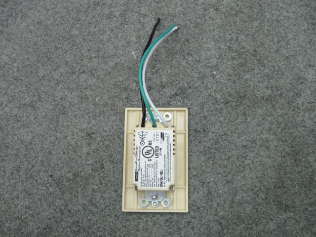
QIE0738-02
Jan 20, 2010Wireless Duplex Receptacle
Equipment Class
DXX - Part 15 Low Power Communication Device Transmitter
QIE0763-03
Jan 12, 2010Wireless Switch
Equipment Class
DXX - Part 15 Low Power Communication Device Transmitter