QIE0685-0XHomePro Wall Mounted Infrared Sensor
Advanced Control Technologies, Inc.
Click to zoom
Application Details
- Equipment Class
- DXT - Part 15 Low Power Transceiver, Rx Verified
- Date of Grant
- Jun 02, 2005
- Application Purpose
- Original Equipment
- Date of Application
- Jun 02, 2005
- Equipment Note
- HomePro Wall Mounted Infrared Sensor
- Frequency Range
- 908.39000000 - 908.39000000
- Country
- United States
Documents & Files
Document Text
Text extracted from the exhibit documents filed with the FCC. Open a document above to read the original.
Users Manual
ZIR000 Instructions P/D 092704 HomePro by ADVANCED CONTROL TECHNOLOGIES, INC. 0685-01 1 Radio Frequency Transmitter, Battery Powered, Wall Mounted Passive Infrared (PIR) Sensor ZIR000 HomePro RF Home Automation Shown with supplied wall mount bracket ZIR000 WALL MOUNTED SENSOR The ZIR000 Wall Mounted Sensor is a component of the HomePro lighting control system. Inclusion of this Wall Mounted Sensor on the ZTH100 Wireless Controller menu allows remote ON/OFF control HomePro receivers to control lighting. Z-Wave nodes of other types can be added to the system and will also act as repeaters if they support this function of repeating the signal received to other modules in the system. There are no field repairable assemblies on this unit. It is covered by a one year limited warranty. If service is needed, the unit must be returned where purchased. CAUTION! Read and understand these instructions before installing. For indoor use only. Retain instructions for future use. INSTALLATION Battery Installation and Sensitivity Selection 1. Remove the screw from the bottom of the enclosure. 3. Select the sensitivity setting preferred for the ZIR000 by setting the corresponding jumpers on the electronic module. Note that H option is the highest sensitivity while the L option is the lowest. See Figure 1. Mounting Location The ZIR000 is designed for indoor use. It should not be mounted near large metal objects or on metal sur- faces. It should be mounted on a wall or in a corner at a height of approximately 6.5 to 8.2 feet (2 to 2.5 meters) for the best general coverage in an average room. The detector has been designed to avoid false alarms, nevertheless, it is best to avoid looking directly at sources of heat such as fires and boilers, and always try to keep away from a window. The ZIR000 can be positioned across from a radiator but not placed above one. Do not mount the ZIR000 where its field of view may be obstructed (e.g. by curtains). 39 foot (12 m) range, 110 degree coverage with convex honeycomb hemispherical infra-red lens Fig. 1 ZIR000 Instructions P/D 092704 HomePro by ADVANCED CONTROL TECHNOLOGIES, INC. 0685-01 2 Mounting the Detector 1. Place the provided ZIR000 mounting bracket into the location you want to mount it. Mark the wall (or ceiling) where the two screw holes are that will be used. 2. Complete the following two steps if mounting in drywall, where there is not a stud. a. Drill a pilot hole of 11/64”. b. Tap the provided wall anchors into the wall (or ceiling). 3. Screw the mounting bracket to the wall (or ceiling). 4. Install the four AA batteries into the ZIR000 and snap the ZIR000 onto the mounting bracket. 5. Adjust the vertical pattern angle per figure 2, if desired. Fig 2 LENS can be adjusted to suit your needs by simply rotating the angle of the lens 180 o to change from wide angle version (Default setting) to long range version if required. WIDE ANGLE Angle: 105 o x 110 o Distance: 39 feet (12 meters) Zone Number: 64 Default Setting LONG RANGE Angle: 5 o x 5 o Distance: 14m Zone Number: 8 Default Setting + 180 o Walk Test (checking the detection field) 3. Place the LED jumper in the “On” location. See figure 3. 4. Replace the top enclosure and screw. 5. Walk slowing across the field of view (Back and Forth) and observe the LED – it lights whenever you enter or exit a sensitive beam. Allow 5 seconds after the LED has lit to continue the test, this is so the unit can stabilize. 6. After testing, remove the retaining screw and the top of the enclosure and and set the LED jumper back to the off position. 7. Replace top enclosure and retaining screw. ZIR000 Instructions P/D 092704 HomePro by ADVANCED CONTROL TECHNOLOGIES, INC. 0685-01 3 PowerFour (4) AAA batteries MountingMounting bracket provided Signal (Frequency)908.42 MHz RangeUp to 100 feet line of sight between the Wireless Controller and /or the Mounted Dimensions (H x W x D)4.125” x 2.6” x 3.10” (10.47cm x 6.6cm x 7.8 cm) closest HomePro Reciever Module WARRANTY For warranty and general product information visit our web site at www.act-solutions.com ABOUT ZIR000’S CERTIFICATION The ZIR000 has been thoroughly tested by the ETL SEMCO division of Intertek, a nationally recognized testing laboratory. This product was found to be in compliance with safety standards ANSI/ UL STD 244A and CAN/CSA C22.2 No. 177. In addition to compliance with product safety standards, the ZIR000 is also certified to comply with applicable FCC and IC rules and regulations governing RF and EMI emissions. This device complies with part 15 of the FCC Rules. Operation is subject to the following two conditions: (1) This device may not cause harmful interference, and (2) This device must accept any interference received, including interference that may cause undesired operation. FCC NOTICE Note: This equipment has been tested and found to comply with the limits for a Class B digital device, pursuant to part 15 of the FCC Rules. These limits are designed to provide reasonable protection against harmful interference in a residential installation. This equipment generates, uses, and can radiate radio frequency energy and, if not installed and used in accordance with the instructions may cause harmful interference to radio communications. However, there is no guarantee that interference will not occur in a particular installation. If this equipment does cause harmful interfer- ence to radio or television reception, which can be determined by turning the equipment off and on, the user is encour- aged to try to correct the interference by one or more of the following measures: - Increase the separation between the equipment and receiver. - Consult the dealer or an experienced radio/TV technician for help. IC NOTICE This Class B digital apparatus complies with Canadian ICES-003. Cet appareil numérique de la classe B est conforme à la norme NMB-003 du Canada. Operation is subject to the following two conditions: (1) this device may not cause interference, and (…
Text truncated - open the document above for the full version.
ID Label/Location Info
ZIR000 Label Artwork Radius corners of label 1/8” (or .125”) HomePro ZIR000 RF Transmitter PIR 908.42MHz Serial # Four (4) AAA Batteries Required Made in China FCC ID - QIE0685-0X Canada IC: 4436A-06850X PRODUCT LABEL To be made from 80Y (UL file PGDQ2.MH13653) or equvalent. Must comply with UL969.
Operational Description
0718R1A.doc 1/10/2005 1:26 PM Page 1 of 1 Advanced Control Technologies, Inc. Technical Description Project: AZM1207-RE US Project No.: 0718-01 Project Engineer: Chad Snead Technical Description: The AZM1207-RE US is a transceiver module that can be used with different applications. The transceiver operates in half-duplex fashion to provide two-way communications with other devices. The communications, while varied, most often consist of a command from the remote control followed by an acknowledgement by the addressed module(s) that a valid command was received. The transceiver operates in the 900MHz ISM band at 908.42 MHz. The data, which is digital in nature, is Manchester encoded and sent using FSK modulation at a 9600 bit/sec rate. The deviation of the modulation is plus and minus 15 KHz A 7.376974 MHz crystal oscillator is used both as a clock for the micro-controller and a reference oscillator for the fractional PLL frequency synthesizer portions of the ASIC. This PLL is used to generate both the local oscillator for the receiver and the fundamental frequency of the transmitter. The output power of the transmitter portion of the transceiver is controlled by the microcontroller which causes the transmit power to be very low for some setup functions. Modulation of the transmitter is accomplished in the PLL by having the microcontroller cause it to use one divisor when the binary modulating data is zero (low) and a slightly different one, when it is one (high). The receiver is a single conversion type. The local oscillator runs at 908.275 MHz (145 KHz below the receive frequency). A wireless transmission occurs briefly in response to one of two events: 1) A manually issued command initiated by the User via a remote control, or 2) An automated command that is initiated when the internal time of day clock matches a previously User-programmed time. The communications are done using a protocol called the Z-Wave protocol, a wireless network protocol that was designed especially for home automation applications. It defines how various types of information are to be formatted into frames. These frames not only include commands and data, but also source and destination information, as well as checksums that are used for error detection. The AZM1207-RE US and accompanying application board, the remote control, and other modules make up a wireless local network, where each of the modules can function as wireless repeaters (also half duplex). There is provision within the protocol for intelligent and adaptive routing and for the handling of collisions. Except for a handful of discrete passive components, the entire transceiver is contained in the ASIC, the ZW0102 made by Zensys. The transmitter and receiver share a common antenna. A SAW filter is used to help minimize receiver overload from strong signals on nearby frequencies and to attenuate any undesired harmonics from the transmitter. The antenna used in the AZM1207-RE US is a wire antenna. There are no external connections to the antenna
Test Report
CONTENTS 1.0 GENERAL DESCRIPTION ....................................................................................................... 1 1.1 Related Submittals Grants................................................................................................................ 1 1.2 Product Description ......................................................................................................................... 1 1.3 Test Methodology ............................................................................................................................ 1 1.4 Test Facility ..................................................................................................................................... 1 2.0 SYSTEM TEST CONFIGURATION....................................................................................... 2 2.1 Justification ...................................................................................................................................... 2 2.2 EUT Setup........................................................................................................................................ 2 2.3 EUT Exercising Software ................................................................................................................ 2 2.4 Special Accessories.......................................................................................................................... 2 2.5 Equipment Modification .................................................................................................................. 2 2.6 Support Equipment List and Description.........................................................................................2 2.7 Test Configuration Block Diagrams ................................................................................................ 3 3.0 TEST RESULTS ........................................................................................................................... 4 3.1 Field Strength of Fundamental and Harmonics Emissions, FCC 15.249(a)(b), 15.205 .................. 5 3.2 Out of Band Spurious Emissions ..................................................................................................... 7 3.3 Bandwidth of Emissions .................................................................................................................. 8 3.4 Radiated Emissions, FCC 15.109, Class B .................................................................................... 10 3.5 Test Procedure ............................................................................................................................... 11 3.6 Field Strength Calculation ............................................................................................................. 12 4.0 TEST EQUIPMENT.................................................................................................................. 13 FCC ID: QIE0685-0X Report No. 3076910.011 Page 1 of 13 1.0 GENERAL DESCRIPTION 1.1 Related Submittals Grants This is single application of the Advanced Control Technologies Inc. ZIR000 Motion Sensor Certification under FCC Part 15, Subpart C. There are no other simultaneous applications. 1.2 Product Description The ZIR000 Motion Sensor is a RF transmitter operating in 908.39MHz. The intended use of the ZIR000 Motion Sensor is to generate and transmit a RF signal to activate load receiver. ZIR000 Motion Sensor is powered at 6VDC AAA internal batteries. Antenna Description: Single isolated wire 9cm length soldered to the RF Board inside the unit Sample Submitted: May 9, 2005 Test Work Started: May 9, 2005 Test Work Completed: May 12, 2005 1.3 Test Methodology Emission measurements were performed according to the procedures in ANSI C63.4-2001. All field strength radiated emissions measurements were performed in the semi-anechoic chamber, and for each scan, the procedure for maximizing emissions in Appendices D and E were followed. All field strength radiated tests were performed at an antenna to EUT distance of 3 meters, unless stated otherwise in the "Justification Section" of this Application. 1.4 Test Facility The test site facility used to collect the radiated and conducted measurement data is located at 7250 Hudson Blvd., Suite 100, Oakdale, Minnesota. This test facility has been fully described in a report dated on March 2003 submitted to FCC. Please reference the site registration number: 90706, dated April 18, 2003. FCC ID: QIE0685-0X Report No. 3076910.011 Page 2 of 13 2.0 SYSTEM TEST CONFIGURATION 2.1 Justification Line Conducted Emissions testing is inappropriate and therefore unnecessary as batteries power the equipment. 2.2 EUT Setup For simplicity of testing, the transmitter was setup to transmit continuously for spurious emissions testing. 2.3 EUT Exercising Software N/A 2.4 Special Accessories There are no special accessories necessary for compliance of these products. Cables N/A 2.5 Equipment Modification No modifications were installed during the testing. 2.6 Support Equipment List and Description N/A FCC ID: QIE0685-0X Report No. 3076910.011 Page 3 of 13 2.7 Test Configuration Block Diagrams The EUT was setup as tabletop equipment. The EUT was powered at 6VDC form new internal AAA batteries. Field Strength Measurements For simplicity of testing, the Unit was set to transmit continuously for spurious emissions measurements. FCC ID: QIE0685-0X Report No. 3076910.011 Page 4 of 13 3.0 TEST RESULTS Data is included for the worst-case configuration (the configuration which resulted in the highest emission levels). A sample calculation, configuration photographs, data tables and graphical representations of the emissions are included. The EUT is intended for operation under the requirements of Part 15 Subpart C. Specific test requirements include the following: 47 CFR 15.249(a)(b) Field Strength of Fundamental 47 CFR 15.249(a)(b), 15.205 Field Strength of Harmonics 47 CFR 15.249(…
Text truncated - open the document above for the full version.
Test Report
CONTENTS 1.0 GENERAL DESCRIPTION ....................................................................................................... 1 1.1 Related Submittals Grants................................................................................................................ 1 1.2 Product Description ......................................................................................................................... 1 1.3 Test Methodology ............................................................................................................................ 1 1.4 Test Facility ..................................................................................................................................... 1 2.0 SYSTEM TEST CONFIGURATION....................................................................................... 2 2.1 Justification ...................................................................................................................................... 2 2.2 EUT Setup........................................................................................................................................ 2 2.3 EUT Exercising Software ................................................................................................................ 2 2.4 Special Accessories.......................................................................................................................... 2 2.5 Equipment Modification .................................................................................................................. 2 2.6 Support Equipment List and Description.........................................................................................2 2.7 Test Configuration Block Diagrams ................................................................................................ 3 3.0 TEST RESULTS ........................................................................................................................... 4 3.1 Field Strength of Fundamental and Harmonics Emissions, FCC 15.249(a)(b), 15.205 .................. 5 3.2 Out of Band Spurious Emissions ..................................................................................................... 7 3.3 Bandwidth of Emissions .................................................................................................................. 8 3.4 Radiated Emissions, FCC 15.109, Class B .................................................................................... 10 3.5 Test Procedure ............................................................................................................................... 11 3.6 Field Strength Calculation ............................................................................................................. 12 4.0 TEST EQUIPMENT.................................................................................................................. 13 FCC ID: QIE0685-0X Report No. 3076910.011 Page 1 of 13 1.0 GENERAL DESCRIPTION 1.1 Related Submittals Grants This is single application of the Advanced Control Technologies Inc. ZIR000 Motion Sensor Certification under FCC Part 15, Subpart C. There are no other simultaneous applications. 1.2 Product Description The ZIR000 Motion Sensor is a RF transmitter operating in 908.39MHz. The intended use of the ZIR000 Motion Sensor is to generate and transmit a RF signal to activate load receiver. ZIR000 Motion Sensor is powered at 6VDC AAA internal batteries. Antenna Description: Single isolated wire 9cm length soldered to the RF Board inside the unit Sample Submitted: May 9, 2005 Test Work Started: May 9, 2005 Test Work Completed: May 12, 2005 1.3 Test Methodology Emission measurements were performed according to the procedures in ANSI C63.4-2001. All field strength radiated emissions measurements were performed in the semi-anechoic chamber, and for each scan, the procedure for maximizing emissions in Appendices D and E were followed. All field strength radiated tests were performed at an antenna to EUT distance of 3 meters, unless stated otherwise in the "Justification Section" of this Application. 1.4 Test Facility The test site facility used to collect the radiated and conducted measurement data is located at 7250 Hudson Blvd., Suite 100, Oakdale, Minnesota. This test facility has been fully described in a report dated on March 2003 submitted to FCC. Please reference the site registration number: 90706, dated April 18, 2003. FCC ID: QIE0685-0X Report No. 3076910.011 Page 2 of 13 2.0 SYSTEM TEST CONFIGURATION 2.1 Justification Line Conducted Emissions testing is inappropriate and therefore unnecessary as batteries power the equipment. 2.2 EUT Setup For simplicity of testing, the transmitter was setup to transmit continuously for spurious emissions testing. 2.3 EUT Exercising Software N/A 2.4 Special Accessories There are no special accessories necessary for compliance of these products. Cables N/A 2.5 Equipment Modification No modifications were installed during the testing. 2.6 Support Equipment List and Description N/A FCC ID: QIE0685-0X Report No. 3076910.011 Page 3 of 13 2.7 Test Configuration Block Diagrams The EUT was setup as tabletop equipment. The EUT was powered at 6VDC form new internal AAA batteries. Field Strength Measurements For simplicity of testing, the Unit was set to transmit continuously for spurious emissions measurements. FCC ID: QIE0685-0X Report No. 3076910.011 Page 4 of 13 3.0 TEST RESULTS Data is included for the worst-case configuration (the configuration which resulted in the highest emission levels). A sample calculation, configuration photographs, data tables and graphical representations of the emissions are included. The EUT is intended for operation under the requirements of Part 15 Subpart C. Specific test requirements include the following: 47 CFR 15.249(a)(b) Field Strength of Fundamental 47 CFR 15.249(a)(b), 15.205 Field Strength of Harmonics 47 CFR 15.249(…
Text truncated - open the document above for the full version.
Contact Information
Applicant
Josh Hansen(Regulatory Engineer)
Technical Contact
Advanced Control TechnologiesChad Snead
[email protected]317-337-0100
8076 Woodland Drive · Indianapolis, Indiana · United States
Non-Technical Contact
Advanced Control TechnologiesJeff Bex
[email protected]317-337-0100
Test Firm
Intertek Testing ServicesUri Spector
Technical Specifications
| # | Rule Parts | Frequency Range | Power Output |
|---|---|---|---|
| 1 | 15C | 908.39 MHz - 908.39 MHz | - |
Other Applications from Advanced Control Technologies, Inc.

QIE0810-01
Oct 20, 2011Dimmer
Equipment Class
DXT - Part 15 Low Power Transceiver, Rx Verified
QIE0791-01
Oct 27, 2010Wireless Switch
Equipment Class
DXT - Part 15 Low Power Transceiver, Rx Verified
QIE0792-01
Aug 24, 2010Wall Mounted Dimmer
Equipment Class
DXT - Part 15 Low Power Transceiver, Rx Verified
QIE0797-01
Jul 21, 2010Wall Mounted Dimmer
Equipment Class
DXT - Part 15 Low Power Transceiver, Rx Verified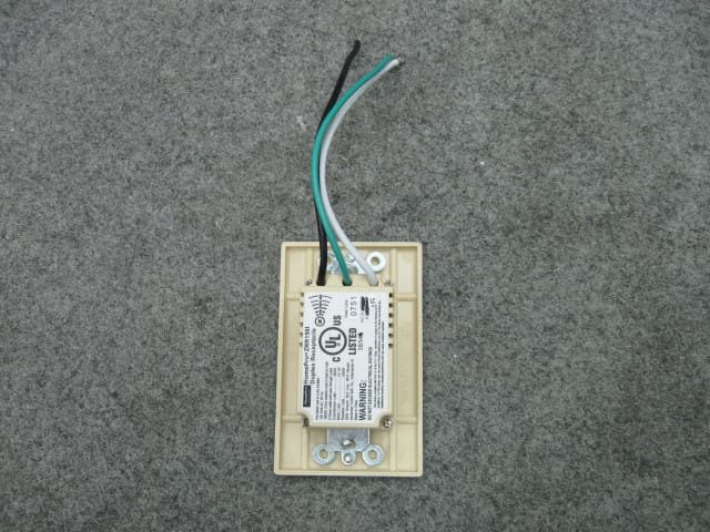
QIE0738-02
Jan 20, 2010Wireless Duplex Receptacle
Equipment Class
DXX - Part 15 Low Power Communication Device Transmitter