QIE06X8-0XHomePro Wall Switch/Dimmer
Advanced Control Technologies, Inc.
Click to zoom
Application Details
- Equipment Class
- DXT - Part 15 Low Power Transceiver, Rx Verified
- Date of Grant
- Aug 28, 2003
- Application Purpose
- Original Equipment
- Date of Application
- Aug 28, 2003
- Equipment Note
- HomePro Wall Switch/Dimmer
- Frequency Range
- 908.42000000 - 908.42000000
- Country
- United States
Documents & Files
Document Text
Text extracted from the exhibit documents filed with the FCC. Open a document above to read the original.
Users Manual
ZDW100 Instructions 082703 HomePro by ADVANCED CONTROL TECHNOLOGIES, INC. 0618-01 1 Radio Frequency Controlled, 300W, 120 VAC, Wall Mounted Dimmer Switch ZDW100 ZDW100 WALL MOUNTED DIMMER The ZDW100 Wall Mounted Dimmer is a component of the HomePro lighting control system. Wire the Wall Mounted Dimmer in place of the standard wall switch according to the diagram above and program from the Wireless Controller to operate loads. Inclusion of the Wall Mounted Dimmer on the ZTH100 Wireless Controller menu allows remote ON/OFF control and dimming of light connected. This Wall Mounted Dimmer is designed to work with other HomePro lamp and appliance controls. Z-Wave nodes of other types can be added to the system and will also act as repeaters if they support this function of repeating the signal received to other modules in the system. As part of a HomePro network, the ZDW100 will also act as a wireless repeater to insure that commands intended for another device in the network are received. This is useful when the device would otherwise be out of the radio range of the wireless controller. There are no field repairable assemblies on this unit. It is covered by a one year limited warranty. If service is needed, the unit must be returned where purchased. CAUTION! Read and understand these instructions before installing. This device is intended for installation in accordance with the National Electric code and local regulations in the United States, or the Canadian Electrical Code and local regulations in Canada. It is recommended that a qualified electrician perform this installation. To reduce the risk of overheating and possible damage to other equipment, do not install to control a receptacle, a motor operated appliance, a fluorescent lighting fixture, or a transformer-supplied appliance, but only permanently installed incandescent lamp fixtures. Make sure the lamp(s) to be controlled directly from the dimmer switch total no more than 300 watts. Retain instructions for future use. INSTALLATION CAUTION! - SHOCK HAZARD. Make all connections with the POWER OFF to avoid injury to the installer or damage to the device. 1. Strip 3/4" of insulation from the ends of the conductors (if not already done) and make connec- tions as shown in the Wiring Diagram. 2. Check connections to be sure they are tight and no bare conductors are exposed. 3. Make sure the load or installation does not exceed the device rating. 4. Install into an appropriately sized electrical switch box. Scored tabs on both sides can be bent up and down their length with pliers to break off, to allow fitting in a variety of electrical box types. 5. Restore the power.. HomePro RF Home Automation Shown with user supplied Decora TM trim plate ZDW100 Instructions P/D 082703 HomePro by ADVANCED CONTROL TECHNOLOGIES, INC. 0618-01 2 Wire this Wall Mounted Dimmer in place of a current wall switch according to the diagram. Refer to the Wireless Controller operating instructions to add this module under the command of the Wireless Controller. Wall Mounted Dimmer Configuration The Wall Mounted Dimmer switch locally controls the load ON and OFF. Adjust its dimming level by pressing and holding the top of the switch for Brighten, press and hold the bottom of the switch for Dim. Push on the top or the bottom of the switch to configure the module to operate from the wireless controller. With the Wireless Controller, the Wall Mounted Dimmer can be switched ON and OFF remotely, dimmed remotely and can be included in groups of lights that operate at the same time (a group can also be a single module), and in scenes that set a lighting mood. Switch power ON and OFF locally When the switch is pressed on the top the power will turn ON if off. Press the bottom of the switch and the power will turn OFF if it was on. Dimming If the bottom of the switch is pressed and held the light will dim. When the top is pressed and held, the light will brighten. Child Protection The Wall Mounted Dimmer can be set in a child protect mode by the Wireless Controller. When this mode is active, a user will have to press the Wall Mounted Dimmer 3 times rapidly to activate the attached load. The module operates normally when controlled by the Wireless Controller.. Other functions The switch on the Wall Mounted Dimmer also plays a role as a reset in addition to adding module to groups and scenes. This is described in more detail in the Wireless Controller instructions. Air Gap Switch The ZDW100 has an air gap switch on the face (lower left), that when pulled out, completely removes the power available to the load (more so than simply turning the dimmer off). This enables the lamps that are controlled by the device to be changed with minimal danger of electrical shock. The air gap switch must be pushed all the way back in for the dimmer to operate the lamps again. Software fuse This Wall Mounted Dimmer is designed to protect itself against loads that exceed it’s maximum power rating. The application of a load that exceeds that rating is quickly sensed by the dimmer and it responds by immediately shutting off all power to that load. If the dimmer doesn’t seem to work, or only works momentarily, check to see that the total lamp wattage doesn’t exceed the 300W rating of the dimmer. If a properly sized load is restored to the dimmer, it can be operated normally once again. Over-current protection The Wall Mounted Dimmer hardware also has an over current detection circuit as final protection against overload. If the software fuse should fail to shut down the dimmer when overloaded, backup protection is provided by an internal fuse. This internal fuse is not user serviceable. Check your home circuit breakers before concluding that the product must be returned to manufacturer for repair at a nominal charge. Operation Note When a light bulb reaches the end of it’s life and burns out, it sometimes creates a momentary short circuit. The high current that results may cause the dimmer to pro…
Text truncated - open the document above for the full version.
Users Manual
ZRW100 Instructions 082703 HomePro by ADVANCED CONTROL TECHNOLOGIES, INC. 0618-01 1 Radio Frequency Controlled, 300W, 120 VAC, Wall Mounted Switch ZRW100 HomePro RF Home Automation Shown with user supplied Decora TM trim plate ZRW100 WALL MOUNTED SWITCH The ZRW100 Wall Mounted Switch is a component of the HomePro lighting control system. Wire the Wall Mounted Switch in place of the standard wall switch according to the diagram above and program from the Wireless Controller to operate loads. Inclusion of this Wall Mounted Switch on the ZTH100 Wireless Controller menu allows remote ON/ OFF control of lamps connected. This Wall Mounted Switch is designed to work with other HomePro lamp and appliance controls. Z-Wave nodes of other types can be added to the system and will also act as repeaters if they support this function of repeating the signal received to other modules in the system. As part of a HomePro network, the ZRW100 will also act as a wireless repeater to insure that commands intended for another device in the network are received. This is useful when the device would otherwise be out of the radio range of the wireless controller. There are no field repairable assemblies on this unit. It is covered by a one year limited warranty. If service is needed, the unit must be returned where purchased. CAUTION! Read and understand these instructions before installing. This device is entended for installation in accordance with the National Electric code and local regulations in the United States, or the Canadian Electrical Code and local regulations in Canada. It is recommended that a qualified electrician perform this installation. Make sure the load controlled the switch does not exceed 1800 watts. For indoor use only. Retain instructions for future use. INSTALLATION Wire this Wall Mounted Switch in place of a current wall switch according to the diagram above. Refer to the Wireless Controller operating instructions to add this module under the command of the Wireless Controller. Wall Mounted Switch Configuration The Wall Mounted Switch locally controls the load ON and OFF. A push on the top or bottom of the paddle switch is used to configure the module to operate from the wireless controller. With the Wireless Controller, the Wall Mounted Switch can be switched ON and OFF remotely, dimmed remotely and can be included in groups of lights that operate at the same time (a group can also be a single module), and in scenes that set a lighting mood. Switch power ON and OFF locally When the top of the paddle is pressed, the power will turn on. When the bottom of the paddle is pressed, the power will turn off. ZRW100 Instructions 082703 HomePro by ADVANCED CONTROL TECHNOLOGIES, INC. 0618-01 2 Child Protection The Wall Mounted Switch can be set in a child protect mode by the Wireless Controller. When this mode is active, a user will have to press the Wall Mounted Switch 3 times rapidly to activate the attached load. The module operates normally when controlled by the Wireless Controller.. Other functions The paddle on the Wall Mounted Switch also plays a role as a reset in addition to adding module to groups and scenes. This is described in more detail in the Wireless Controller instructions. Over-current protection The Wall Mounted Switch is protected by an internal fuse. This internal fuse is factory serviceable only. Check your home circuit breakers before concluding that the product must be returned to manufacturer for repair at a nominal charge. WARRANTY Advanced Control Technologies, Inc. gives this expressed warranty (along with extended warranty endorsements, where applicable) in lieu of all other warranties, express or implied, including (without limitation), warranties of merchantability and fitness for a particular purpose. This constitutes Advanced Control Technologies, Inc.’s sole warranty and obligation with regard to our products as well as the Customer’s sole remedy. Advanced Control Technologies, Inc. expressly disclaims all liability and responsibility for any special, indirect or consequential damages or any further loss of any kind whatsoever resulting from the use of our product. The Customer’s sole and exclusive remedy and the limit of Advanced Control Technologies, Inc.’s liability for any loss whatsoever, shall not exceed the purchase price paid by the Customer for the product to which a claim is made. Some states do not allow limitations of incidental or consequential damages or on how long an implied warranty lasts, so the above limitations may not apply to you. This warranty gives you specific legal rights, and you may also have other rights which vary from state to state. All products manufactured by Advanced Control Technologies, Inc. are warranted to be free from defects in material and workmanship in accordance with and subject to the following terms and conditions: 1. This warranty is limited to the original Customer only. It cannot be transferred or assigned to third parties unless the intent to transfer to a third party is expressly indicated in a purchase order and/or warranty processing arrangements have been agreed upon in writing by Advanced Control Technologies, Inc. 2. Advanced Control Technologies, Inc. will correct any defects in material or workmanship which appear within one (1) year from the date of purchase. Advanced Control Technologies, Inc. will repair or replace, at our option, any defective products, provided that our inspection discloses that such defects developed under normal and proper use. This warranty does not extend to goods subjected to misuse, neglect, accident or improper installation, or to maintenance or repair of products which have been altered or repaired by anyone except Advanced Control Technologies, Inc. unless otherwise stated in writing. 3. An appropriate charge (50% of product list price) will be made for testing, repairs, replacement and shipping for returned product which is not defective or found to be defective as the …
Text truncated - open the document above for the full version.
ID Label/Location Info
FCC ID: QIE06X8-0XCanada IC: 4436A-06X80X Made in China BLK-LINE WHI-NEUTRAL RED-LOAD GRN-GROUND Advanced Control Technologies, Inc. Indpls., IN CERTIFIED TO CAN/CSA C22.2 No.177-1992 CONFORMS TO UL STD. 244A Incandescent Load.... 600W 908.42 MHz Resistive Load.... 15A Motor Load..... 1/2HP 120 Volts AC, 60 Hz 000014 ZRW100W S/N Model HomePro Wall Switch TM cETLus LOGO 2.000 1.000
Operational Description
Technical Description of the ZDW100 Plug-in Switch Module Written by Russell A. Phillips, RF Engineer for Advanced Control Technologies, Inc. July 2002 The ZDW100 is a wall-mounted dimmer that is designed for control of up to 300 Watts of permanently installed incandescent lighting.. It requires 120VAC, 60Hz to power it. While the ZDW100 can work as a stand-alone switch, it is intended to work as a part of a group of similar, compatible modules that are all controlled by a wireless remote control. The dimmer module uses a high-speed micro-controller to control the switching circuitry, to execute instructions, and to control communications with other devices. It also features a flash memory IC to provide non-volatile retention of certain data. In addition, the ZDW100 contains a transceiver that is identical to the transceivers found in each of the modules that it works with. It is electrically equivalent to the transceiver used in the remote control. These transceivers operate in half-duplex fashion to provide two-way communications. The communications, while varied, most often consist of a command from the remote control followed by an acknowledgement by the addressed module(s) that a valid command was received. The transceiver operates in the 900MHz ISM band at 908.42 MHz. The data, which is digital in nature, is Manchester encoded and sent using FSK modulation at a 9600 bit/sec rate. The deviation of the modulation is plus and minus 10 KHz. A 7.3728 MHz crystal oscillator is used both as a clock for the micro-controller and also as a reference oscillator for the fractional PLL frequency synthesizer. This PLL is used to generate both the local oscillator for the receiver and the fundamental frequency of the transmitter. The output power of the transmitter portion of the transceiver is controlled by the micro-controller which causes the transmit power to be very low for some setup functions. Modulation of the transmitter is accomplished in the PLL by having the micro-controller cause it to use one divisor when the modulating data is low and a slightly different one, when it is high. The receiver is a single conversion type. The local oscillator runs at 908.22 MHz (200 KHz below the receive frequency). A wireless transmission occurs briefly in response to one of two events: 1) A manually issued command initiated by the User, or 2) An automated command that is initiated when the internal time of day clock matches a previously User-programmed time. The communications are done using a protocol called the Z-Wave protocol, which is a wireless network protocol that has been especially designed for home automation products. It defines how various types of information are to be formatted into frames. These frames not only include commands and data, but also source and destination information, as well as checksums that are used for error detection. The ZDW100, the remote control, and other modules make up a wireless local network, where each of the modules can function as wireless repeaters (also half duplex). There is provision within the protocol for intelligent and adaptive routing and also for handling collisions. Except for a handful of discrete passive components, the entire transceiver is contained in one integrated circuit, the CC900 made by Chipcon. The transmitter and receiver share a common antenna. A SAW filter is used to help minimize receiver overload from strong signals on nearby frequencies. The antenna used in the ZDW100 is a wire antenna located inside the device. There are no external connections to the antenna. Any conducted emissions from the transceiver that may appear on the power lines are minimal and within applicable FCC limits. The dimming function is accomplished by use of a reed triac that is switched on at zero- crossings of the AC line voltage. The duty cycle of the gate signal is varied via he micro- controller according to the desired lighting level. The micro-controller adjusts the lighting level in response to the User pressing the rocker switch on the front of the unit, or in response to a command received from a remote control.
Operational Description
Technical Description of the ZRW100 Plug-in Switch Module Written by Russell A. Phillips, RF Engineer for Advanced Control Technologies, Inc. July 2002 The ZRW100 is a wall-mounted switch that is designed for on/off control of 120VAC loads as large as 15Amps. It requires 120VAC, 60Hz to power it. While the ZRW100 can work as a stand-alone switch, it is intended to work as a part of a group of similar, compatible modules that are all controlled by a wireless remote control. This switch module uses a high-speed micro-controller to control the switching circuitry, to execute instructions, and to control communications with other devices. It also features a flash memory IC to provide non-volatile retention of certain data. In addition, the ZRW100 contains a transceiver that is identical to the transceivers found in each of the modules that it works with. It is electrically equivalent to the transceiver used in the remote control. These transceivers operate in half-duplex fashion to provide two-way communications. The communications, while varied, most often consist of a command from the remote control followed by an acknowledgement by the addressed module(s) that a valid command was received. The transceiver operates in the 900MHz ISM band at 908.42 MHz. The data, which is digital in nature, is Manchester encoded and sent using FSK modulation at a 9600 bit/sec rate. The deviation of the modulation is plus and minus 10 KHz. A 7.3728 MHz crystal oscillator is used both as a clock for the micro-controller and also as a reference oscillator for the fractional PLL frequency synthesizer. This PLL is used to generate both the local oscillator for the receiver and the fundamental frequency of the transmitter. The output power of the transmitter portion of the transceiver is controlled by the micro-controller which causes the transmit power to be very low for some setup functions. Modulation of the transmitter is accomplished in the PLL by having the micro-controller cause it to use one divisor when the modulating data is low and a slightly different one, when it is high. The receiver is a single conversion type. The local oscillator runs at 908.22 MHz (200 KHz below the receive frequency). A wireless transmission occurs briefly in response to one of two events: 1) A manually issued command initiated by the User, or 2) An automated command that is initiated when the internal time of day clock matches a previously User-programmed time. The communications are done using a protocol called the Z-Wave protocol, which is a wireless network protocol that has been especially designed for home automation products. It defines how various types of information are to be formatted into frames. These frames not only include commands and data, but also source and destination information, as well as checksums that are used for error detection. The ZRW100, the remote control, and other modules make up a wireless local network, where each of the modules can function as wireless repeaters (also half duplex). There is provision within the protocol for intelligent and adaptive routing and also for handling collisions. Except for a handful of discrete passive components, the entire transceiver is contained in one integrated circuit, the CC900 made by Chipcon. The transmitter and receiver share a common antenna. A SAW filter is used to help minimize receiver overload from strong signals on nearby frequencies. The antenna used in the ZRW100 is a wire antenna located inside the device. There are no external connections to the antenna. Any conducted emissions from the transceiver that may appear on the power lines are minimal and within applicable FCC limits. The switching function is accomplished by use of a reed relay. The micro-controller toggles the state of the relay in response to the User pressing the rocker switch on the front of the unit, or in response to a command received from a remote control.
Test Report
Advanced Control Technologies Inc. Application For Certification ZRW100/ZDW100 Repeater FCC ID: QIE06X8-0X August 29, 2003 Intertek 7250 Hudson Boulevard, Suite 100, Oakdale, MN 51228 Telephone 651-730-1188, Fax 651-730-1282 Home Page www.intertek.com CONTENTS 1.0 JENERAL DESCRIPTION...............................................................................1 1.1 Related Submittals Grants.....................................................................................1 1.2 Product Description............................................................................................1 1.3 Test Methodology..............................................................................................1 1.4 Test Facility.....................................................................................................1 2.0 SYSTEM TEST CONFIGURATION...................................................................2 2.1 Justification......................................................................................................2 2.2 EUT Exercising Software.....................................................................................2 2.3 Special Accessories............................................................................................2 2.4 Equipment Modification.......................................................................................2 2.5 Support Equipment List and Description...................................................................2 2.6 Test Configuration Block Diagrams.........................................................................3 3.0 TEST RESULTS...........................................................................................4 3.1 Field Strength of Fundamental and Harmonics Emissions, FCC 15.249(a)(b), 15.205............5 3.2 Out of Band Spurious Emissions, FCC 15.249(c), 15.209..............................................9 3.3 Line Conducted Emissions, FCC 15.207................................................................11 3.4 Test Procedure................................................................................................14 3.5 Field Strength Calculation..................................................................................15 4.0 TEST EQUIPMENT.....................................................................................16 EXHIBIT 1 - CONFIGURATION PHOTOGRAPHS FCC ID: QIE06X8-0X August 2003 Page 1 of 16 1.0 JENERAL DESCRIPTION 1.1 Related Submittals Grants This is single application of the Advanced Control Technologies ZRW100/ZDW100 Repeater for Certification under FCC Part 15, Subpart C. There are no other simultaneous applications. The Receiver portion will be verified under Declaration of Conformity. 1.2 Product Description ZRW100/ZDW100 Repeater is a RF remote controlled receiver-transmitter operating in 908.4MHz. The intended use of the ZRW100/ZDW100 Repeater is to generate and transmit a RF signal upon receiving the RF signal from other source. The ZRW100/ZDW100 Repeater powered at 120VAC/60Hz. Antenna Description: Single isolated wire 8cm length soldered to the RF Board inside the unit Sample Submitted: August 14, 2003 Test Work Started: August 18, 2003 Test Work Completed: August 29, 2003 1.3 Test Methodology Emission measurements were performed according to the procedures in ANSI C63.4-2000. All field strength radiated emissions measurements were performed in the semi-anechoic chamber, and for each scan, the procedure for maximizing emissions in Appendices D and E were followed. All field strength radiated tests were performed at an antenna to EUT distance of 3 meters, unless stated otherwise in the "Justification Section" of this Application. 1.4 Test Facility The test site facility used to collect the radiated and conducted measurement data is located at 7250 Hudson Blvd., Suite 100, Oakdale, Minnesota. This test facility has been fully described in a report dated on March 2003 submitted to FCC. Please reference the site registration number: 90706, dated April 18, 2003. FCC ID: QIE06X8-0X August 2003 Page 2 of 16 2.0 SYSTEM TEST CONFIGURATION 2.1 Justification Line Conducted Emissions testing for ZDW100 unit was performed with the dimmer function disabled. 2.2 EUT Exercising Software N/A 2.3 Special Accessories There are no special accessories necessary for compliance of these products. 2.4 Equipment Modification No modifications were installed during the testing. 2.5 Support Equipment List and Description N/A FCC ID: QIE06X8-0X August 2003 Page 3 of 16 2.6 Test Configuration Block Diagrams The EUT was setup as tabletop equipment. The EUT was powered at 120VAC/60Hz. For simplicity of testing, the Unit was set to transmit continuously: TP1 on the RF board was “grounded” via 4.7kOhm resistor. Field Strength Measurements FCC ID: QIE06X8-0X August 2003 Page 4 of 16 3.0 TEST RESULTS Data is included for the worst-case configuration (the configuration which resulted in the highest emission levels). A sample calculation, configuration photographs, data tables and graphical representations of the emissions are included. The EUT is intended for operation under the requirements of Part 15 Subpart C. Specific test requirements include the following: 47 CFR 15.249(a)(b) Field Strength of Fundamental 47 CFR 15.249(a)(b), 15.205 Field Strength of Harmonics 47 CFR 15.249(c), 15.209 Out of Band Spurious Emissions 47 CFR 15.207 Line Conducted Emissions FCC ID: QIE06X8-0X August 2003 Page 5 of 16 3.1 Field Strength of Fundamental and Harmonics Emissions, FCC 15.249(a)(b), 15.205 Field Strength of Fundamental and Harmonics Emissions measurements were made with Fundamental frequency at 908.4MHz. The Harmonics emissions were tested up to 10 th harmonic. The EUT complies with the Standard requirements for Fundamental and Harmonics Emissions with minimum margin 3dB for Fundamental Emissions and 10.8dB for Harmonic Emissions. The Tables 3-1-1 and 3-1-2, and Graphs 3-1-1 and 3-1-2 show th…
Text truncated - open the document above for the full version.
Test Setup Photos
Radiated Emissions Test Configuration Radiated Emissions Test Configuration Conducted Emissions Test Configuration Conducted Emissions Test Configuration
Contact Information
Applicant
Josh Hansen(Regulatory Engineer)
Technical Contact
Advanced Control Technologies Inc.Russell A Phillips
[email protected]317-337-0100
8076 Woodland Drive · Indianapolis, Indiana · United States
Non-Technical Contact
Advanced Control Technologies Inc.Russell A Phillips
[email protected]317-337-0100
Test Firm
Intertek Testing ServicesUri Spector
Technical Specifications
| # | Rule Parts | Frequency Range | Power Output |
|---|---|---|---|
| 1 | 15C | 908.42 MHz - 908.42 MHz | - |
Other Applications from Advanced Control Technologies, Inc.

QIE0810-01
Oct 20, 2011Dimmer
Equipment Class
DXT - Part 15 Low Power Transceiver, Rx Verified
QIE0791-01
Oct 27, 2010Wireless Switch
Equipment Class
DXT - Part 15 Low Power Transceiver, Rx Verified
QIE0792-01
Aug 24, 2010Wall Mounted Dimmer
Equipment Class
DXT - Part 15 Low Power Transceiver, Rx Verified
QIE0797-01
Jul 21, 2010Wall Mounted Dimmer
Equipment Class
DXT - Part 15 Low Power Transceiver, Rx Verified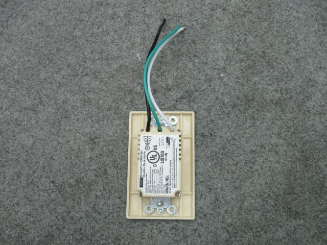
QIE0738-02
Jan 20, 2010Wireless Duplex Receptacle
Equipment Class
DXX - Part 15 Low Power Communication Device Transmitter