QIE0763-03Wireless Switch
Advanced Control Technologies, Inc.
Click to zoom
Application Details
- Equipment Class
- DXX - Part 15 Low Power Communication Device Transmitter
- Date of Grant
- Jan 12, 2010
- Application Purpose
- Original Equipment
- Date of Application
- Jan 11, 2010
- Equipment Note
- Wireless Switch
- Frequency Range
- 908.40000000 - 908.40000000
- Country
- United States
Documents & Files
Document Text
Text extracted from the exhibit documents filed with the FCC. Open a document above to read the original.
Users Manual
Z-Wave ZRW103 Series 300 Instructions, Release 3.1 P/D 010510 HomePro by ADVANCED CONTROL TECHNOLOGIES, INC. 0763-03 1 Z-Wave Radio Frequency (RF) Controlled, 120 VAC, Wall Mounted Switch, 3-Way, Series 300, Release 3.1 ZRW103 HomePro RF Home Automation ZRW103 WALL MOUNTED SWITCH The ZRW103 Wall Mounted 3-Way Switch is a component of the HomePro lighting control system. Wire the Wall Mounted Switch in place of the standard wall switch according to the diagram above and program from the Wireless Controller to operate loads. Inclusion of this Switch on the ZTH100 Wireless Controller menu allows remote ON/OFF control of lamps connected. This Wall Mounted Switch is designed to work with other Z-Wave enabled devices. Z-Wave nodes of other types can be added to the system and will also act as repeaters if they support this function of repeating the signal received to other modules in the system. As part of a Z-Wave network, the ZRW103 will also act as a wireless repeater to insure that commands intended for another device in the network are received. This is useful when the device would otherwise be out of the radio range of the wireless controller. There are no field repairable assemblies on this unit.. If service is needed, the unit must be returned where purchased. DANGER! SHOCK HAZARD. Read and understand these instructions before installing. This device is intended for installation in accordance with the National Electric code and local regulations in the United States, or the Canadian Electrical Code and local regulations in Canada. It is recommended that a qualified electrician perform this installation. Make sure the load controlled by the switch does not exceed 2400 watts. For indoor use only. Retain instructions for future use. INSTALLATION Wire this Switch in place of a current wall switch according to the diagram above. When used, AS101’s are required to be wired to the same line (or neutral) which is also wired to the master unit as well as the load being controlled, and not wired to any other neutral. If multiple neutrals are tied together in one box, separate the neutrals to preserve the integrity of the ZRW103 circuit. Caution! Do not wire unit “live” (with power on the circuit) and do not allow the yellow wire to contact line voltage, neutral or ground or you will damage the device. Refer to your Controller operating instructions to add this module under the command of the Wireless Controller. Shown with supplied Decora TM trim plate Note: This module must be “Included in the Network” only where it will be permanently installed. The proper opera- tion of this node in the mesh network is dependent on it knowing its location with respect to other nodes. You cannot “test bench” configure this module, then install. • This product supports Zensor Net Beam technology. Z-Wave ZRW103 Series 300 Instructions, Release 3.1 P/D 010510 HomePro by ADVANCED CONTROL TECHNOLOGIES, INC. 0763-03 2 INCLUDING ZRW103 TO THE NETWORK STEP 1. Prepare the Controller to include a unit to the network by adding it to a group (method of adding a node to the network). Refer to controller instructions. STEP 2. The ZRW103 must be in its permanently installed location. Tap either the top or bottom of the ZRW103 once. STEP 3. You should see an indication on your Controller that the “DEVICE WAS INCLUDED” in the network. NOTE: If you have trouble adding the ZRW103 to a group it may be that the Home ID and Node ID were not cleared from it after testing. You must first “RESET UNIT” with your controller to remove it from the network. If using the ZTH100, select “SETUP” and scroll to “RESET UNIT” Although adding it to a group includes it in the network, removing it from a group does not remove it from the network. If removed from a group, it functions as a repeater (only). “RESET UNIT” removes it completely from the network. BASIC OPERATION (Local Control) The switch paddle on the ZRW103 allows the user to: • Turn the attached load on or off. • Include or exclude the module from the Z-Wave system • Control other Z-Wave enabled devices. Also, when a controller prompts you to “Send Node ID” or to “Press Button on Unit”, quickly tap the switch on or off once to satisfy those instructions. • Tapping top of switch turns the load attached ON. • Tapping bottom of switch turns the load attached OFF. • Pressing and holding switch does not effect the load attached to the ZRW103, but will allow dimming and brightening of Z-Wave dimmers if associated (see below for details). LED indication The LED on the ZRW103 will turn on when the load attached is ON. The LED can be user configured however to turn ON when the load attached is OFF, if so desired, to act as a night light. See ADVANCED OPERATION section. The ZRW103 will flicker its LED when it is transmitting to any of its 2 groups. This can be changed if desired. See ADVANCED OPERATION section. Auxiliary Switch The ZRW103 supports the AS101 auxiliary switch to provide 3-way or 4-way operation. Remote Control The ZRW103 will respond to BASIC and BINARY commands that are part of the Z-Wave system. Refer to your controller’s instructions as to whether your controller can transmit those commands. Internal circuit protection The ZRW103 internal circuitry is protected by an internal fuse. This internal fuse is factory serviceable only. Check your home circuit breakers before concluding that the product must be returned to manufacturer for repair at a nominal charge. ADVANCED OPERATION All On/All Off The ZRW103 supports the ALL ON/ ALL OFF commands. The ZRW103 can be set to respond to ALL ON and ALL OFF commands four different ways. Refer to your controller for information on how to set the ZRW103 to operate in the manner you desire. Some controllers may be only able to set certain settings of ALL ON/ALL OFF response. Z-Wave ZRW103 Series 300 Instructions, Release 3.1 P/D 010510 HomePro by ADVANCED CONTROL TECHNOLOGIES, INC. 0763-03 3 The four different ways the ZRW103 can be setup to …
Text truncated - open the document above for the full version.
Users Manual
LSM-20 Instructions P/D 112609 LSM-20 by EVOLVE GUEST CONTROLS 1 Evolve Radio Frequency (RF) Controlled, 120 VAC, Wall Mounted Switch, 3-Way, Release 3.1 LSM-20 LSM-20 WaLL Mounted SWitch The LSM-20 Wall Mounted 3-Way Switch is a component of the Evolve lighting control system. Wire the Wall Mounted Switch in place of the standard wall switch according to the diagram above and program from the Wireless Controller to operate loads. Inclusion of this Switch on the IR-100 Wireless Controller menu allows remote ON/OFF control of lamps connected. This Wall Mounted Switch is designed to work with other Evolve enabled devices. Evolve nodes of other types can be added to the system and will also act as repeaters if they support this function of repeating the signal received to other modules in the system. As part of a Evolve network, the LSM-20 will also act as a wireless repeater to insure that commands intended for another device in the network are received. This is useful when the device would otherwise be out of the radio range of the wireless controller. There are no field repairable assemblies on this unit.. If service is needed, the unit must be returned where purchased. danGeR! Shock hazaRd. Read and understand these instructions before installing. This device is intended for installation in accor- dance with the National Electric code and local regulations in the United States, or the Canadian Electrical Code and local regulations in Canada. It is recommended that a qualified electrician perform this installation. Make sure the load controlled by the switch does not exceed 2400 watts. For indoor use only. Retain instructions for future use. inStaLLation Wire this Switch in place of a current wall switch according to the diagram above. When used, AS101’s are required to be wired to the same line (or neutral) which is also wired to the master unit as well as the load being controlled, and not wired to any other neutral. If multiple neutrals are tied together in one box, separate the neutrals to preserve the integrity of the LSM-20 circuit. caution! Do not wire unit “live” (with power on the circuit) and do not allow the yellow wire to contact line voltage, neutral or ground or you will damage the device. Refer to your Controller operating instructions to add this module under the command of the Wireless Controller. incLudinG LSM-20 to the netWoRk SteP 1. Prepare the Controller to include a unit to the network by adding it to a group (method of adding a node to the network). Refer to controller instructions. Shown with supplied Decora TM trim plate note: This module must be “Included in the Network” only where it will be permanently installed. The proper operation of this node in the mesh network is dependent on it knowing its location with respect to other nodes. You cannot “test bench” configure this module, then install. LSM-20 Instructions P/D 112609 LSM-20 by EVOLVE GUEST CONTROLS 2 The LSM-20 supports the Association command. The LSM-20 can be set to control other Evolve devices. You can turn on and off, and even dim other Evolve devices once they are “associ- ated” into either of 2 groups with the LSM-20. A NOTE AbOUT DIMMERS IN A GROUP: If you combine Evolve enabled dimmers and other types of Evolve devices in a group, place a Evolve enabled dimmer into the empty group first to ensure that the dimming operates correctly. Each group is turned on or off (or dimmed by tapping or holding) the switch a differing amount of times. If you associate a Evolve device into Group 2, you can turn that device on and off by tapping the switch on or off twice. You can brighten or dim devices by tapping the switch on or off once and then holding the switch down. The load attached to the LSM-20 is not affected. If you associate a Evolve device into Group 3, you can turn that device on and off by tapping the switch on or off three times. You can brighten or dim devices by tapping the switch on or off twice and then hold the top or bottom of the switch down. The load attached to the LSM-20 is not affected. You can associate up to 5 Evolve devices into each of these groups. For instructions on how to associate a Evolve device into one of these groups, refer to your wireless controller instructions. (If you are using the IR-100 controller, refer to the Setup Menu, Association section). Configuration The LSM-20 supports the Configuration command. The LSM-20 can be configured to operate slightly differently than how it works when you first install it. Using the Configuration command you can configure the following: You can use a IR-100 to send Configuration commands. (Refer to the Setup Menu, Configuration section) Set ignore Start Level Bit When transmitting dim commands The LSM-20 can send Dim commands to Evolve enabled dimmers. The Dim command has a start level embedded in it. A dimmer receiv- ing this command will start dimming from that start level if this bit is set to 0. If the bit is set to 1, the dimmer will ignore the start level and instead start dimming from its current level. • Parameter No: 1 • Length: 1 Byte • Valid Values = 0 or 1 (default 1) night Light The LED on the LSM-20 will by default, turn ON when the load attached is turned ON. To make the LED turn ON when the load attached is turned OFF instead, set parameter 3 to a value of 1. • Parameter No: 3 • Length: 1 Byte • Valid Values = 0 or 1 (default 0) invert Switch To change the top of the switch to OFF and the bottom of the switch ON , set parameter 4 to 1. • Parameter No: 4 • Length: 1 Byte • Valid Values = 0 or 1 (default 0) enable Shade control Group 2 The LSM-20 can control shade control devices via its group 2 if this configuration parameter is set to 1. • Parameter 14 • Length: 1 Byte • Valid Values: 0 or 1 (default 0) Enable Shade Control Group 3 The LSM-20 can control shade control devices via its group 3 if this configuration parameter is set to 1. LSM-20 Instructions P/D 112609 LSM-20 by EVOLVE GUEST CONTROLS 3 SteP 2. the …
Text truncated - open the document above for the full version.
ID Label/Location Info
HomePro TM RF Wall SwitchModel ZRW103A Resistive Load...20A , 120 Volts AC, 60 Hz, Series 200, Rel 2.2 Incandescent Load...960W Motor Load...1 HP 908.42 MHz S/N: FCC ID: QIE0763-0X Canada IC: 4436A-07630X WARNING: Do not exceed electrical ratings. ZRW103A (Almond) Series 200 Product Label Artwork Affix to side of product Radius corners of label 1/8” (or .125”) “WARNING” is on label P/D 043008 PRODUCT LABEL To be made from 80Y (UL file PGDQ2.MH13653) or equvalent. Must comply with UL969. 2.000” 1.000” Date Code: 3B54A Maximum 5/8” wide. Center on end of product Advanced Control Technologies, Inc., Indianapolis, IN Made in China BLK-Line WHI-Neutral. BLU-Load GRN-Grnd YEL-AS101 HomePro TM RF Wall SwitchModel ZRW103I Resistive Load...20A , 120 Volts AC, 60 Hz, Series 200, Rel 2.2 Incandescent Load...960W Motor Load...1 HP 908.42 MHz S/N: FCC ID: QIE0763-0X Canada IC: 4436A-07630X WARNING: Do not exceed electrical ratings. ZRW103I (Ivory) Series 200 Product Label Artwork Affix to side of product Radius corners of label 1/8” (or .125”) “WARNING” is on label P/D 043008 PRODUCT LABEL To be made from 80Y (UL file PGDQ2.MH13653) or equvalent. Must comply with UL969. 2.000” 1.000” Date Code: 3B54A Maximum 5/8” wide. Center on end of product Advanced Control Technologies, Inc., Indianapolis, IN Made in China BLK-Line WHI-Neutral. BLU-Load GRN-Grnd YEL-AS101 HomePro TM RF Wall SwitchModel ZRW103W Resistive Load...20A , 120 Volts AC, 60 Hz, Series 200, Rel 2.2 Incandescent Load...960W Motor Load...1 HP 908.42 MHz S/N: FCC ID: QIE0763-0X Canada IC: 4436A-07630X WARNING: Do not exceed electrical ratings. ZRW103W (White) Series 200 Product Label Artwork Affix to side of product Radius corners of label 1/8” (or .125”) “WARNING” is on label P/D 043008 PRODUCT LABEL To be made from 80Y (UL file PGDQ2.MH13653) or equvalent. Must comply with UL969. 2.000” 1.000” Date Code: 3B54A Maximum 5/8” wide. Center on end of product Advanced Control Technologies, Inc., Indianapolis, IN Made in China BLK-Line WHI-Neutral. BLU-Load GRN-Grnd YEL-AS101
Test Report
BUREAU VERITAS TESTREPORTN°:(5210)004-0127 TESTREPORT To: ADVANCEDCONTROL TECHNOLOGIES,INC. To: Attn: KevinShelowAttn: Address:8076WoodlandDrive,Indianapolis,IN 46278 Address: Fax:Fax: [email protected]:E-mail: MEW-09N0169ATHS-B FolderNo.: Location: FCCID: Factoryname: MEGAWORLDHOLDINGSLTD. UnitJ, 13/F.,WorldTechCentre,95HowMingStreet,KwunTong,HongKong Product: RFWallMount3-WaySwitch ModelNo.:ZRW103W AdditionalModel:ZRW103AIZRW10311LSM20WILSM20AILSM201 SampleNo: (5209)323-0762 Testdate: TestRequested: November25,2009 FCCPart15- 2008 TestMethod: ANSIC63.4- 2003 QIE0763-03 Theresultsgivenin thisreportarerelatedto thetestedspecimenof thedescribedelectricalapparatus. AuthorizedSignature: CONCLUSION:ThesubmittedsamplewasfoundtoCOMPLYwithrequirementof FCCPart15SubpartC. Date:January7,2010 Reviewedby:KeithYeunq Aooroved/bv:StevenTsanq Date:January7, 2010 BUREAUVERITASHONGKONGLlMITED- KowloonBayOffice 1/FPacificTradeCentre, 2 KaiHingRoad,KowloonBay, Kowloon,HONGKONG Tel:+85223310888 Fax:+85223310889 www.cps.bureauveritas.com ThisreportISIntendedforyourexclusiveuse.Anycopyingorreplicationofthisreporttoorforanyotherpersonorentity,oruse ofournameortrademark,ispermittedonlywithourpriorwrittenpermission.Ourreportislimitedtothetestsamplesidentified herein.Theresultssetforthinthisreportarenotnecessarilyindicativeorrepresentativeofthestatisticalqualityorcharacteristicsof thelotfromwhicha testsamplewastakenoranysimilaroridenticalproductunlessspecificallyandexpresslynoted.Ourreport includesallofthetestsrequestedbyyouandtheresultsthereofYoushallhavethirtydaysfromreceiptofthisreporttorequest additionaltestingofthesamplesortonotifyusofanyerrorsoromissionsrelatingtoourreport,provided,however,suchnotice shallbeinwritingandshallspecificallyaddresstheissueyouwishtoraise.Afailuretoraisesuchissuewithintheprescribedtime shallconstituteyourunqualifiedacceptanceofthecompletenessofthisreport,thetestsconductedandthecorrectnessofthereport contents. Page1of 20 TEST REPORT N°: (5210)004-0127 BUREAU VERITAS HONG KONG LIMITED – Kowloon Bay Office 1/F Pacific Trade Centre, 2 Kai Hing Road, Kowloon Bay, Kowloon,HONG KONG Tel: +852 2331 0888 Fax: +852 2331 0889 www.cps.bureauveritas.com This report is intended for your exclusive use. Any copying or replication of this report to or for any other person or entity, or use of our name or trademark, is permitted only with our prior written permission. Our report is limited to the test samples identified herein. The results set forth in this report are not necessarily indicative or representative of the statistical quality or characteristics of the lot from which a test sample was taken or any similar or identical product unless specifically and expressly noted. Our report includes all of the tests requested by you and the results thereof. You shall have thirty days from receipt of this report to request additional testing of the samples or to notify us of any errors or omissions relating to our report, provided, however, such notice shall be in writing and shall specifically address the issue you wish to raise. A failure to raise such issue within the prescribed time shall constitute your unqualified acceptance of the completeness of this report, the tests conducted and the correctness of the report contents. Page 2 of 20 Location of the test site Radiated and Conducted emissions measurements are investigated and taken pursuant to the procedures of ANSI C63.4 – 2003. An Open Area Test Site and Full Anechoic Chamber (FCC Listed Site, Registration No. 642151) are set up for investigation and located at : BUREAU VERITAS HONG KONG LIMITED, EMC CENTRE No. 2106-2107, 21/F., Westin Centre, 26 Hung To Road, Kwun Tong, Kowloon, Hong Kong List of measuring equipment Radiated Emission EQUIPMENT MANUFACTURER MODEL NO. SERIAL NO. CALIBRATION DUE EMI TEST RECEIVER R&S ESCI 100379 24-AUG-2010 BILOG ANTENNA SCHAFFNER CBL6112D 25229 31-MAY-2010 OPEN AREA TEST SITE BVCPS N/A N/A 03-JULY-2010 ANECHOIC CHAMBER ALBATROSS M-CDC 80374004499B 07-JULY-2010 HORN ANTENNA SCHWARZBECK BBHA9120D 9120D-692 21-JULY-2010 PREAMPLIFIER SCHWARZBECK BBV9718 9718-152 27-JULY-2010 COAXIAL CABLE SUHNER N/A N/A 11-MAY-2010 SPECTRUM ANALYZER ADVANTEST R3127 111000909 02-DEC-2009 Conducted Emission EQUIPMENT MANUFACTURER MODEL NO. SERIAL NO. CALIBRATION DUE EMI TEST RECEIVER R&S ESCS30 830986/030 26-SEP-2010 LISN R&S ENV216 100024 25-MAR-2010 Remarks:- N/A : Not Applicable or Not Available The measurement instrumentation uncertainty would be taking into consideration on each of the test result TEST REPORT N°: (5210)004-0127 BUREAU VERITAS HONG KONG LIMITED – Kowloon Bay Office 1/F Pacific Trade Centre, 2 Kai Hing Road, Kowloon Bay, Kowloon,HONG KONG Tel: +852 2331 0888 Fax: +852 2331 0889 www.cps.bureauveritas.com This report is intended for your exclusive use. Any copying or replication of this report to or for any other person or entity, or use of our name or trademark, is permitted only with our prior written permission. Our report is limited to the test samples identified herein. The results set forth in this report are not necessarily indicative or representative of the statistical quality or characteristics of the lot from which a test sample was taken or any similar or identical product unless specifically and expressly noted. Our report includes all of the tests requested by you and the results thereof. You shall have thirty days from receipt of this report to request additional testing of the samples or to notify us of any errors or omissions relating to our report, provided, however, such notice shall be in writing and shall specifically address the issue you wish to raise. A failure to raise such issue within the prescribed time shall constitute your unqualified acceptance of the completeness of this report, the tests conducted and the correctness of the report contents. Page 3 of 20 Equipment Under Test [EUT] Description of Sample: Model Name: RF Wall Mount 3-Way Switch Model Number: ZRW103W / ZRW1…
Text truncated - open the document above for the full version.
Test Setup Photos
TEST REPORT N°: (5209)343-0595 BUREAU VERITAS HONG KONG LIMITED – Kowloon Bay Office 1/F Pacific Trade Centre, 2 Kai Hing Road, Kowloon Bay, Kowloon,HONG KONG Tel: +852 2331 0888 Fax: +852 2331 0889 www.cps.bureauveritas.com This report is intended for your exclusive use. Any copying or replication of this report to or for any other person or entity, or use of our name or trademark, is permitted only with our prior written permission. Our report is limited to the test samples identified herein. The results set forth in this report are not necessarily indicative or representative of the statistical quality or characteristics of the lot from which a test sample was taken or any similar or identical product unless specifically and expressly noted. Our report includes all of the tests requested by you and the results thereof. You shall have thirty days from receipt of this report to request additional testing of the samples or to notify us of any errors or omissions relating to our report, provided, however, such notice shall be in writing and shall specifically address the issue you wish to raise. A failure to raise such issue within the prescribed time shall constitute your unqualified acceptance of the completeness of this report, the tests conducted and the correctness of the report contents. Page 23 of 23 Measurement of Conducted Emission Test Set Up Measurement of Radiated Emission Test Set Up ***** End of Report *****
Contact Information
Applicant
Josh Hansen(Regulatory Engineer)
Test Firm
Bureau Veritas Hong Kong LimitedSteven Tsang
[email protected]85223310728
Technical Specifications
| # | Rule Parts | Frequency Range | Power Output |
|---|---|---|---|
| 1 | 15C | 908.4 MHz - 908.4 MHz | - |
Other Applications from Advanced Control Technologies, Inc.

QIE0810-01
Oct 20, 2011Dimmer
Equipment Class
DXT - Part 15 Low Power Transceiver, Rx Verified
QIE0791-01
Oct 27, 2010Wireless Switch
Equipment Class
DXT - Part 15 Low Power Transceiver, Rx Verified
QIE0792-01
Aug 24, 2010Wall Mounted Dimmer
Equipment Class
DXT - Part 15 Low Power Transceiver, Rx Verified
QIE0797-01
Jul 21, 2010Wall Mounted Dimmer
Equipment Class
DXT - Part 15 Low Power Transceiver, Rx Verified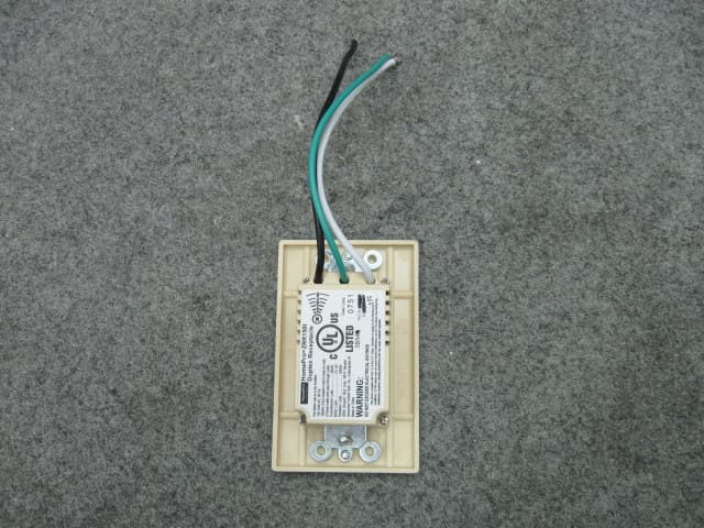
QIE0738-02
Jan 20, 2010Wireless Duplex Receptacle
Equipment Class
DXX - Part 15 Low Power Communication Device Transmitter